HCD-VZ50MD
E Model
Tourist Model
SERVICE MANUAL
MINI Hi-Fi COMPONENT SYSTEM
-- Continued on next page --
SPECIFICATIONS
HCD-VZ50MD is the tuner, deck, CD, MD and
amplifier section in DHC-VZ50MD.
This stereo system is equipped with the Dolby B-type
noise reduction system*.
* Manufactured under license from Dolby
Laboratories Licensing Corporation.
DOLBY and the double-D symbol ; are
trademarks of Dolby Laboratories Licensing
Corporation.
Model Name Using Similar Mechanism
NEW
CD Mechanism Type
CDM53F-K4BD37
Base Unit Type
BU-K4BD37
Optical Pick-up Type
KSM-213DHAP/Z-NP
Model Name Using Similar Mechanism
HCD-ZX50MD
MD Mechanism Type
MDM-7B
Optical Pick-up Type
KMS-260B/J1N
Model Name Using Similar Mechanism
HCD-ZX50MD
Tape Transport Mechanism Type
TCM-230AWR12
CD
SECTION
MD
SECTION
TAPE DECK
SECTION
Amplifier section
The following measured at 120/220/240 V AC, 50/60 Hz
DIN power output (rated) 115 + 115 watts
(6 ohms at 1 kHz, DIN)
Continuous RMS power output (reference)
150 + 150 watts
(6 ohms at 1 kHz,
10 % THD)
Inputs
VIDEO (AUDIO) IN:
voltage 250 mV,
(phono jacks)
impedance 47 kilohms
MIC 1/2:
sensitivity 1 mV,
(mini jack)
impedance 10 kilohms
Outputs
VIDEO OUT:
max. output level
(phono jack)
1 Vp-p, unbalanced,
Sync negative, load impedance
75 ohms
S-VIDEO OUT:
Y: 1 Vp-p, unbalanced,
(4-pin/mini-DIN jack)
Sync negative,
C: 0.286 Vp-p,
load impedance 75 ohms
PHONES:
accepts headphones of
(stereo mini jack)
8 ohms or more
FRONT SPEAKER:
accepts impedance of 6 to 16 ohms
SUPER WOOFER:
Voltage 1 V, impedance 1 kilohms
VIDEO CD/CD player section
System
Compact disc and digital audio
system
Laser
Semiconductor laser
(
=780 nm)
Emission duration: continuous
Laser output
Max. 44.6
µW*
*This output is the value measured
at a distance of 200 mm from the
objective lens surface on the
Optical Pick-up Block with 7 mm
aperture.
Wavelength
780 790 nm
Frequency response
2 Hz 20 kHz (
±0.5 dB)
Signal-to-noise ratio
More than 90 dB
Dynamic range
More than 90 dB
Video color system format
NTSC, PAL
MD deck section
System
MiniDisc digital audio system
Laser
Semiconductor laser (
=780 nm)
Emission duration: continuous
Laser output
Max. 44.6
µW*
*This output is the value measured
at a distance of 200 mm from the
objective lens surface on the
Optical Pick-up Block with a
7 mm aperture.
Sampling frequency
44.1 kHz
Frequency response
20 20,000 Hz
Tape player section
Recording system
4-track 2-channel stereo
Frequency response
40 13,000 Hz (
±3 dB),
(DOLBY NR OFF)
using Sony TYPE I cassette
40 14,000 Hz (
±3 dB),
using Sony TYPE II cassette
Ver 1.1 2002. 06
Sony Corporation
Home Audio Company
Published by Sony Engineering Corporation
9-929-529-12
2002F1600-1
© 2002.06

file:///C|/Documents%20and%20Settings/bob/My%20Documents/manualdirectory.htm
This file was downloaded and provided FREE OF CHARGE
from the ManualDirectory community.
You can find many free to download Service Manuals & Schematics at
http://www.manualdirectory.co.uk
file:///C|/Documents%20and%20Settings/bob/My%20Documents/manualdirectory.htm01/04/2007 01:34:00
2
Procedure for using the Self-Diagnosis Function (Error History Display Mode).
Note: Perform the self-diagnosis function in the "error history display mode" in the test mode. The following describes the least required
procedure. Be careful not to enter other modes by mistake. If other modes are entered accidentally, press the NAME EDIT/
CHARACTER button while REC IT is lit, and when REC IT goes off, press the MD Z button to exit the mode.
1.
In the power ON state, set the function to MD, and while pressing the DISPLAY and x buttons together, press V-GROOVE . While
the test mode is set. "[Check]" will be displayed.
2.
Move the multi-stick left and right to display "[Service]" and press the PUSH ENTER button.
3.
Move the multi-stick left and right to display "Err Display".
4.
Press the PUSH ENTER button to enter the error history mode. "op rec tm" will be displayed.
5.
Select the item to be displayed or executed using the multi-stick.
6.
Press the NAME EDIT/CHARACTER button so that REC IT lights up.
7.
Press the MD REC MODE button to display the selected item.
8.
Press the REC MODE button another time to return to step 4.
9.
Pressing the CLEAR button when REC IT is lit displays "Err Display" and exits the error history display mode.
10. To exit the test mode, press the MD Z button while REC IT is off. This sets the standby state and ends the test mode.
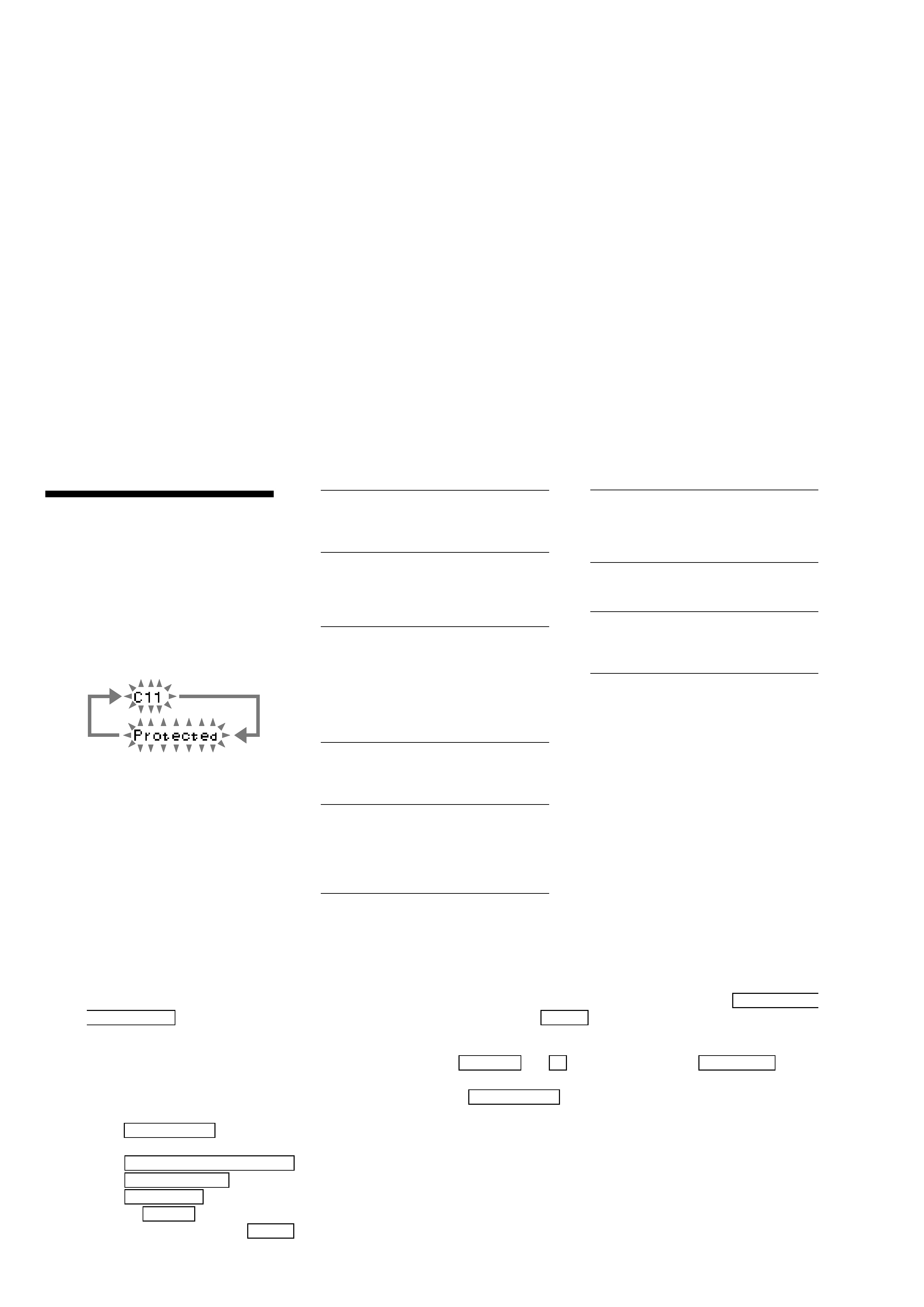
Self-diagnosis Display
This system has the Self-diagnosis display
function to let you know if there is a system
malfunction. The display shows a code made up of
three or five letters and a message alternately to
show you the problem. To solve the problem, refer
to the following list. If any problem persists,
consult your nearest Sony dealer.
C11 / Protected
The MD is protected against erasure.
p Remove the MD and slide the tab to close the
slot (page 49).
C12 / Cannot Copy
You are attempting to record a CD with a
format that the system does not support, such as
CD-ROM.
p
C13 / REC Error
Recording is not possible.
p Move the system to a stable place and start
recording over from the beginning.
The MD is dirty or is scratched or the MD does
not meet the standards.
p Change the MD with another one and start
recording over from the beginning.
C13 / Read Error
The MD cannot read the disc information
correctly.
p Eject the MD once, then insert it again.
C14 / Toc Error
The MD cannot read the disc information
correctly.
p Change the MD with another one.
p Erase all the recorded contents of the MD
using the Erase function.
C41 / Cannot Copy
This unit complies with the Serial Copy
Management System (SCMS) which limits the
number of digital copies that can be made of
any given digital audio source.
E0001 / MEMORY NG
The component has internal problems.
p Consult your nearest Sony dealer.
E0101 / LASER NG
There is a problem with the laser pickup.
p The laser pickup may be damaged. Consult
your nearest Sony dealer.
Tuner section
FM stereo, FM/AM superheterodyne tuner
FM tuner section
Tuning range
Tourist model:
76.0 108.0 MHz
Other models:
87.5 108.0 MHz
Antenna
FM lead antenna
Antenna terminals
75 ohm unbalanced
Intermediate frequency
10.7 MHz
AM tuner section
Tuning range
531 1,602 kHz
(with the interval set at
9 kHz)
530 1,710 kHz
(with the interval set at
10 kHz)
Antenna
AM loop antenna
Antenna terminals
External antenna terminal
Intermediate frequency
450 kHz
General
Power requirements
120 V, 220 V, 230 240 V AC,
50/60 Hz
Adjustable with voltage selector
Power consumption
180 watts
Dimensions (w/h/d)
Approx. 250 x 375 x 395 mm
Mass
Approx. 12.0 kg
Supplied accessories:
AM loop antenna (1)
FM lead antenna (1)
Remote Commander (1)
Batteries (2)
Video cable (1)
Speaker cords (2)
Front speaker pads (8)
Design and specifications are subject to change
without notice.
3
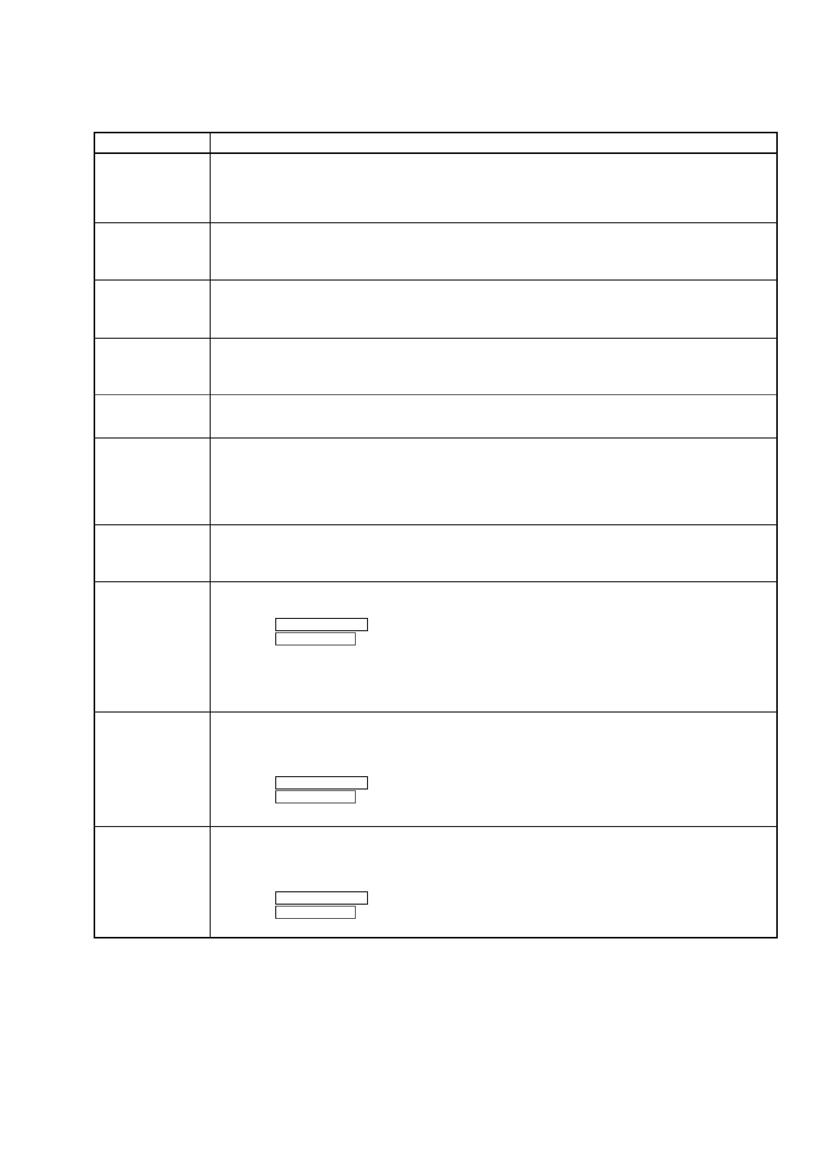
ITEMS OF ERROR HISTORY MODE ITEMS AND CONTENTS
Selecting the Test Mode
Display
op rec tm
op play tm
spdl rp tm
retry err
total err
err history
retry adrs
er refresh
op change
spdl change
History
Displays the total recording time.
When the total recording time is more than 1 minute, displays the hour and minute
When less than 1 minute, displays "Under 1 min"
The display time is the time the laser is set to high power, which is about 1/4 of the actual recording time.
Displays the total playback time.
When the total playback time is more than 1 minute, displays the hour and minute
When less than 1 minute, displays "Under 1 min"
Displays the total rotating time of the spindle motor.
When the total rotating time is more than 1 minute, displays the hour and minute
When less than 1 minute, displays "Under 1 min"
Displays the total number of retry errors during recording and playback
Displays "r xx p yy". xx is the number of errors during recording. yy is the number of errors during playback.
This is displayed in hexadecimal from 00 to FF.
Displays the total number of errors
Displays "total xx". This is displayed in hexadecimal from 00 to FF.
Displays the past ten errors.
Displays "0x ErrCd@@".
X is the history number. The younger the number, the more recent is the history (00 is the latest). @@ is the
error code.
Select the error history number using the Multi stick.
Displays the past five retry addresses.
Displays "xx ADRS yyyy", xx is the history number, yyyy is the cluster with the retry error.
Select the error history number using the Multi stick.
Mode for erasing the error and retry address histories
Procedure
1. Press the MD REC MODE button while "REC IT" is lit when displayed as "er refresh".
2. Press the PUSH ENTER button when the display changes to "er refresh?".
When "Complete!!" is displayed, it means erasure has completed.
Be sure to check the following after executing this mode.
*Data has been erased.
*Perform recording and playback, and check that the mechanism is normal.
Mode for erasing the total time of op rec tm, op play tm.
These histories are based on the time of replacement of the optical pick-up. If the optical pick-up has been
replaced, perform this procedure and erase the history.
Procedure
1. Press the MD REC MODE button while "REC IT" is lit when displayed as "op change".
2. Press the PUSH ENTER button when the display changes to "op change?".
When "Complete!!" is displayed, it means erasure has completed.
Mode for erasing the total spdl rp tm time
These histories are based on the time of replacement of the spindle motor. If the spindle motor has been
replaced, perform this procedure and erase the history.
Procedure
1. Press the MD REC MODE button while "REC IT" is lit when displayed as "spdl change"
2. Press the PUSH ENTER button when the display changes to "spdl change?"
When "Complete!!" is displayed, it means erasure has completed.
4
Description
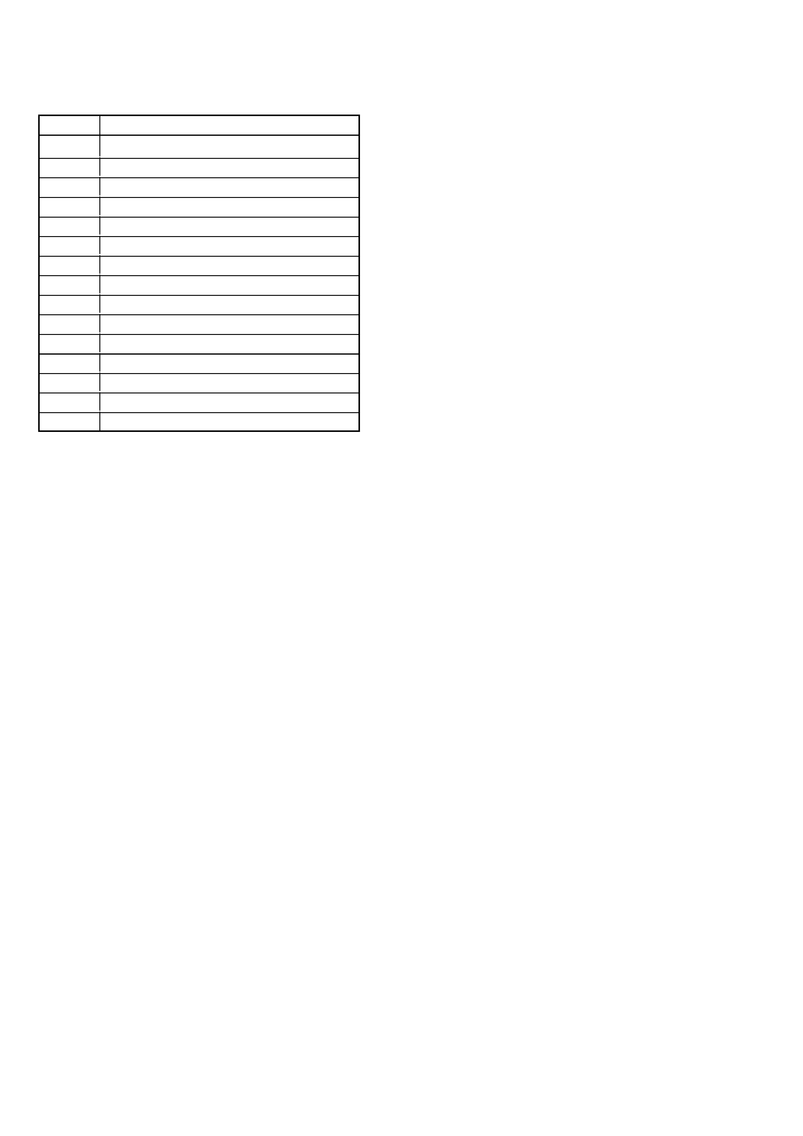
Table of Error Codes
Error Code
10
12
20
21
22
23
24
30
31
40
41
42
43
50
51
Could not load
Loading switches combined incorrectly
Timed out without reading the top of PTOC
Could read top of PTOC, but detected error
Timed out without accessing UTOC
Timed out without reading UTOC
Error in UTOC
Could not start playback
Error in sector
Retry cause generated during normal recording
Retried in DRAM overflow
Retry occurred during TOC writing
Retry aborted during S.F editing
Other than access processing, and could not read address.
Focus NG occurred and overran.