-- 1 --
SERVICE MANUAL
MICROFILM
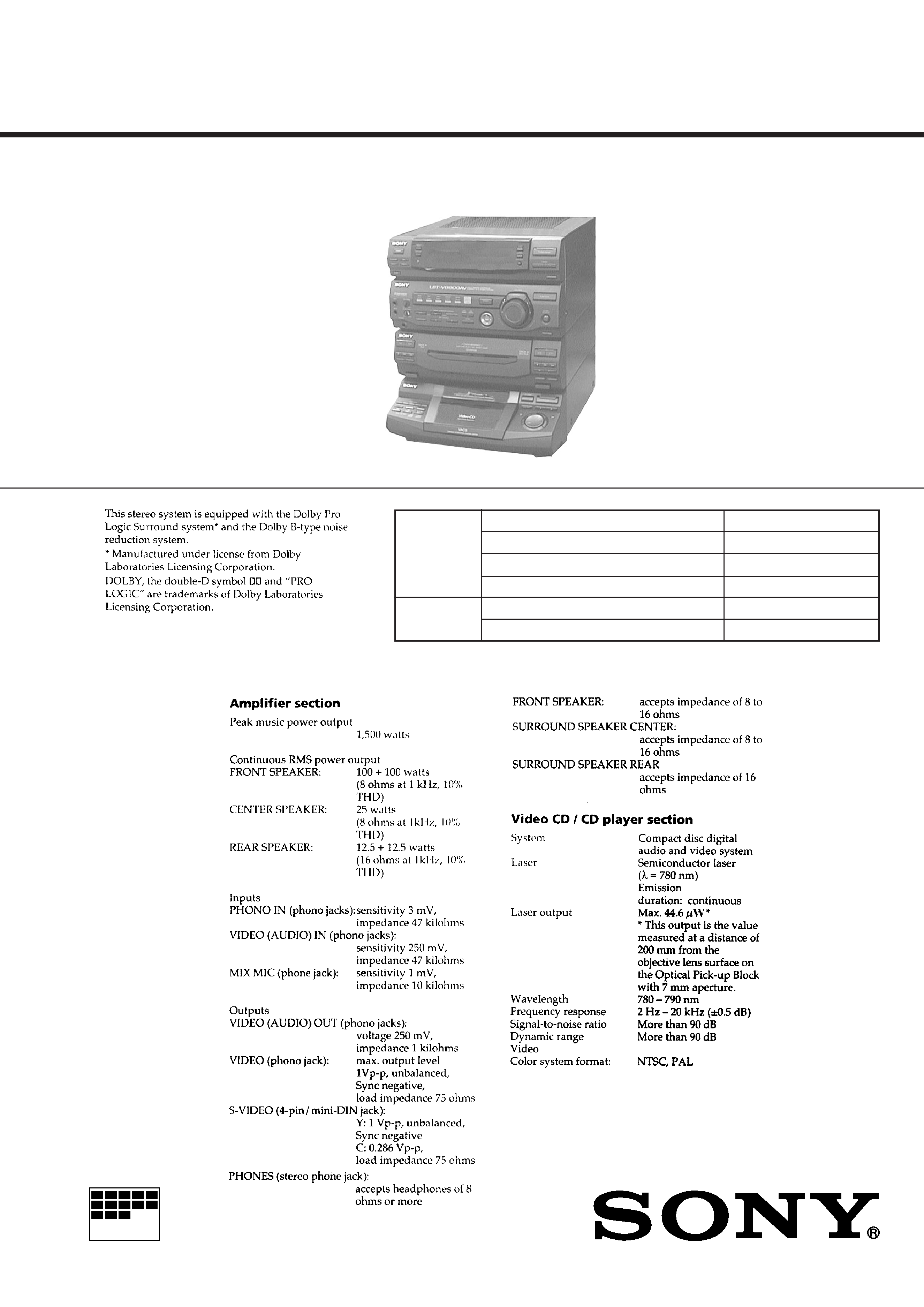
HCD-V8800 is the tuner, deck, Video CD and
amplifier section in LBT-V8800AV.
Model Name Using Similar Mechanism
HCD-V4500
CD Mechanism Type
CDM37L-5BD21AL
Base Unit Type
BU-5BD21AL
Optical Pick-up Type
KSS-213D/Q-NP
Model Name Using Similar Mechanism
HCD-V4500
Tape Transport Mechanism Type
TCM-220WR2
CD
SECTION
SPECIFICATIONS
E Model
Chinese Model
-- Continued on next page --
TAPE
DECK
SECTION
HCD-V8800
COMPACT DISC DECK RECEIVER
-- 2 --
CAUTION
Use of controls or adjustments or performance of procedures
other than those specified herein may result in hazardous ra-
diation exposure.
Notes on chip component replacement
· Never reuse a disconnected chip component.
· Notice that the minus side of a tantalum capacitor may be
damaged by heat.
Flexible Circuit Board Repairing
· Keep the temperature of soldering iron around 270°C
during repairing.
· Do not touch the soldering iron on the same conductor of the
circuit board (within 3 times).
· Be careful not to apply force on the conductor when soldering
or unsoldering.
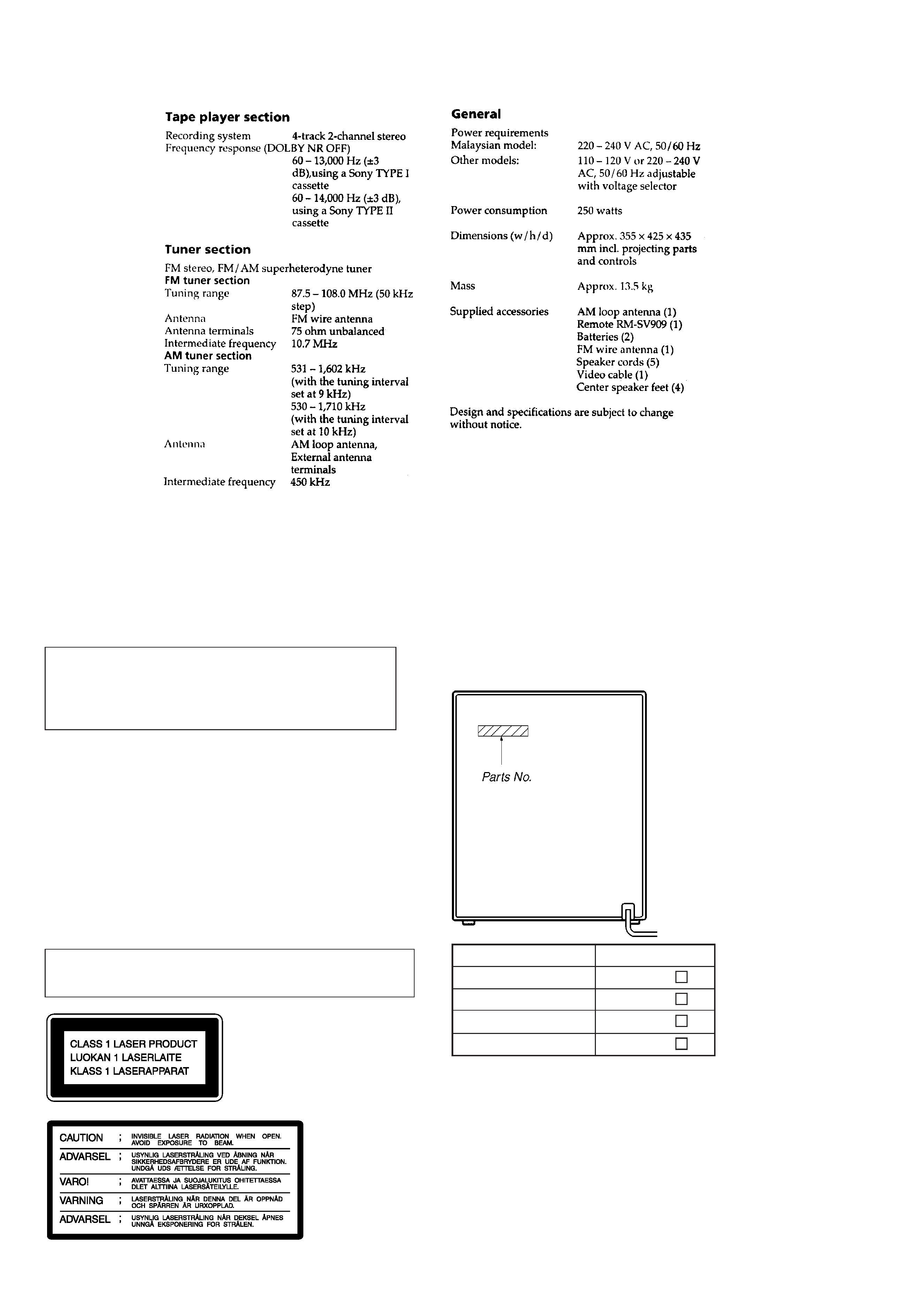
Laser component in this product is capable of emitting radiation
exceeding the limit for Class 1.
This appliance is classified as
a CLASS 1 LASER product.
The CLASS 1 LASER PROD-
UCT MARKING is located on
the rear exterior.
This caution
label is located
inside the unit.
MODEL IDENTIFICATION
-- BACK PANEL --
E, SP model
MY model
CH model
IA model
MODEL
PARTS No.
4-992-220-0
4-992-220-1
4-992-220-2
4-992-220-3
· Abbreviation
SP : Singapore model
MY : Malaysia model
IA : Indonesian model
CH : Chinese model
SAFETY-RELATED COMPONENT WARNING !!
COMPONENTS IDENTIFIED BY MARK
! OR DOTTED LINE
WITH MARK
! ON THE SCHEMATIC DIAGRAMS AND IN
THE PARTS LIST ARE CRITICAL TO SAFE OPERATION.
REPLACE THESE COMPONENTS WITH SONY PARTS
WHOSE PART NUMBERS APPEAR AS SHOWN IN THIS
MANUAL OR IN SUPPLEMENTS PUBLISHED BY SONY.

-- 3 --
TABLE OF CONTENTS
1. SERVICING NOTE .......................................................... 4
2. GENERAL .......................................................................... 6
3. DISASSEMBLY
3-1. Front Panel ........................................................................... 7
3-2. Main Board ........................................................................... 8
3-3. Tape Mechanism Deck .......................................................... 8
3-4. Cassette Lid Assembly .......................................................... 9
3-5. CD Lid Assembly .................................................................. 9
3-6. CD Mechanism Deck .......................................................... 10
3-7. Base Unit ........................................................................... 10
3-8. Disc Table ........................................................................... 10
4. TEST MODE .............................................................. 11
5. MECHANICAL ADJUSTMENTS ........................... 12
6. ELECTRICAL ADJUSTMENTS ............................... 12
7. DIAGRAMS
7-1. Circuit Boards Location ...................................................... 17
7-2. Block Diagrams
· KEY CON Section ........................................................... 18
· CD Section ....................................................................... 19
· Video Section ................................................................... 21
· Deck Section .................................................................... 23
· Main Section .................................................................... 25
· Power Section .................................................................. 27
7-3. Printed Wiring Board -- CD Section -- ............................. 29
7-4. Schematic Diagram -- CD Section -- ............................... 31
7-5. Schematic Diagram -- Video Section -- ........................... 33
7-6. Printed Wiring Board -- Video Section -- ......................... 37
7-7. Printed Wiring Board -- Main Section -- .......................... 40
7-8. Schematic Diagram -- Main Section -- ............................ 43
7-9. Schematic Diagram -- Deck Section -- ............................ 47
7-10. Printed Wiring Board -- Deck Section -- ....................... 51
7-11. Schematic Diagram -- Panel Section -- ......................... 54
7-12. Printed Wiring Board -- Panel Section -- ....................... 57
7-13. Schematic Diagram -- Power Section -- ........................ 61
7-14. Printed Wiring Board -- Power Section -- ..................... 65
7-15. Schematic Diagram -- CD Motor Section -- .................. 68
7-16. Printed Wiring Board -- CD Motor Section -- ............... 69
7-17. Schematic Diagram -- KEY CON Section -- ................. 71
7-18. Printed Wiring Board -- KEY CON Section -- .............. 72
7-19. IC Block Diagrams ........................................................... 73
7-20. IC Pin Functions ............................................................... 80
8. EXPLODED VIEWS
8-1. Case and Back Panel Section .............................................. 97
8-2. Front Panel Section 1 .......................................................... 98
8-3. Front Panel Section 2 .......................................................... 99
8-4. Chassis Section ................................................................. 100
8-5. TC Mechanism Section-1 (TCM-220WR2) ..................... 101
8-6. TC Mechanism Section-2 (TCM-220WR2) ..................... 102
8-7. TC Mechanism Section-3 (TCM-220WR2) ..................... 103
8-8. CD Mechanism Section (CDM37L-5BD21AL) ............... 104
8-9. Base Unit Section (BU-5BD21AL) .................................. 105
9. ELECTRICAL PARTS LIST ...................................... 106
NOTES ON HANDLING THE OPTICAL PICK-UP BLOCK
OR BASE UNIT
The laser diode in the optical pick-up block may suffer electrostatic
break-down because of the potential difference generated by the
charged electrostatic load, etc. on clothing and the human body.
During repair, pay attention to electrostatic break-down and also
use the procedure in the printed matter which is included in the
repain parts.
The flexible board is easily damaged and should be handled with
care.
NOTES ON LASER DIODE EMISSION CHECK
The laser beam on this model is concentrated so as to be focused on
the disc reflective surface by the objective lens in the optical pick-
up block. Therefore, when checking the laser diode emission, ob-
serve from more than 30 cm away from the objective lens.
LASER DIODE AND FOCUS SEARCH OPERATION
CHECK
Carry out the "S curve check" in "CD section adjustment" and check
that the S curve waveform is output three times.

-- 4 --
SECTION 1
SERVICING NOTE
MC Cold Reset
· The cold reset clears all data including preset data stored in the
RAM to initial conditions. Execute this mode when returning the
set to the customer.
Procedure:
1. Press three buttons SPECTRUM ANALYZER , ENTER , and
DISC 1 simultaneously.
2. The fluorescent indicator tube becomes blank instantaneously,
and the set is reset.
CD Delivery Mode
· This mode moves the pick-up to the position durable to vibration.
Use this mode when returning the set to the customer after repair.
Procedure:
1. Press POWER button to turn the set ON.
2. Press PLAY MODE button and POWER button simultaneously.
3. A message "LOCK" is displayed on the fluorescent indicator
tube, and the CD delivery mode is set.
MC Hot Reset
· This mode resets the set with the preset data kept stored in the
memory. The hot reset mode functions same as if the power cord
is plugged in and out.
Procedure:
1. Press three buttons SPECTRUM ANALYZER , ENTER , and
DISC 2 simultaneously.
2. The fluorescent indicator tube becomes blank instantaneously,
and the set is reset.
Sled Servo Mode
· This mode can run the CD sled motor freely. Use this mode, for
instance, when cleaning the pick-up.
Procedure:
1. Select the function "CD".
2. Press three buttons SPECTRUM ANALYZER , ENTER , and
FUNCTION simultaneously.
3. The Sled Servo mode is selected, if "CD" is blanking on the
fluorescent indicator tube.
4. With the CD in stop status, press
) button in CD section to
move the pick-up to outside track, or
0 button to inside track.
5. To exit from this mode, perform as follows:
1) Move the pick-up to the most inside track.
2) Press three buttons in the same manner as step 2.
Note:
· Always move the pick-up to most inside track when exiting from
this mode. Otherwise, a disc will not be unloaded.
· Do not run the sled motor excessively, otherwise the gear can be
chipped.
Change-over of FUNCTION Name
· The FUNCTION name of external input terminal can be changed
over to VIDEO or MD. With the FUNCTION selected to "MD",
about 5dB mute is applied to the input gain.
Procedure:
1. Press POWER button to turn the set OFF.
2. Press POWER button together with FUNCTION button, and
the power is turned on, the display of fluorescent indicator tube
changes to "MD" or "VIDEO" instantaneously, and thus the
FUNCTION is changed over.
Change-over of AM Tuner Step between 9kHz and 10kHz
· A step of AM channels can be changed over between 9kHz and
10kHz.
Procedure:
1. Press POWER button to turn the set ON.
2. Select the function "TUNER", and press TUNER/BAND but-
ton to select the BAND "AM".
3. Press POWER button to turn the set OFF.
4. Press ENTER/NEXT and POWER buttons simultaneously,
and the display of fluorescent indicator tube changes to "AM
9k STEP" or "AM 10k STEP", and thus the channel step is
changed over.
LED and Fluorescent Indicator Tube All Lit, Key Check
Mode
Procedure:
1. Press three buttons SPECTRUM ANALYZER , ENTER , and
DISC 3 simultaneously.
2. LEDs and fluorescent indicator tube are all turned on.
Press DISC 2 button, and the key check mode is activated.
3. In the key check mode, the fluorescent indicator tube displays
"K 1 V0 J0". Each time a button is pressed, "K"value increases.
However, once a button is pressed, it is no longer taken into
account.
"J" Value increases like 1, 2, 3 ... if rotating JOG knob in "+"
direction, or it decreases like 0, 9, 8 ... if rotating in "" direc-
tion.
"V" Value increases like 1, 2, 3 ... if rotating VOLUME knob in
"+" direction, or it decreases like 0, 9, 8 ... if rotating in ""
direction.
4. To exit from this mode, press three buttons in the same manner
as step 1, or disconnect the power cord.
Aging Mode
This mode can be used for operation check of CD section and tape
deck section.
· If an error occurred:
The aging operation stops.
· If no error occurs:
The aging operation continues repeatedly.
1.
Aging Mode in CD Section
1-1. Operating procedure of Aging Mode
1. Set discs in DISC 1 and DISC 3 trays.
2. Select the function "CD".
3. Press three buttons SPECTRUM ANALYZER , ENTER ,
and KARAOKE PON/MPX simultaneously.
4. The aging mode is activated, if a roulette mark on the fluo-
rescent indicator tube is blinking.
5. In the aging mode, the aging is executed in a sequence given
in "1-2. Operation during Aging Mode".
The aging continues unless an alarm occurred.
6. To exit from the aging mode, press POWER button to turn
the set OFF.
· If a button other than buttons In CD section is pressed during
aging, the aging in the CD section is finished.
· To execute aging to the tape deck section successively, press
·
button in the deck A.
"AGING" is displayed on the fluorescent indicator tube. (For the
aging in tape deck, see "2. Aging Mode in Tape Deck Section".
1-2. Operation during aging Mode
In the aging mode, the program is executed in the following se-
quence.
1. The disc tray turns to select a disc. (For a disc selection se-
quence, see Section 1-3.)
2. TOC of disc is read.
3. The pick-up accesses to the last track.
4. Steps 1 through 3 are repeated.
1-3. Disc Selection Sequence
· During the aging mode, discs are selected in the following se-
quence:
Disc 1
Disc 3
Disc 3
Disc 1
-- 5 --
2.
Aging Mode in Tape Deck Section
2-1. Operating procedure of Aging Mode
1. Load a commercially available 10-minute tape into the decks
A and B respectively.
(If a 10-minute tape is not available, another tape may be
used but a cycle time will be longer.)
2. Select the function "TAPE".
3. Rewind tapes in advance by pressing
0 button respec-
tively on decks A and B.
4. Press three buttons SPECTRUM ANALYZER , ENTER ,
and KARAOKE PON/MPX simultaneously.
5. Press
· button on deck A. (This button triggers the aging
mode.)
6. The aging mode is activated if "AGING A" is displayed on
the fluorescent indicator tube.
7. In the aging mode, the aging is executed in a sequence given
in "2-2. Operation during Aging Mode".
The aging continues unless an alarm occurred.
8. To exit from the aging mode, press POWER button to turn
the set OFF.
2-2. Operation during Aging Mode
In the aging mode, the program is executed in the following se-
quence.
1. A tape on FWD side is played for one minute.
2. PAUSE STOP is made.
3. Recording is made for 3 minutes. (For the deck not having
the record function, the play is executed.)
4. FF is executed up to the end of tape.
5. A tape is reversed, and the tape on REV side is played for
one minute.
6. PAUSE STOP is made.
7. Recording is made for 3 minutes. (For the deck not having
the record function, the play is executed.)
8. FF is executed up to the end of tape.
9. Steps 1 through 8 are executed for the other deck.
10. Steps 1 through 9 are repeated unless an alarm occurred.
2-3. Deck Selection Sequence
· During the aging mode, decks are selected in the following se-
quence:
Deck A (FWD)
Deck A (REV)
Deck B (REV)
Deck B (FWD)
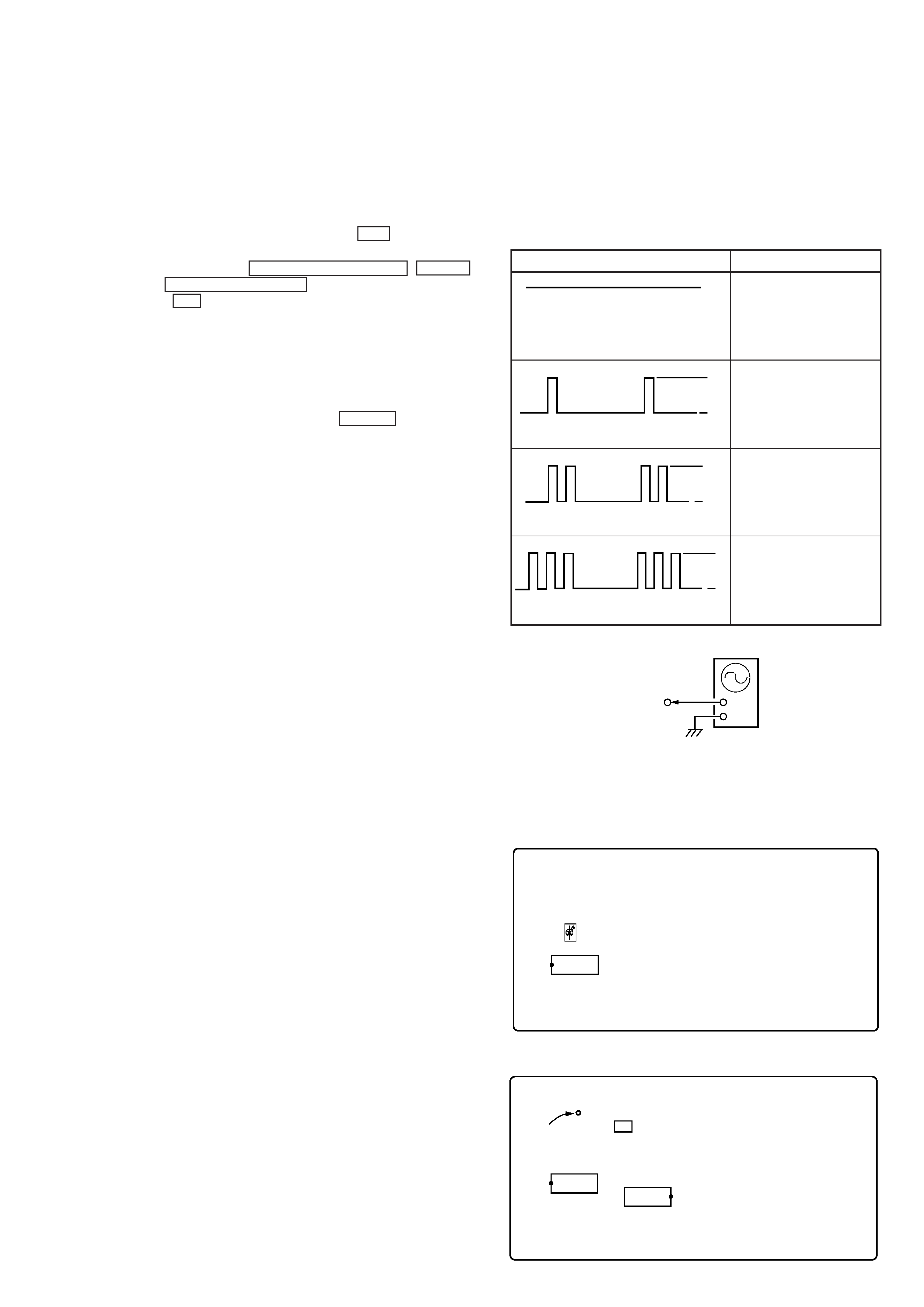
SELF-DIAGNOSIS
This model has the self-diagnosis function for the VIDEO and
AUDIO decoder sections.
Immediately after the power on, the self-diagnosis function searches
each operation of IC's around the mechanism control microcom-
puter (IC701).
The results can be checked by connecting an oscilloscope to TP709
(LED) of the VIDEO board.
Oscilloscope (Waveform)
Symptom
H
L
Light
H
L
1 time blinking
H
L
3 time blinking
No error
DRAM (IC251) error
H
L
2 time blinking
External SRAM (IC751)
error
MPEG decoder (IC201)
error
oscilloscope
VIDEO board
TP709 (LED)
+
Note: The LED for check (D701) is mounted to some sets
(FORMER TYPE). In this case, confirm the lighting condi-
tion of LED.
[VIDEO BOARD] (SIDE A)
[VIDEO BOARD] (SIDE B)
X901
TP709 (LED)
IC751
IC251
D701
IC771