HCD-V5500
E Model
Chinese Model
SERVICE MANUAL
STEREO CASSETTE DECK CD PLAYER
MICROFILM
Model Name Using Similar Mechanism
HCD-V8800
CD
CD Mechanism Type
CDM38-5BD21
Section
Base Unit Name
BU-5BD21
Optical Pick-up Type
KSS-213B/S-N
Tape deck
Model Name Using Similar Mechanism
HCD-V8800
Section
Tape Transport Mechanism Type
TCM-220WR2E
Manufactured under license from Dolby Laboratories
Licensing Corporation.
"DOLBY" and the double-D symbol
a are trademarks
of Dolby Laboratories Licensing Corporation.
SPECIFICATIONS
· HCD-V5500 is the deck, CD section
in MHC-V5500/V7700AV.
VIDEO CD/CD player section
System
Compact disc and digital
audio system
Laser
Semiconductor laser
(
=780nm)
Emission duration:
continuous
Laser output
Max.44.6
µW*
*This output is the value
measured at a distance of
200 mm from the
objective lens surface on
the Optical Pick-up Block
with 7 mm aperture.
Audio
Frequency response
2 Hz - 20 kHz(±0.5 dB)
Wavelength
780 - 790 nm
Signal-to-noise ratio More than 90 dB
Dynamic range
More than 90 dB
Video
Color system format NTSC, PAL
CD OPTICAL DIGITAL OUT
(Square optical connector jack, rear panel)
Wavelength
600 nm
Output Level
18 dBm
Tape player section
Recording system
4-track 2-channel stereo
Frequency response 60 - 13,000 Hz (±3 dB),
(DOLBY NR OFF) using
Sony TYPE I cassette
60 - 14,000 Hz (±3 dB),
using Sony TYPE II
cassette
Design and specifications are subject to change
without notice.

-- 2 --
TABLE OF CONTENTS
1.
SERVICING NOTE ······················································ 3
2.
GENERAL ······································································ 4
3.
DISASSEMBLY
3-1.
Back Panel, CD Block Removal ········································· 5
3-2.
Cassette Lid (A)/(B) Assy, Mechanism Deck Removal ···· 5
3-3.
Main Board, Resistor Board, Video Board,
Video In Board, Front Panel Assy Removal ······················· 6
4.
TEST MODE ·································································· 7
5.
ADJUSTMENTS
5-1.
Mechanical Adjustment ······················································ 8
5-2.
Electrical Adjustment ························································· 8
6.
DIAGRAMS
6-1.
Block Diagram -- CD Section -- ···································· 13
6-2.
Block Diagram -- Video Section -- ································ 15
6-3.
Block Diagram -- Deck/System Control Section -- ······· 17
6-4.
Circuit Boards Location ··················································· 19
6-5.
Schematic Diagram -- Audio Section -- ························· 20
6-6.
Printed Wiring Board -- Audio Section -- ······················ 23
6-7.
Printed Wiring Board -- Video Section -- ······················ 26
6-8.
Schematic Diagram -- Video Section -- ························· 29
6-9.
Schematic Diagram -- Main Section -- ·························· 33
6-10. Printed Wiring Board -- Main Section -- ······················· 37
6-11. Printed Wiring Board -- CD Panel Section -- ················ 40
6-12. Schematic Diagram -- CD Panel Section -- ··················· 43
6-13. Printed Wiring Board -- BD Section -- ·························· 45
6-14. Schematic Diagram -- BD Section -- ····························· 47
6-15. Schematic Diagram -- Motor Section -- ························ 49
6-16. Printed Wiring Board -- Motor Section -- ······················ 51
6-17. IC Block Diagrams ··························································· 53
6-18. IC Pin Functions ······························································· 57
7.
EXPLODED VIEWS
7-1.
MAIN SECTION ····························································· 69
7-2.
FRONT PANEL SECTION ·············································· 70
7-3.
CD MECHANISM DECK SECTION
(CDM38-5BD21) ····························································· 71
7-4.
CD MECHANISM DECK SECTION-2
(CDM38-5BD21) ····························································· 72
7-5.
BASE UNIT SECTION (BU-5BD21) ····························· 73
7-6.
TAPE MECHANISM DECK SECTION-1
(TCM-220WR2E) ···························································· 74
7-7.
TAPE MECHANISM DECK SECTION-2
(TCM-220WR2E) ···························································· 75
8.
ELECTRICAL PARTS LIST ··································· 76
-- 3 --
SECTION 1
SERVICING NOTE
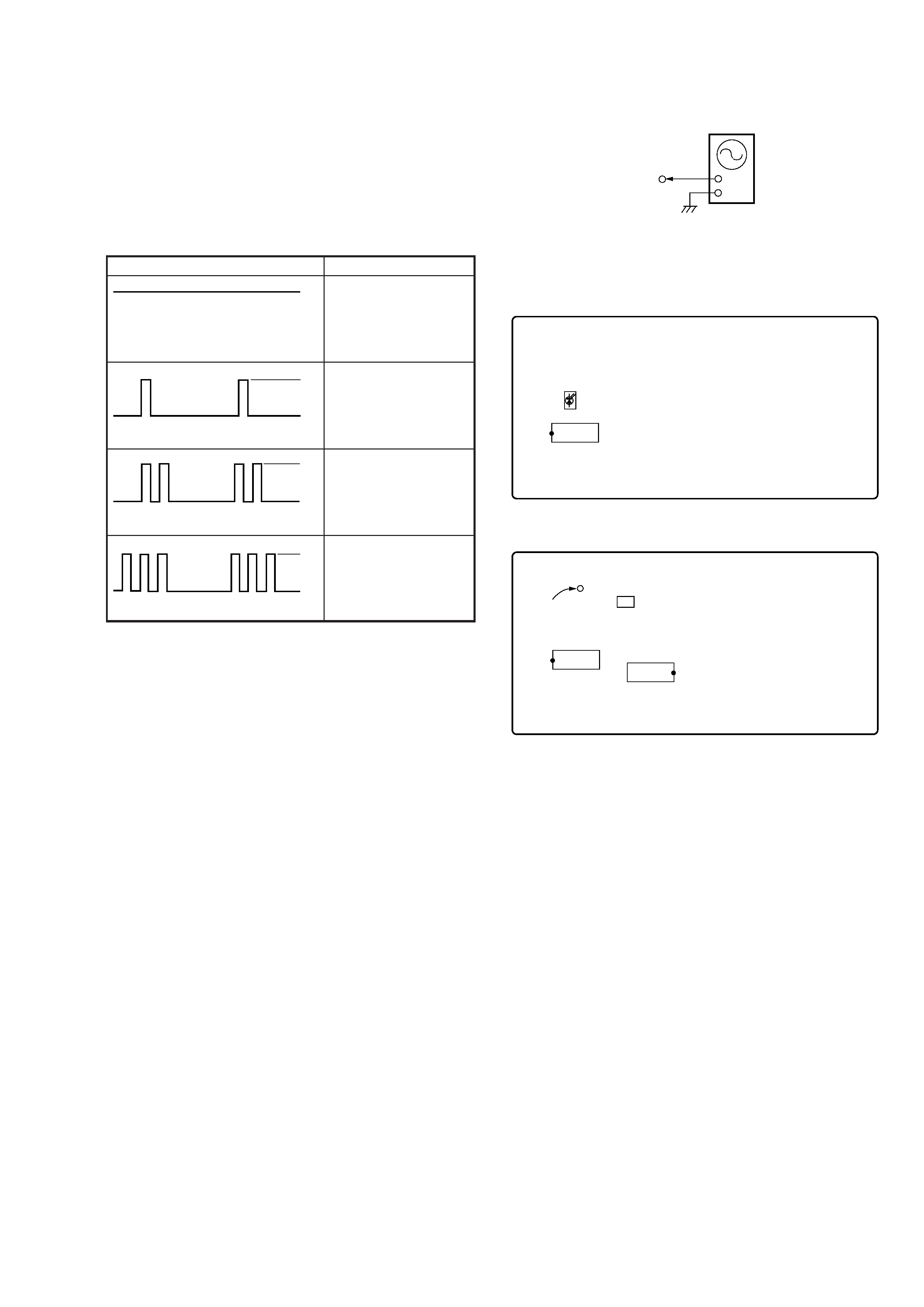
SELF-DIAGNOSIS
This model has the self-diagnosis function for the VIDEO and
AUDIO decoder sections.
Immediately after the power on, the self-diagnosis function searches
each operation of IC's around the mechanism control microcomputer
(IC701).
The results can be checked by connecting an oscilloscope to TP709
(LED) of the VIDEO board.
Note: The LED for check (D701) is mounted to some sets
(FORMER TYPE). In this case, confirm the lighting
condition of LED.
[VIDEO BOARD] (SIDE A)
[VIDEO BOARD] (SIDE B)
Oscilloscope (Waveform)
Symptom
No error
External SRAM (IC751)
error
MPEG decoder (IC201)
error
DRAM (IC251)
error
H
L
Light
H
L
1 time blinking
H
L
2 time blinking
H
L
3 time blinking
VIDEO board
TP709 (LED)
Oscilloscope
+
_
D701
IC771
TP709 (LED)
X901
IC751
IC251
-- 4 --
SECTION 2
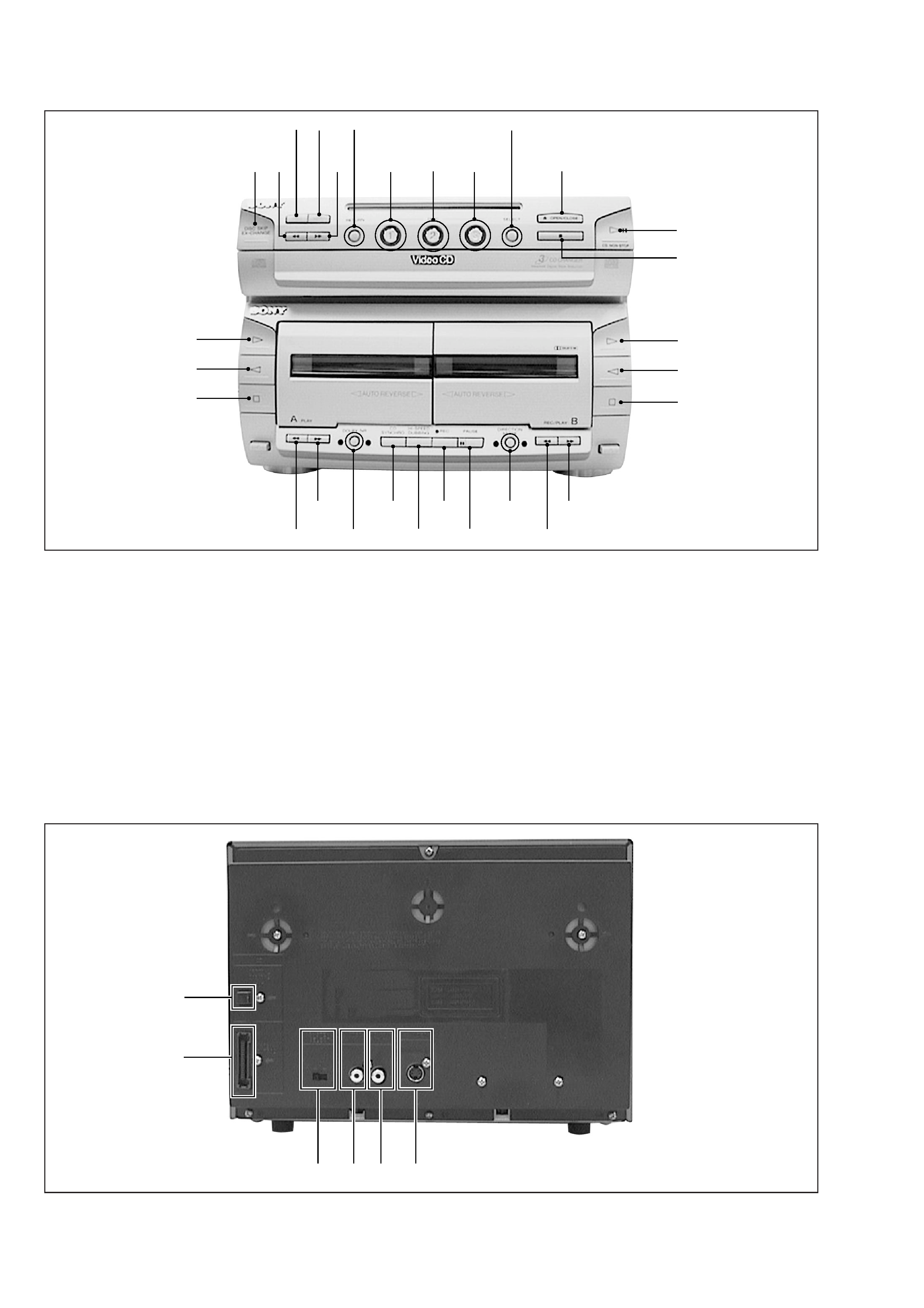
GENERAL
1 DISC SKIP EX-CHANGE Button
(CD)
2 0 Button (CD)
3 PREV Button (CD)
4 NEXT Button (CD)
5 ) Button (CD)
6 RETURN Button (CD)
7 DISC 1 Button (CD)
8 DISC 2 Button (CD)
9 DISC 3 Button (CD)
!º SELECT Button (CD)
!¡ 6 OPEN/CLOSE Button (CD)
!TM ·P CD NON-STOP Button (CD)
!£ p Button (CD)
!¢ · Button [B] (DECK)
! ª Button [B] (DECK)
!§ Button [B] (DECK)
!¶ ) Button [B] (DECK)
!· 0 Button [B] (DECK)
!ª DIRECTION MODE Button
(DECK)
@º PAUSE Button (DECK)
#º
#¡
#TM
#£ #¢
#
12
5
7
8
9
!¡
!TM
!£
!¢
!
!§
!¶
!·
!ª
@º
@¡
@TM
@£
@¢
@
@§
@¶
@·
@ª
3 4
6
!º
@¡ REC Button (DECK)
@TM HI-SPEED DUBBING Button
(DECK)
@£ CD SYNCHRO Button (DECK)
@¢ DOLBY NR Button (DECK)
@ ) Button [A] (DECK)
@§ 0 Button [A] (DECK)
@¶ Button [A] (DECK)
@· ª Button [A] (DECK)
@ª · Button [A] (DECK)
#º OPTICAL DIGITAL OUT
#¡ SYSTEM CONTROL CONNECTOR
#TM SYSTEM SELECT SWITCH
#£ VIDEO IN JACK
#¢ MONITOR OUT JACK
# S VIDEO JACK
-- 5 --
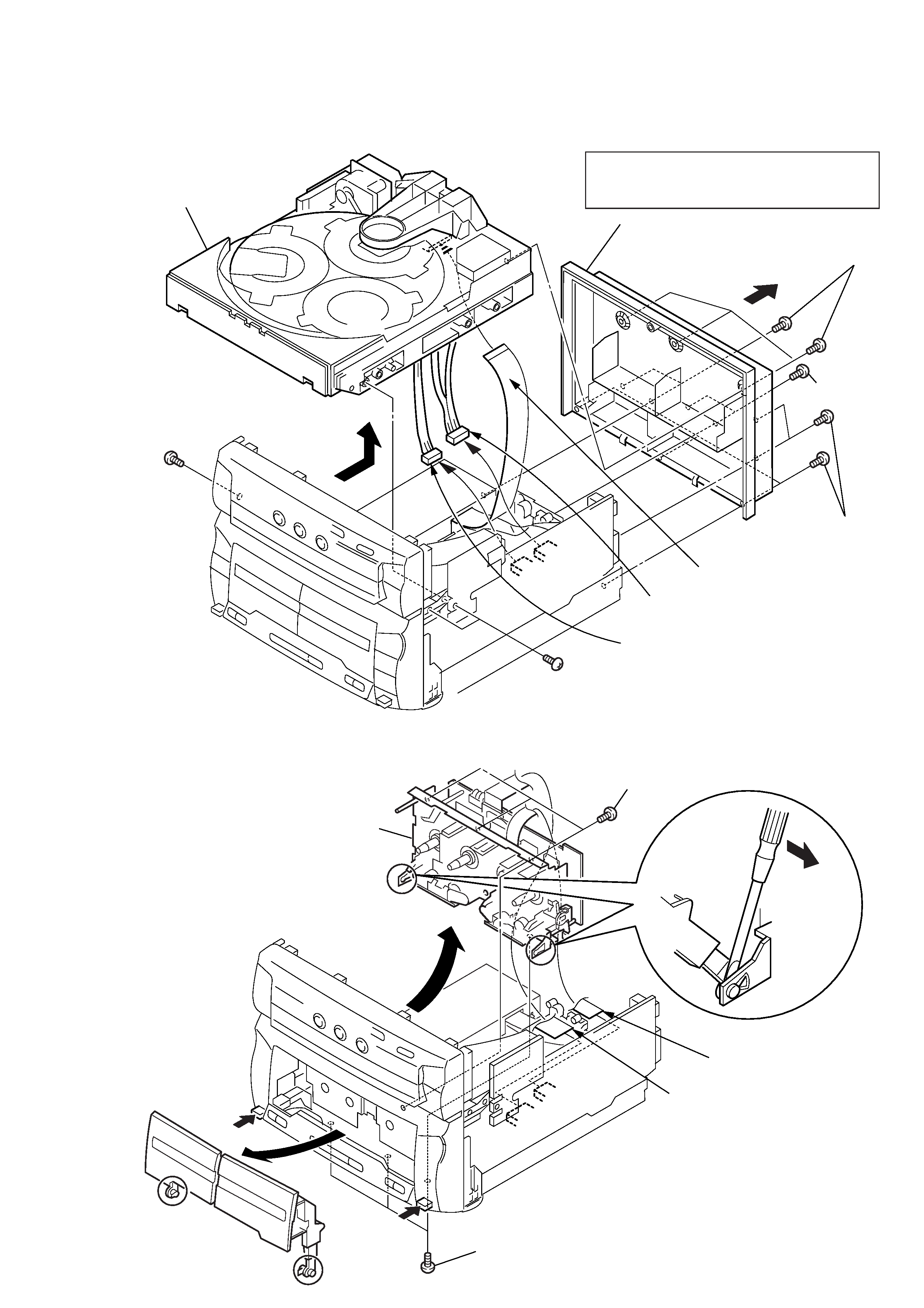
SECTION 3
DISASSEMBLY
Note :
Follow the disassembly procedure in the numerical order given.
CASE
Unscrew the five case attachment in the screws (case)
(M3
× 8) × 4, (+BV 3 × 8) × 1 and remove the case.
3-1.
BACK PANEL, CD BLOCK REMOVAL
8 Screw
+BVTP 3
× 10
1 Screw
+BVTP 3
× 10
1 Screw
+BVTP 3
× 10
7 Screw
+BVTP 3
× 10
6 CN111 (8 pin)
5 CN112 (9 pin)
4 Flat wire (19 core)
9 CD block
3 Back panel
2 Screw
+BVTP 3
× 8
3-2.
CASSETTE LID (A)/(B) ASSY, MECHANISM DECK REMOVAL
1
Press the EJECT button and open the cassette lid.
6 Screw
+BVTT 3
× 8
7 Screw
+BVTP 2.6
× 8
4 Flat wire (11 core)
5 Flat wire (21 core)
Mechanism Deck (TCM-220WR2E)
2
8
1
1
3