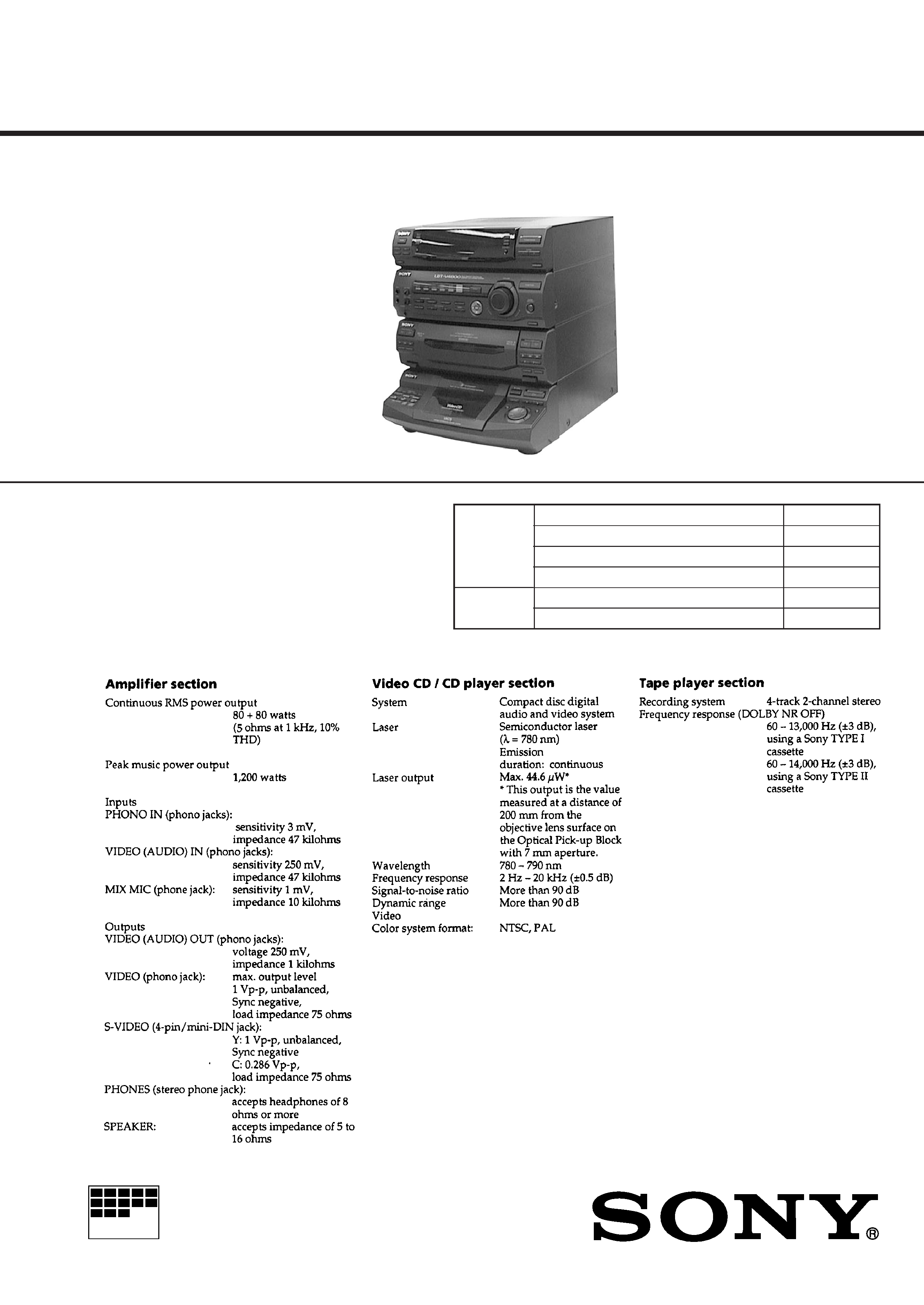
MINI Hi-Fi COMPONENT SYSTEM
MICROFILM
E Model
Chinese Model
SPECIFICATIONS
SERVICE MANUAL
HCD-V4800
HCD-4800 is the tuner, deck, Video CD and
amplifier section in LBT-V4800/V4800R.
CD
Section
Tape deck
Section
Model Name Using Similar Mechanism
HCD-V3500
CD Mechanism Type
CDM37L-5BD21AL
Base Unit Name
BU-5BD21AL
Optical Pick-up Name
KSS-213D/Q-NP
Model Name Using Similar Mechanism
HCD-V808
Tape Transport Mechanism Type
TCM-220WR2
*
Dolby noise reduction manufactured under
license from Dolby Laboratories
Licensing Corporation.
"DOLBY" and the double-D symbol
a
are trademarks of Dolby Laboratories
Licensing Corporation.
Continued on next page
2
SAFETY-RELATED COMPONENT WARNING!!
COMPONENTS IDENTIFIED BY MARK
! OR DOTTED LINE
WITH MARK
! ON THE SCHEMATIC DIAGRAMS AND IN
THE PARTS LIST ARE CRITICAL TO SAFE OPERATION.
REPLACE THESE COMPONENTS WITH SONY PARTS WHOSE
PART NUMBERS APPEAR AS SHOWN IN THIS MANUAL
OR IN SUPPLEMENTS PUBLISHED BY SONY.
CAUTION
Use of controls or adjustments or performance of procedures
other than those specified herein may result in hazardous ra-
diation exposure.
This appliance is classified as a CLASS 1 LASER product.
The CLASS 1 LASER PRODUCT MARKING is located on
the rear exterior.
Laser component in this product is capable of emitting radiation
exceeding the limit for Class 1.
The following caution label is located inside the unit.
MODEL IDENTIFICATION
BACK PANEL
MODEL
PART NO.
Singapore
4-992-219-0
Malaysia, Thai
4-992-219-1
Chinese
4-992-219-2
Indonesia
4-992-219-3
PART No.

3
TABLE OF CONTENTS
1.
GENERAL ............................................................
4
2.
DISASSEMBLY ...................................................
7
3.
TEST MODE .......................................................
15
4.
MECHANICAL ADJUSTMENTS .................... 18
5.
ELECTRICAL ADJUSTMENTS
DECKSection ...........................................................
18
CDSection
...............................................................
21
VIDEOSection
.........................................................
22
6.
DIAGRAMS
6-1.
ICPinFunctionDescription
.......................................
23
6-2.
Printed WiringBoar d--BDSection--
........................
33
6-3.
SchematicDiagram--BDSection--
...........................
35
6-4.
Printed WiringBoar ds--CDMO TORSection--
......... 37
6-5.
Sc hematicDia gram--CDMO TORSection--
............. 39
6-6.
Printed WiringBoar ds--VIDEOSection--
................. 42
6-7.
SchematicDiagram--VIDEOSection--
..................... 45
6-8.
SchematicDiagram--DECKSection--
......................
51
6-9.
Printed WiringBoar ds--DECKSection--
.................. 55
6-10. Printed WiringBoar ds
--MAIN/DECK/POWER SUPPL Y Section--
............. 58
6-11. SchematicDiagram
--MAIN/POWER SUPPL Y Section--
........................
61
6-12. Sc hematicDia gram--P ANELSection-- ..................... 68
6-13. Printed WiringBoar ds--P ANELSection-- ................. 71
6-14. SchematicDiagram
--POWER AMP/KEY CONTR OL Section--
.............. 74
6-15. Printed WiringBoar ds
--POWER AMP/KEY CONTR OL Section--
.............. 77
7.
EXPLODED VIEWS ..........................................
88
8.
ELECTRICAL PARTS LIST .............................
97
SERVICING NOTES
The laser diode in the optical pick-up block may suffer electro-
static break-down because of the potential difference generated
by the charged electrostatic load, etc. on clothing and the human
body.
During repair, pay attention to electrostatic break-down and also
use the procedure in the printed matter which is included in the
repair parts.
The flexible board is easily damaged and should be handled with
care.
NOTES ON LASER DIODE EMISSION CHECK
The laser beam on this model is concentrated so as to be focused
on the disc reflective surface by the objective lens in the optical
pick-up block. Therefore, when checking the laser diode emis-
sion, observe from more than 30 cm away from the objective lens.
LASER DIODE AND FOCUS SEARCH OPERATION
CHECK
Carry out the "S curve check" in "CD section adjustment" and
check that the S curve waveforms is output three times.
Notes on chip component replacement
· Neverreuseadisconnectedc
hipcomponent.
· Noticethattheminussideofatantalumcapacitormaybedam-
agedbyheat.
Flexible Circuit Board Repairing
· Keepthetemperatureofthesolderingir
onar ound270°Cduring
repairing.
· Donottouchthesolderingirononthesameconductorofthe
circuitboard(within3times).
· Becarefulnottoapplyforceontheconductorwhensolderingor
unsoldering.
NOTES ON HANDLING THE OPTICAL PICK-UP
BLOCK OR BASE UNIT
4
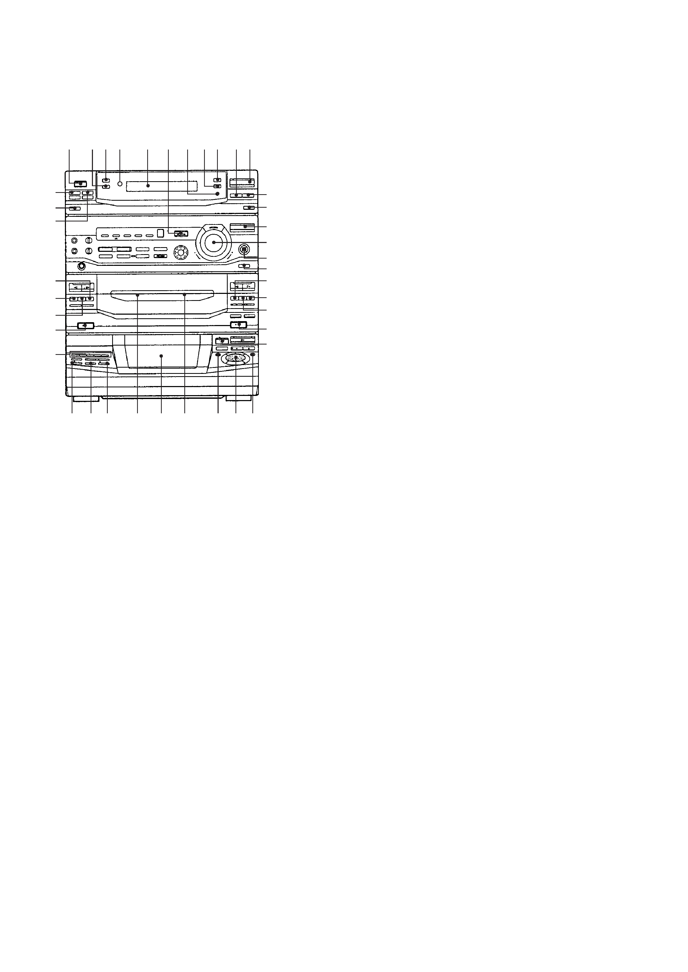
1 POWERb utton
2 SPECTR UMANALYZERb utton
3 DISPLAY/DEMObutton
4 Remotecontr olreceiver
5 Fluorescentindicatortube
6 EFFECTb uttonandindicator
7 ENTER/NEXTb uttonandindicator
8 TUNER MEMORY button
9 TUNING MODE b utton
0 TUNINGb utton
!¡ TUNER/BANDbuttonandindicator
!TM TUNING+b utton
!£ STEREO/MONOb utton
!¢ FUNCTIONb utton
!
VOLUMEcontr olknob
!§ SUPER WOOFERb uttonandindicator
!¶ SUPER WMODEb utton
!· pbutton(dec kBside)
!ª )button (dec kBside)
@º 0button(dec kBside)
@¡ §EJECTb utton(dec kBside)
@TM 6OPENb utton
@£ t/CLOCKSETb utton
@¢ SLEEPb utton
@
RECb utton
@§ )button (dec kAside)
@¶ pbutton(dec kAside)
@· 0button(dec kAside)
@ª §EJECTb utton(dec kAside)
#º DIRECT PLAY DISC 1 to DISC 5 b uttons
#¡ ^RETURNb utton
#TM PREVb utton
#£ NEXTbutton
#¢ Cassetteholder(dec
kAside)
#
CDdisctray
#§ Cassetteholder(deckBside)
#¶ 0button
#·
AMS
±
jog dial knob
#ª )button
SECTION 1
GENERAL
LOCATION OF CONTROLS
-- Front Panel --
0 !¡
9
8
7
6
5
4
3
2
1
!TM
!£
!¢
!
!§
!¶
!·
!ª
@º
@¡
@TM
@£
@¢
@
@§
@¶
@·
@ª
#º
#¡ #TM #£
#¢ #
#§
#¶ #· #ª
5
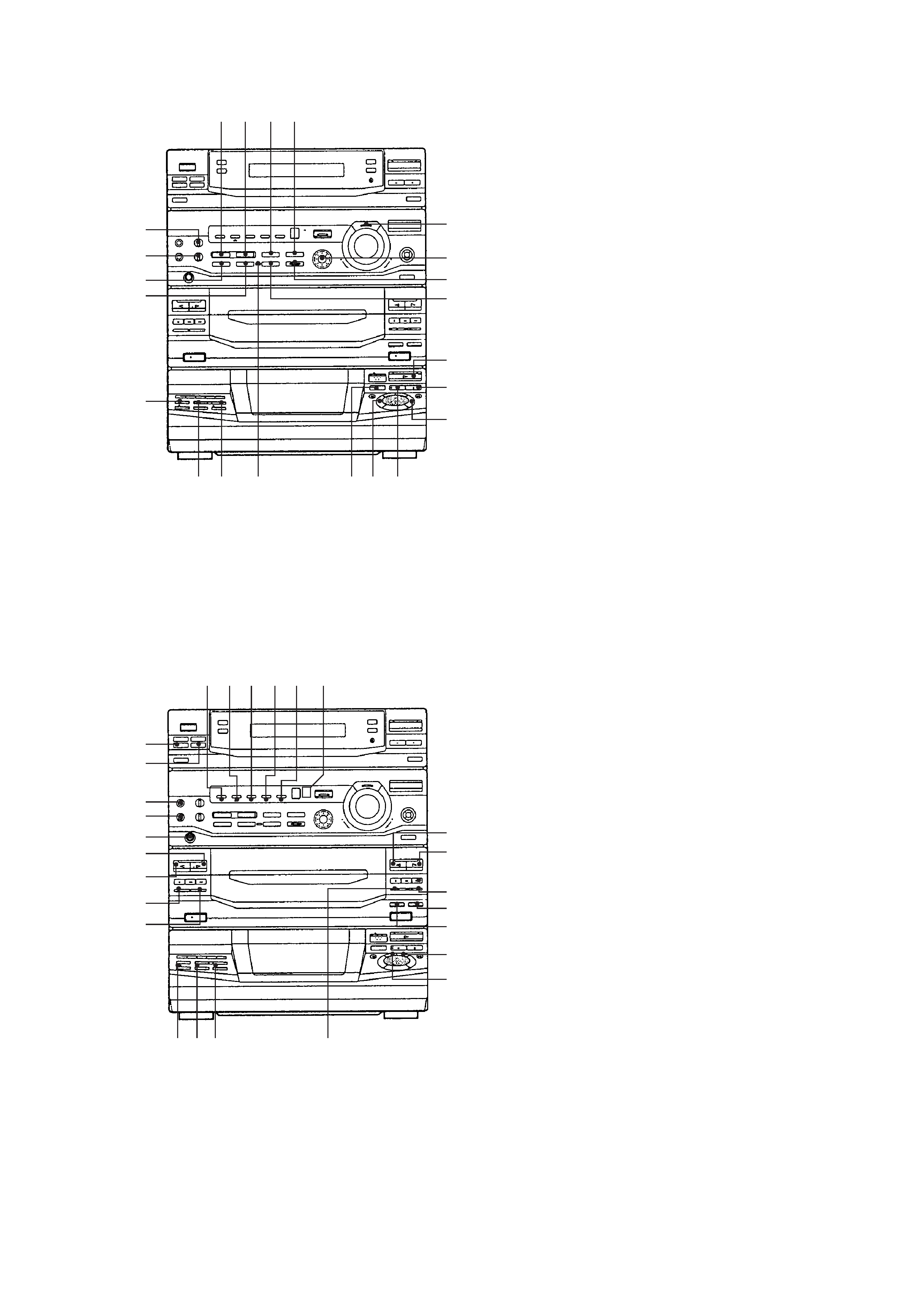
$º SOUNDCONTR OLWAVEbutton
$¡ SOUNDCONTR OLSURR OUNDb utton
$TM P FILE MEMOR Y button
$£ GEQCONTR OLb utton
$¢ GROOVEbuttonandindicator
$
GEQcursorcontrol
$§ ENTERb uttonandindicator
$¶ KEY CONTR OL nbutton
$· ·buttonandindicator
$ª pbutton
%º REPEA Tbutton
%¡ MICLEVELcontrolknob
%TM ECHOLEVELcontrolknob
%£ KARAOKEPON/MPXb utton
%¢ KEY CONTR OL ~button
%
CDNON-ST OPb uttonandindicator
%§ DJ MIX CD LOOP b utton
%¶ DJ MIX CD FLASH b utton
%· KEYCONTR OLindicator
%ª DISCSKIPb utton
^º EDITbutton
^¡ Pbuttonandindicator
^TM FILE 1/MOVIE/ROCK indicator
^£ FILE2/GAME/POPindicator
^¢ FILE3/NIGHT/J AZZindicator
^
FILE4/PARTY/DANCEindicator
^§ FILE5/RELAX/SALSAindicator
^¶ P FILE/MENU 2/MENU 1 indicator
^· ªbuttonandindicator(dec
kBside)
^ª ·buttonandindicator(dec
kBside)
&º rRECb uttonandindicator
&¡ CDSYNCb utton
&TM HSPEEDDUBb utton
&£ PLAYMODEb utton
&¢ 1/ALLDISCSb utton
&
DAILY1button
&§ DAILY 2 b utton
&¶ MIC 1 jack
&· MIC 2 jack
&ª PHONESjack
*º ·buttonandindicator(dec
kAside)
*¡ ªbuttonandindicator(dec
kAside)
*TM DIRECTIONb utton
*£ DOLBYNRb utton
*¢ VCDindicator
*
PBCindicator
*§ AUTOPBCindicator
*¶ PPAUSEb uttonandindicator
$º $¡ $TM $£
$¢
$
$§
$¶
$·
$ª
%º
^¡
^º
%ª
%·
%¶
%§
%
%¢
%£
%TM
%¡
^TM ^£ ^¢ ^
^§ ^¶
^·
^ª
&º
&¡
&TM
&£
&¢
*¶
*§
*
*¢
*£
*TM
*¡
*º
&ª
&·
&¶
&§
&