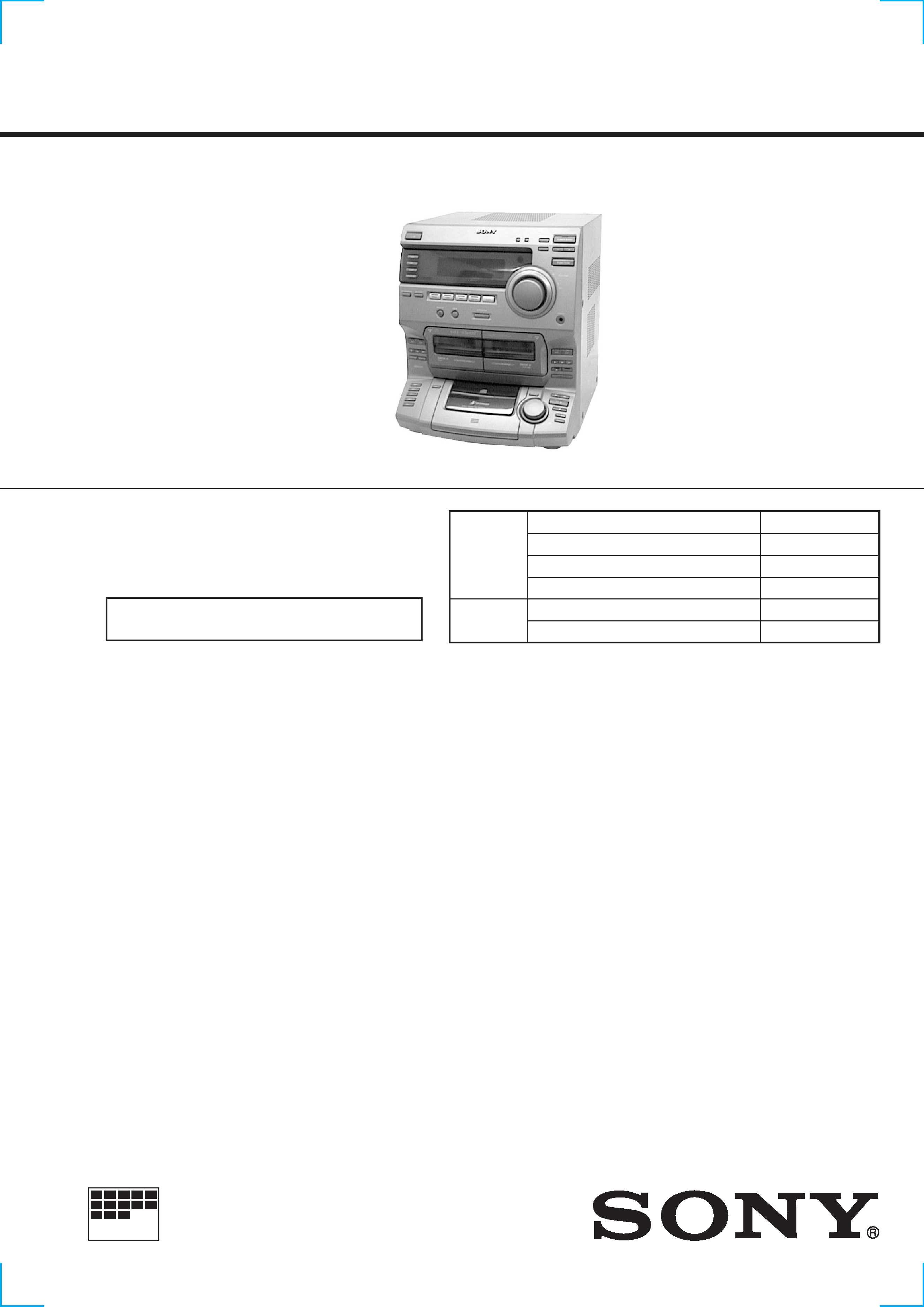
HCD-S3000
US Model
Canadian Model
SERVICE MANUAL
COMPACT Hi-Fi STEREO SYSTEM
MICROFILM
SPECIFICATIONS
HCD-S3000 is the tuner, deck, CD and
amplifier section in LBT-S3000.
Model Name Using Similar Mechanism
HCD-G2500
CD Mechanism Type
5CD DISC
Base Unit Type
KSM-213ECM
Optical Pick-up Type
KSS-213ECM/C2NP
Model Name Using Similar Mechanism
NEW
Tape Transport Mechanism Type
CWL-44-RR
CD
SECTION
TAPE
DECK
SECTION
Manufactured under license from Dolby Laboratories
Licensing Corporation.
"DOLBY" and the double-D symbol
aare trademarks
of Dolby Laboratories Licensing Corporation.
U.S and foreign patents licensed from Dolby
Laboratories Licensing Corporation.
-- Continued on next page --
(For the U.S model)
AUDIO POWER SPECIFICATIONS:
POWER OUTPUT AND TOTAL
HARMONIC DISTORTION:
with 6
loads both channels driven, from 70
20,000 Hz; rated 70 W per channel minimum RMS
power, with no more than 0.9% total harmonic
distortion from 250 mW to rated output.
Amplifier section
Continuous RMS power output
80W + 80W
(6
at 1 kHz, 10%
THD)
Total harmonics distortion
Less than 0.07%
(6
at 1 kHz, 35W)
Inputs
PHONO IN (phono jack):
sensitivity 3mV,
impedance 47 k
MD/VIDEO IN (phono jacks):
sensitivity 250mV,
impedance 47 k
Outputs
PHONOS (stereo phono jacks):
accepts headphones of
8 W or more
MD/VIDEO OUT (phone jack):
voltage 250mV,
impedance 1 k
SPEAKER:
accepts impedance of
6 to 16
CD player section
System
Compact disc and digital
audio system
Laser
Semiconductor laser
(
= 780 nm)
Emission
duration: continuous
Laser output
Max. 44.6µW*
*This output is the value
measured at a distance of
200 mm from the
objective lens surface on
the Optical Pock-up
Block with 7 mm
aperture.
Wavelength
780 790 nm
Frequency response
20Hz 20kHz (±0.5 dB)
Signal-to-noise retio
More than 90 dB
Dynamic range
More than 90 dB
DIGITAL OUT
(Square optical connector jack, rear panel)
Wavelength
600 nm
Output Level
18 dBm
Tape deck section
Recording system
4-track 2-channel stereo
Frequency response (DOLBY NR OFF)
60 13,000 Hz (±3 dB),
using Sony TYPE I
cassette
Tuner section
FM stereo, FM/AM superheterodyne tuner
FM tunr section
Tuning range
87.5 108.0 MHz
(100 kHz step)
AM tuner section
Tuning renge
530 1,710 kHz
(with the tuning interval
set at 10 kHz)
Antenna
AM loop antenna
External antenna
terminal
Intermediate frequency
450 kHz
-- 2 --
After correcting the original service problem, perform the following
safety checks before releasing the set to the customer:
Check the antenna terminals, metal trim, "metallized" knobs, screws,
and all other exposed metal parts for AC leakage. Check leakage as
described below.
LEAKAGE
The AC leakage from any exposed metal part to earth ground and
from all exposed metal parts to any exposed metal part having a
return to chassis, must not exceed 0.5 mA (500 microamperes).
Leakage current can be measured by any one of three methods.
1.
A commercial leakage tester, such as the Simpson 229 or RCA
WT-540A. Follow the manufacturers' instructions to use these
instruments.
2.
A battery-operated AC milliammeter. The Data Precision 245
digital multimeter is suitable for this job.
3.
Measuring the voltage drop across a resistor by means of a
VOM or battery-operated AC voltmeter. The "limit" indication
is 0.75 V, so analog meters must have an accurate low-voltage
scale. The Simpson 250 and Sanwa SH-63Trd are examples of
a passive VOM that is suitable. Nearly all battery operated
digital multimeters that have a 2V AC range are suitable. (See
Fig. A)
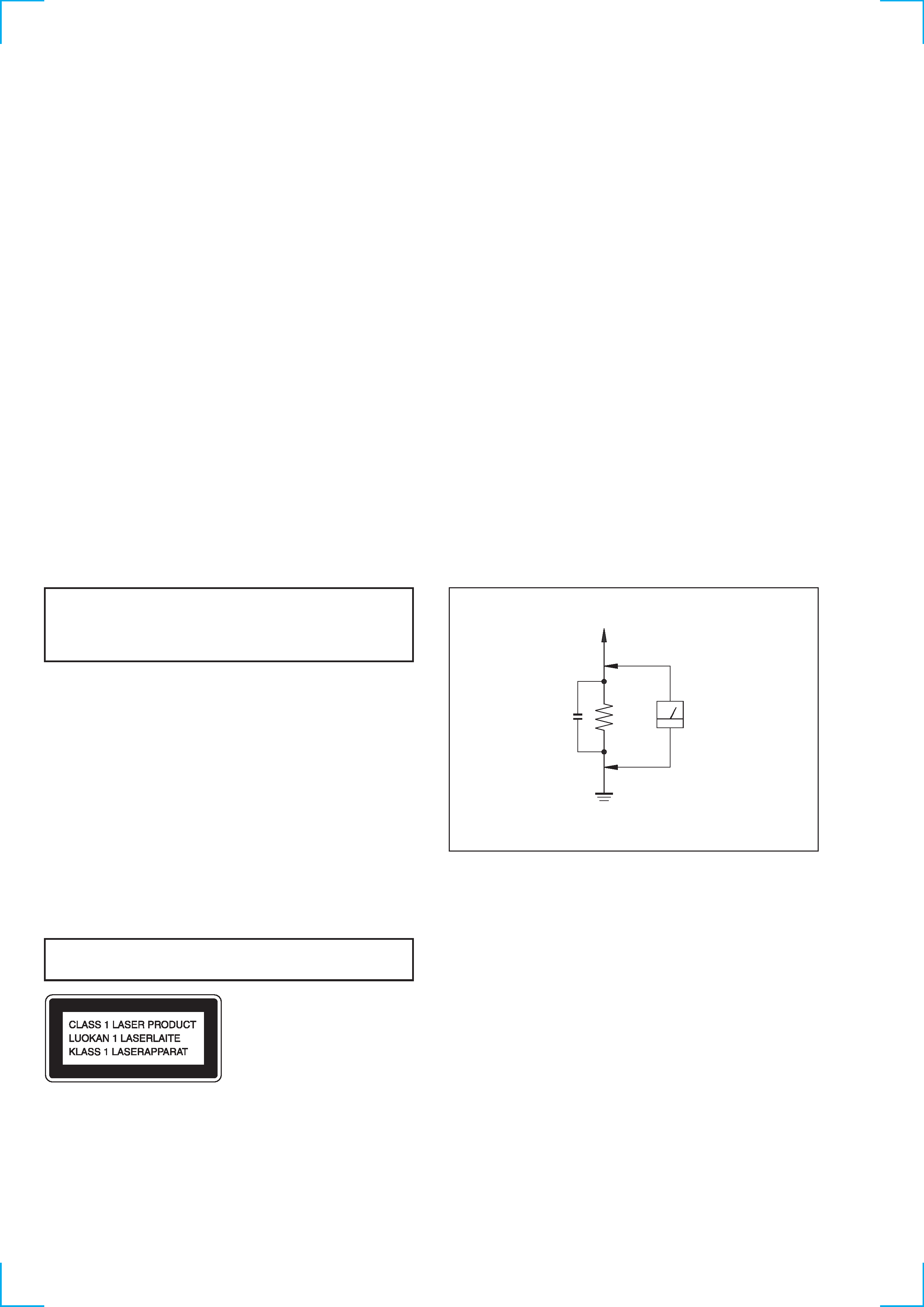
SAFETY CHECK-OUT
To Exposed Metal
Parts on Set
0.15
µF
1.5 k
AC
Voltmeter
(0.75 V)
Earth Ground
Fig. A. Using an AC voltmeter to check AC leakage.
This appliance is classified as a CLASS 1 LASER product. The
CLASS 1 LASER PRODUCT MARKING is located on the rear
exterior.
Laser component in this product is capable of emitting radiation
exceeding the limit for Class 1.
CAUTION
Use of controls or adjustments or performance of procedures
other than those specified herein may result in hazardous radiation
exposure.
Notes on chip component replacement
· Never reuse a disconnected chip component.
· Notice that the minus side of a tantalum capacitor may be
damaged by heat.
Flexible Circuit Board Repairing
· Keep the temperature of soldering iron around 270°C
during repairing.
· Do not touch the soldering iron on the same conductor of the
circuit board (within 3 times).
· Be careful not to apply force on the conductor when soldering
or unsoldering.
SAFETY-RELATED COMPONENT WARNING!!
COMPONENTS IDENTIFIED BY MARK
! OR DOTTED LINE WITH
MARK
! ON THE SCHEMATIC DIAGRAMS AND IN THE PARTS
LIST ARE CRITICAL TO SAFE OPERATION. REPLACE THESE
COMPONENTS WITH SONY PARTS WHOSE PART NUMBERS
APPEAR AS SHOWN IN THIS MANUAL OR IN SUPPLEMENTS
PUBLISHED BY SONY.
ATTENTION AU COMPOSANT AYANT RAPPORT
À LA SÉCURITÉ!
LES COMPOSANTS IDENTIFÉS PAR UNE MARQUE
! SUR LES
DIAGRAMMES SCHÉMATIQUES ET LA LISTE DES PIÈCES SONT
CRITIQUES POUR LA SÉCURITÉ DE FONCTIONNEMENT. NE
REMPLACER CES COMPOSANTS QUE PAR DES PIÈSES SONY
DONT LES NUMÉROS SONT DONNÉS DANS CE MANUEL OU
DANS LES SUPPÉMENTS PUBLIÉS PAR SONY.
General
Power requirements
120V AC, 60Hz
Power consumption
135W
Dimensions (w/h/d)
Approx. 355
× 425 × 442 mm
(14
× 163/4 × 171/2 in) incl. projecting patrs and
controls
Mass
Approx. 13.1kg (28 lb 14 oz.)
Supplied accessories:
AM loop antenna (1)
Remote RM-SG7B(1)
FM wire antenna (1)
Design and specifications are subject to change without notice.

-- 3 --
TABLE OF CONTENTS
1. GENERAL ·········································································· 4
2. DISASSEMBLY
2-1.
Top Cover ··········································································· 5
2-2.
Front Panel Assy ································································· 5
2-3.
Main Board ········································································· 6
2-4.
Main Section ······································································· 6
2-5.
CD Mechanism Deck Section ············································ 7
2-6.
Tape Mechanism Deck Section ·········································· 7
2-7.
Cassette Doors ···································································· 8
2-8.
CD Chassis Assy ································································ 8
2-9.
Base Unit ············································································ 9
2-10. Turn Table ··········································································· 9
3. MECHANICAL ADJUSTMENTS ····························· 10
4. ELECTRICAL ADJUSTMENTS ······························· 10
5. DIAGRAMS
5-1.
Ciecuit Boards Location ··················································· 15
5-2.
Block Diagrams ································································ 17
Main Section ····································································· 17
Tuner/CD Section ····························································· 19
5-3.
Printed Wiring Board
Main Section ····························· 21
5-4.
Schematic Diagram
Main (1/3) Section ······················· 23
5-5.
Schematic Diagram
Main (2/3) Section ······················· 25
5-6.
Schematic Diagram
Main (3/3) Section ······················· 27
5-7.
Printed Wiring Board
Amp Section ······························ 29
5-8.
Schematic Diagram
Amp Section ································· 31
5-9.
Printed Wiring Board
CD Decoder Section ················· 33
5-10. Schematic Diagram
CD Decoder Section ···················· 35
5-11. Printed Wiring Board
Front Section ····························· 37
5-12. Schematic Diagram
Front (1/2) Section ······················· 39
5-13. Schematic Diagram
Front (2/2) Section ······················· 41
5-14. IC Pin Function Description ············································· 43
5-15. IC Block Diagrams ··························································· 45
6. EXPLODED VIEWS
6-1.
Top Cover Section ···························································· 47
6-2.
CD Door Section ······························································ 48
6-3.
Panel Section ···································································· 49
6-4.
Main Section ····································································· 50
7. ELECTRICAL PARTS LIST ······································· 51
-- 4 --
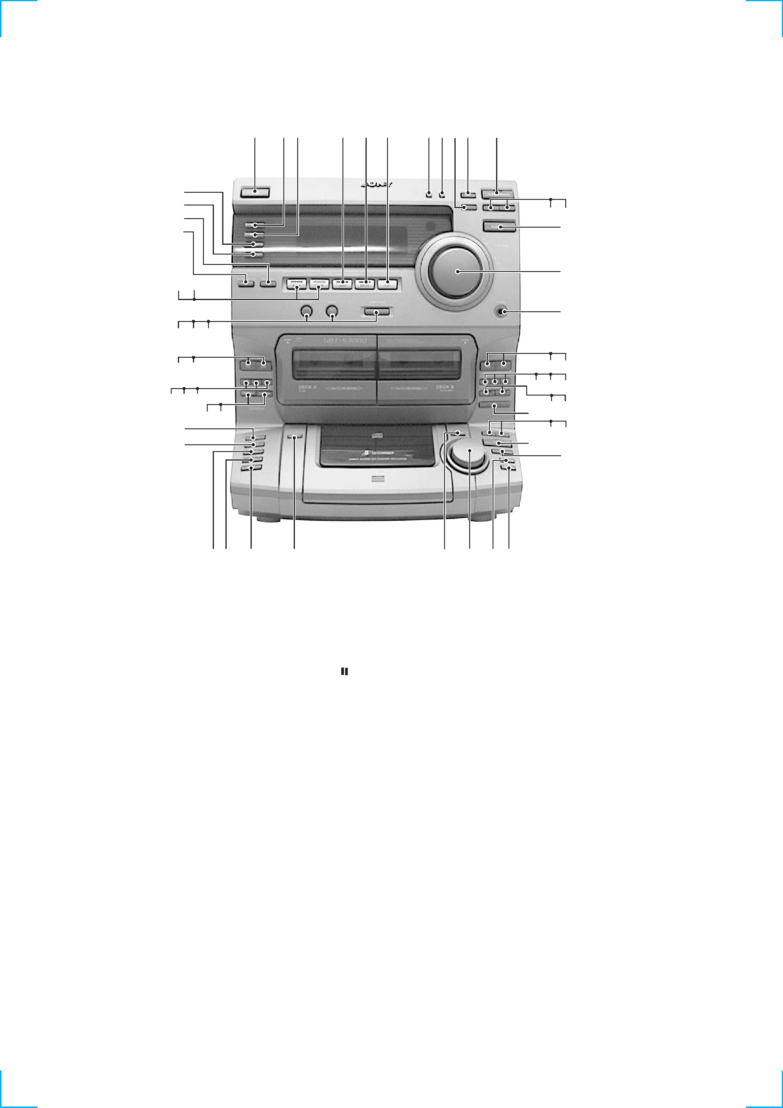
1
1/u (POWER) button
2
TUNING MODE button
3
STEREO/MONO button
4
TUNER MEMORY button
5
ENTER/NEXT button
6
TUNER/BAND button
7
TUNING button
8
TUNING + button
9
FUNCTION button
!º
VOLUME knob
!¡
PHONES jack
!TM
ª button (DECK B)
!£
· button (DECK B)
!¢
p button (DECK B)
!
0 button (DECK B)
!§
) button (DECK B)
!¶
P button (DECK B)
!·
r REC button (DECK B)
!ª
CD SYNCHRO button
@º
0 button (CD)
@¡
) button (CD)
@TM
fl button (CD)
@£
p button (CD)
@¢
REPEAT button
@
PLAY MODE button
@§
AMS knob
@¶
DISC SKIP button
@·
EDIT button
@ª
DISC 5 button
#º
DISC 4 button
#¡
DISC 3 button
#TM
DISC 2 button
#£
DISC 1 button
#¢
DIRECTION button
#
DOLBY NR button
#§
p button (DECK A)
SECTION 1
GENERAL
1
%¢ %£
23
5
4
$ª
$·
%º
6
8
9
7
!¡
%TM
%¡
#TM
#£
@TM
0
$
$¢
!£
!TM
$¶
$§
$º
#ª
$TM
$¡
$£
@¡
@º
!·
!ª
@£
!¶
!§
!
!¢
@
@¶
#º
#¡
@¢
@§
@·
@ª
#
#¢
#¶
#§
#·
#¶
0 button (DECK A)
#·
) button (DECK A)
#ª
ª button (DECK A)
$º
· button (DECK A)
$¡
GROOVE button
$TM
DBFB button
$£
SURROUND button
$¢
SPECTRUM ANALYZER button
$
DISPLAY/DEMO button
$§
ROCK button
$¶
POPS button
$·
JAZZ button
$ª
SALSA button
%º
FLAT button
%¡
t /CLOCK SET button
%TM
SLEEP button
%£
REC button
%¢
DAILY button
-- 5 --
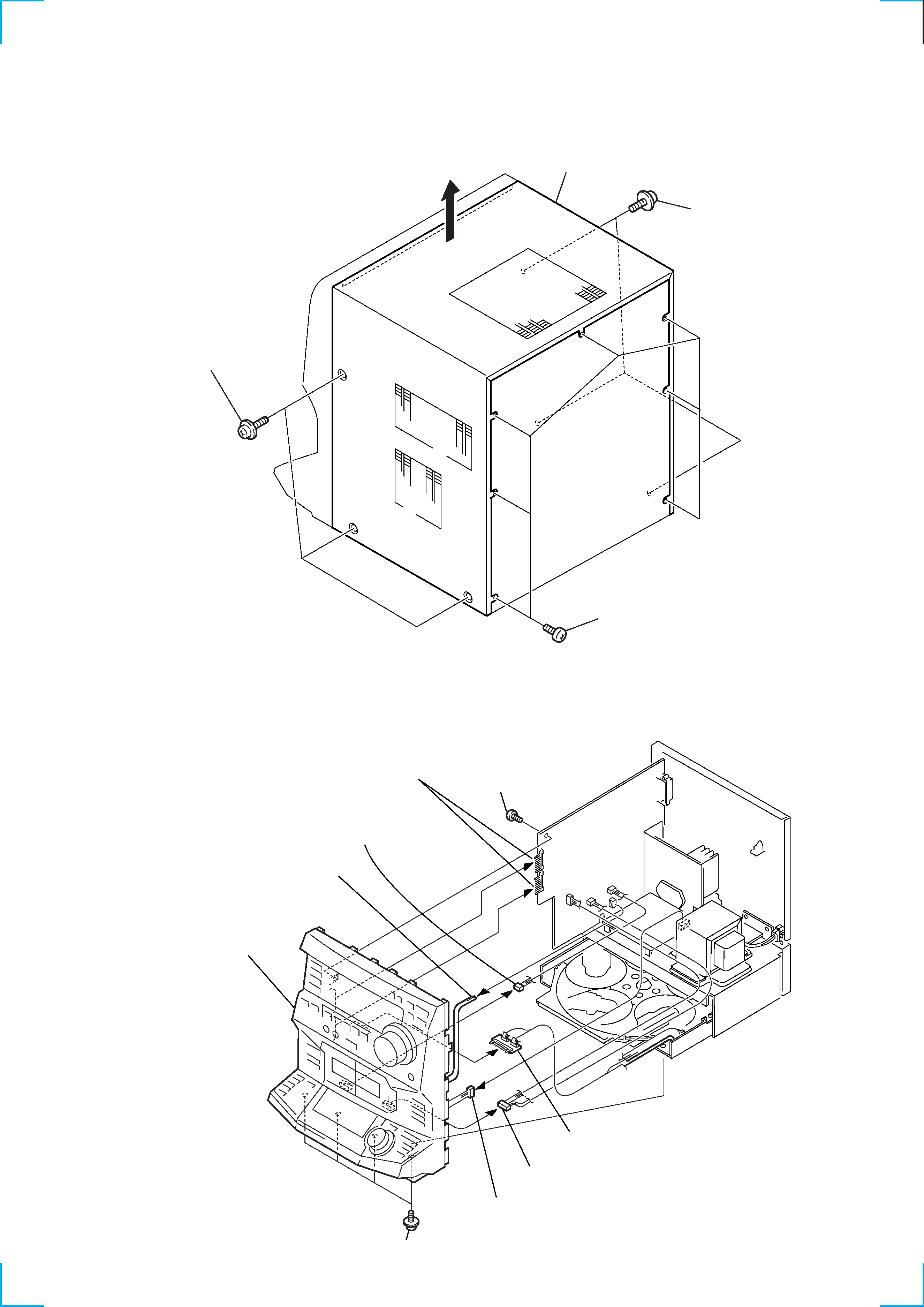
SECTION 2
DISASSEMBLY
Note :
Follow the disassembly procedure in the numerical order given.
2-1. TOP COVER
2 Seven screws
1 Three screws
1 Three screws
3 Top cover
2-2. FRONT PANEL ASSY
9 Front panel assy
6 Four screws
7 Screw
1 Connector
(to deck A)
2 Harness
(CN302)
4 Connector
(to deck B)
5 Connector
(CN702)
8 Board to board connector
(CN602)
(CN601)
3 Connector board
(CN11)