HCD-RXD2
US Model
SERVICE MANUAL
MINI Hi-Fi COMPONENT SYSTEM
MICROFILM
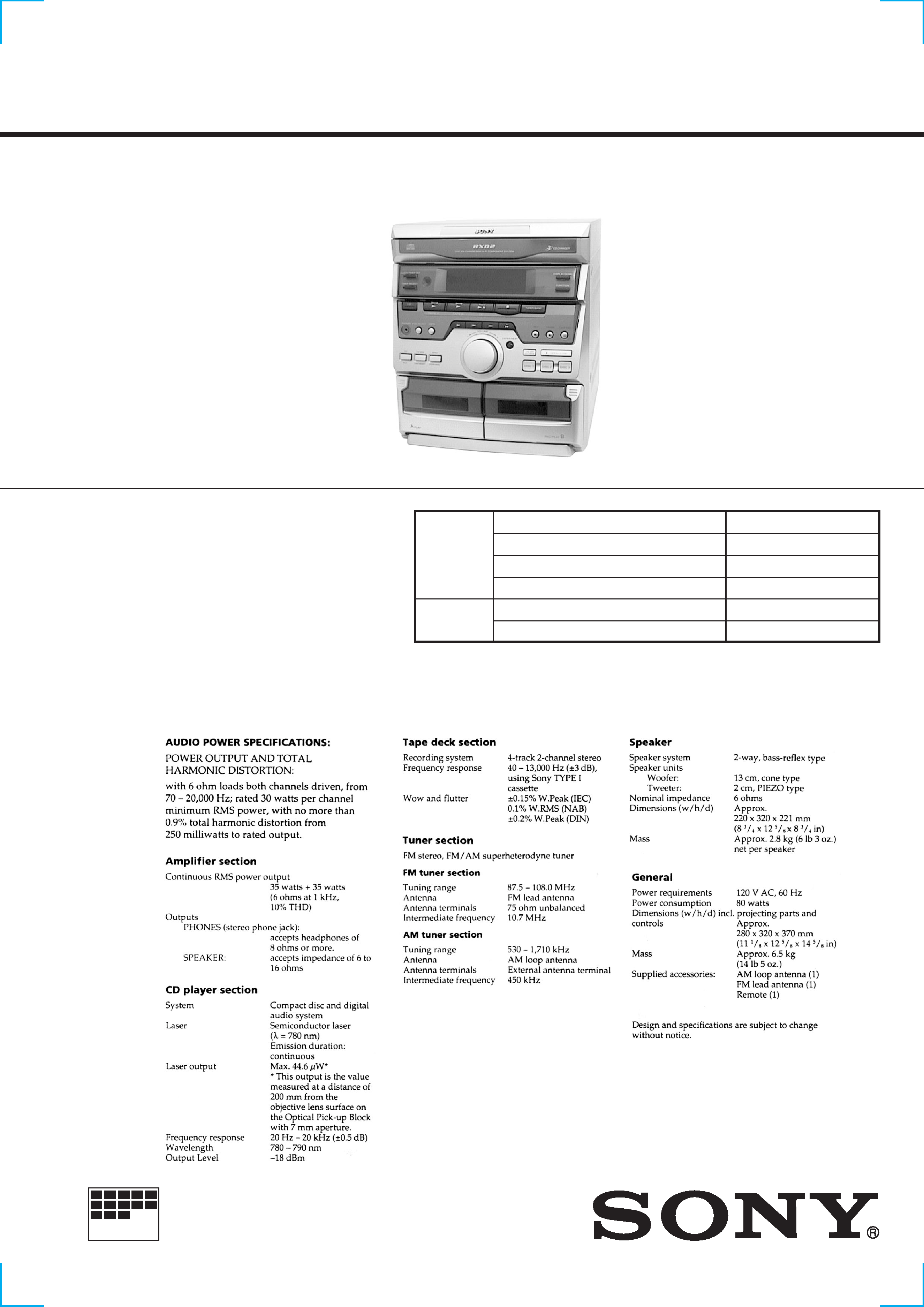
SPECIFICATIONS
HCD-RXD2 is the tuner , dec k, CD and
amplifier section in MHC-RXD2.
Model Name Using Similar Mechanism
HCD-G101
CD Mechanism Type
CX3
Base Unit Type
KSM-213ECM
Optical Pick-up Type
KSS-213ECM/C2NP
Model Name Using Similar Mechanism
NEW
Tape Transport Mechanism Type
CWL-44-FF
CD
SECTION
TAPE
DECK
SECTION
-- 2 --
After correcting the original service problem, perform the following
safety checks before releasing the set to the customer:
Check the antenna terminals, metal trim, "metallized" knobs, screws,
and all other exposed metal parts for AC leakage. Check leakage as
described below.
LEAKAGE
The AC leakage from any exposed metal part to earth ground and
from all exposed metal parts to any exposed metal part having a
return to chassis, must not exceed 0.5 mA (500 microamperes).
Leakage current can be measured by any one of three methods.
1.
A commercial leakage tester, such as the Simpson 229 or RCA
WT-540A. Follow the manufacturers' instructions to use these
instruments.
2.
A battery-operated AC milliammeter. The Data Precision 245
digital multimeter is suitable for this job.
3.
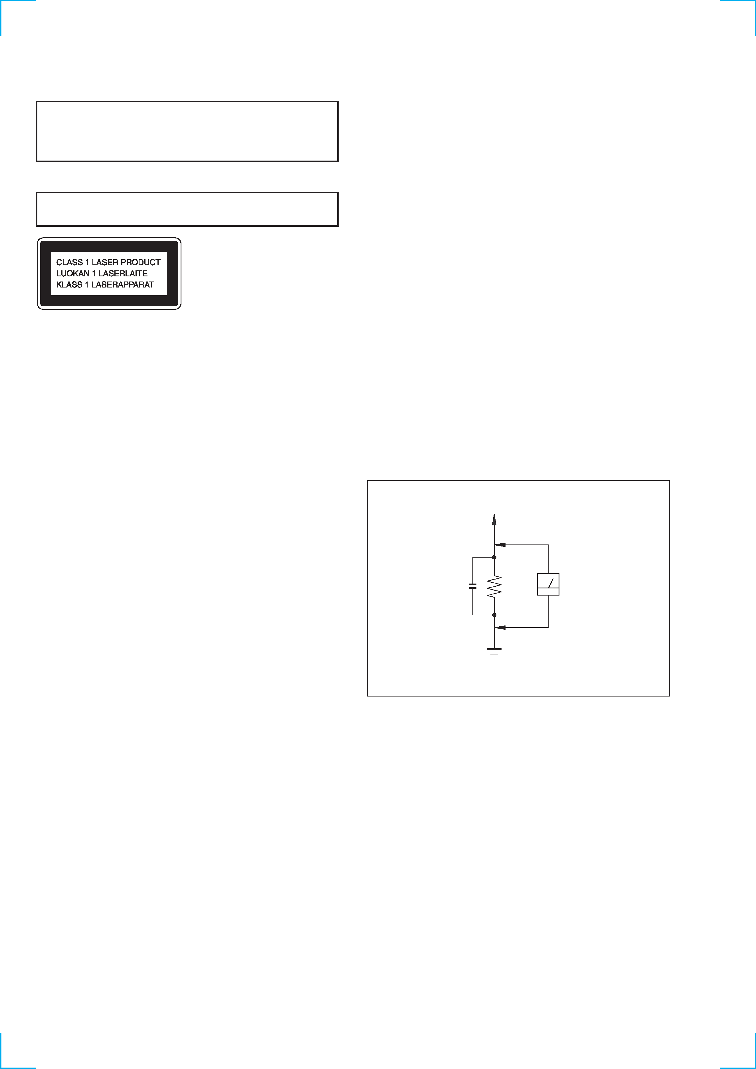
Measuring the voltage drop across a resistor by means of a
VOM or battery-operated AC voltmeter. The "limit" indication
is 0.75 V, so analog meters must have an accurate low-voltage
scale. The Simpson 250 and Sanwa SH-63Trd are examples of
a passive VOM that is suitable. Nearly all battery operated
digital multimeters that have a 2V AC range are suitable. (See
Fig. A)
SAFETY CHECK-OUT
To Exposed Metal
Parts on Set
0.15
µF
1.5 k
AC
Voltmeter
(0.75 V)
Earth Ground
Fig. A. Using an AC voltmeter to check AC leakage.
This appliance is classified as a CLASS 1 LASER product. The
CLASS 1 LASER PRODUCT MARKING is located on the rear
exterior.
Laser component in this product is capable of emitting radiation
exceeding the limit for Class 1.
CAUTION
Use of controls or adjustments or performance of procedures
other than those specified herein may result in hazardous radiation
exposure.
SAFETY-RELATED COMPONENT WARNING!!
COMPONENTS IDENTIFIED BY MARK
! OR DOTTED LINE WITH
MARK
! ON THE SCHEMATIC DIAGRAMS AND IN THE PARTS
LIST ARE CRITICAL TO SAFE OPERATION. REPLACE THESE
COMPONENTS WITH SONY PARTS WHOSE PART NUMBERS
APPEAR AS SHOWN IN THIS MANUAL OR IN SUPPLEMENTS
PUBLISHED BY SONY.

-- 3 --
TABLE OF CONTENTS
1. GENERAL ·········································································· 4
2. DISASSEMBLY
2-1.
CD Door ············································································· 5
2-2.
CD Mechanism Deck ························································· 6
2-3.
Front Panel ········································································· 6
2-4.
Main Board ········································································· 7
2-5.
Front Board ········································································· 7
2-6.
CD Tray ·············································································· 8
2-7.
CD Decord Board ······························································· 8
2-8.
Base Unit ············································································ 9
2-9.
Cassette Lid (L) / (R) ·························································· 9
3. TEST MODE ···································································· 10
4. MECHANICAL ADJUSTMENTS ····························· 11
5. ELECTRICAL ADJUSTMENTS ······························· 11
6. DIAGRAMS
6-1.
Circuit Boards Location ··················································· 16
6-2.
Block Diagrams ································································ 17
· Tuner, CD Section ························································· 17
· Main Section ·································································· 19
6-3.
Printed Wiring Board CD Decoder Section ··············· 23
6-4.
Schematic Diagram CD Decoder Section ·················· 25
6-5.
Printed Wiring Board Front Section ··························· 27
6-6.
Schematic Diagram Front Section ······························ 29
6-7.
Printed Wiring Board Main Section ··························· 31
6-8.
Schematic Diagram Main (1/4) Section ······················ 33
6-9.
Schematic Diagram Main (2/4) Section ····················· 35
6-10. Schematic Diagram Main (3/4) Section ····················· 37
6-11. Schematic Diagram Main (4/4) Section ····················· 39
6-12. IC Pin Function ································································ 41
6-13. IC Block Diagrams ··························································· 43
7. EXPLODED VIEWS
7-1.
Cabinet Section ································································· 47
7-2.
Front Panel Section ·························································· 48
7-3.
CD Mechanism Deck Section-1 ······································· 49
7-4.
CD Mechanism Deck Section-2 ······································· 50
7-5.
Base Unit Section (KSM-213ECM) ································· 51
8. ELECTRICAL PARTS LIST ······································· 52
-- 4 --
SECTION 1
GENERAL
4
3
2
1
#TM
#¡
#º
@ª
@·
@¶
@§
@
@¢
@£
@TM
@¡
@º
!ª
!·
!¶
!§
!
!¢
!£
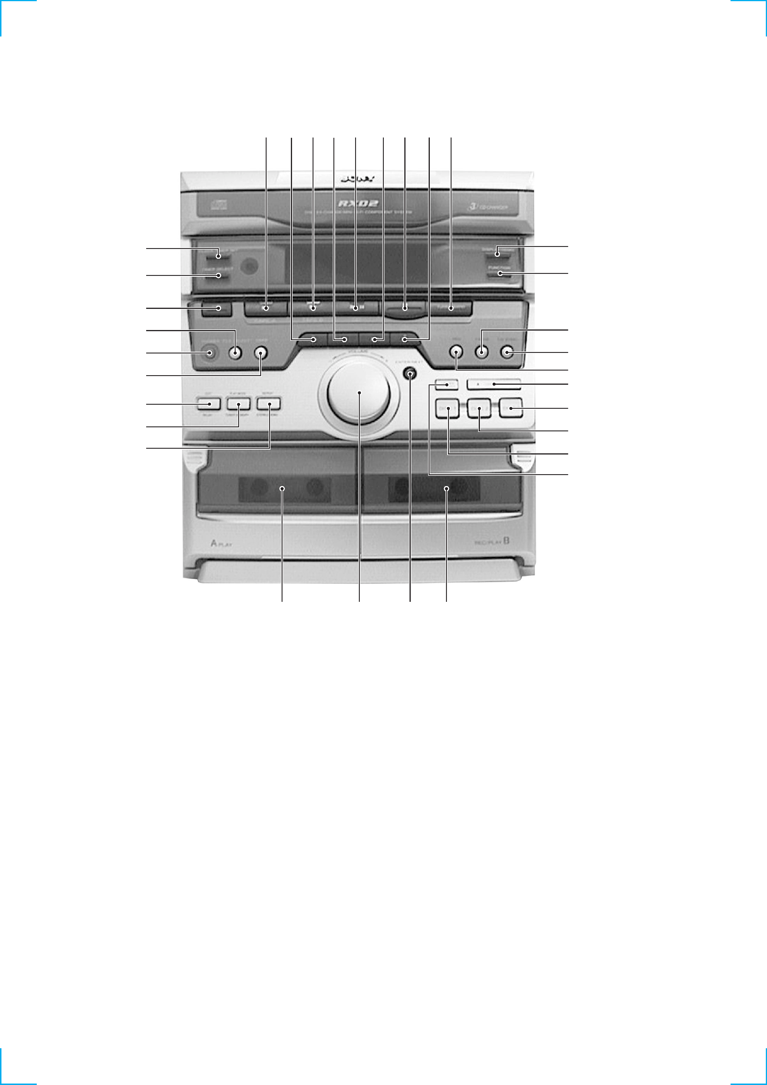
5 67 89 !º !¡ !TM
1
1/u (Power) button
2
TIMER SELECT button
3
CLOCK/TIMER button
4
TAPE A
( button and indicator
5
,
0 button
6
TAPE B
( button and indicator
7
= button
8
CD,
^ button and indicator
9
+ button
!º
p button
!¡
+,
) button
!TM
TUNER/BAND button
!£
DISPLAY/DEMO button
!¢
FUNCTION button
!
PAUSE button and indicator
!§
CD SYNC button
!¶
REC button and indicator
!·
6 OPEN/CLOSE button
!ª
DISC 3 button
@º
DISC 2 button
@¡
DISC 1 button
@TM
DISC SKIP, EX-CHANGE button
@£
Tape deck B
@¢
ENTER/NEXT button
@
VOLUME knob
@§
Tape deck A
@¶
REPEAT, STEREO/MONO button
@·
PLAY MODE, TUNER MEMORY button
@ª
EDIT, REPLAY button
#º
DBFB button
#¡
PHONES jack
#TM
FILE SELECT button
-- 5 --
SECTION 2
DISASSEMBLY
SET
CD DOOR
(Page 5)
CD MECHANISM DECK
(Page 6)
FRONT PANEL
(Page 6)
MAIN BOARD
(Page 7)
FRONT BOARD
(Page 7)
CASSETTE LID (L)/(R)
(Page 9)
CD TRAY
(Page 8)
CD DECORD BOARD
(Page 8)
BASE UNIT
(Page 9)
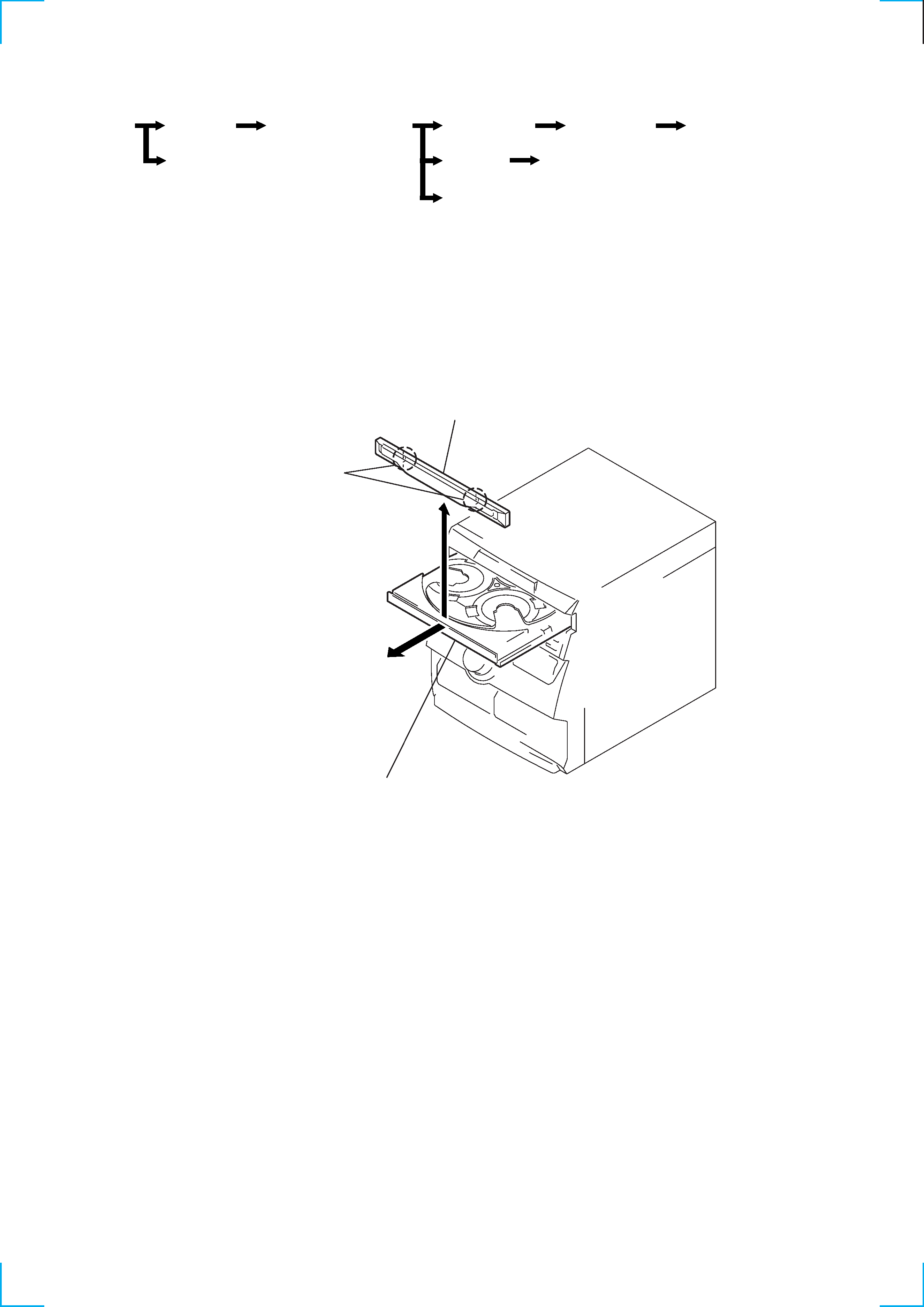
Note :
Follow the disassembly procedure in the numerical order given.
1 Pull out the CD tray and remove the CD door
with releasing claws into the direction of arrow.
2 CD door
Two claws
2-1. CD DOOR