SERVICE MANUAL
General
Power requirements
Tourist model:
110 120 V or 220 240 V
AC, 50/60 Hz
Adjustable with voltage selector
Other models:
220 V AC, 50/60 Hz
Power consumption
Tourist model:
75 watts during normal operation
240 V AC
Other models:
60 watts during normal operation
Dimensions (w/h/d) incl. projecting parts and controls
Approx. 175
× 250 × 370 mm
Mass
Approx. 7.5 kg
Design and specifications are subject to change
without notice.
MD deck section
System
MiniDisc digital audio system
Laser
Semiconductor laser (
=780 nm)
Emission duration: continuous
Laser output
Max. 44.6
µW*
* This output is the value
measured at a distance of 200 mm
from the objective lens surface on
the Optical Pick-up Block with a
7 mm aperture.
Sampling frequency
44.1 kHz
Frequency response
5 Hz 20 kHz
Tuner section
FM stereo, FM/AM superheterodyne tuner
FM tuner section
Tuning range
Tourist model:
76.0 108.0 MHz
(50 kHz step)
Other models:
87.5 108.0 MHz
(50 kHz step)
Aerial
FM lead aerial
Aerial terminals
75 ohms unbalanced
Intermediate frequency
10.7 MHz
AM tuner section
Tuning range
531 1,602 kHz
(with the interval set at 9 kHz)
530 1,710 kHz
(with the interval set at 10 kHz)
Aerial
AM loop aerial
External aerial terminals
Intermediate frequency
450 kHz
Amplifier section
Tourist model:
Continuous RMS power output (Reference):
20 + 20 watts (6 ohms at 1 kHz,
10% THD, 240 V)
Other models:
Continuous RMS power output (Reference):
20 + 20 watts (6 ohms at 1 kHz,
10% THD, 220 V)
Inputs
TAPE IN (phono jacks):
voltage 250 mV, impedance
47 kilohms
DIGITAL OPTICAL IN (Supported sampling frequencies:
32 kHz, 44.1 kHz and 48 kHz)
ANALOG IN (stereo minijack):
voltage 250 mV, impedance
47 kilohms
Outputs
TAPE OUT (phono jacks):voltage 250 mV, impedance
1 kilohm
PHONES (stereo minijack):
accepts headphones of 8 ohms or
more.
SPEAKER:
accepts impedance of 6 to 16
ohms.
CD player section
System
Compact disc and digital audio
system
Laser
Semiconductor laser (
=800 nm)
Emission duration: continuous
Laser output
Max. 44.6
µW*
* This output is the value
measured at a distance of 200 mm
from the objective lens surface on
the Optical Pick-up Block with a
7 mm aperture.
Frequency response
2 Hz 20 kHz
COMPACT DISC DECK RECEIVER
SPECIFICATIONS
HCD-PX5
E Model
Tourist Model
HCD-PX5 is the Amplifier, CD player, MD
Deck and Tuner section in CMT-PX5.
Model Name Using Similar Mechanism
HCD-MD595
MD Mechanism Type
MDM-7X2A
Optical Pick-up Name
KMS-262A/J1N
Model Name Using Similar Mechanism
NEW
CD Mechanism Type
CDM63-21BD53
Base Unit Name
BU-21BD53
Optical Pick-up Name
OP Assy (A-MAX. 2)
MD
Section
CD
Section
US and foreign patents licensed from Dolby
Laboratories.
Photo: Silver model
2
SELF-DIAGNOSIS FUNCTION
The self-diagnosis function consists of error codes for customers, which are displayed automatically when errors occur, and error codes,
which show the error history in the test mode during servicing. For details on how to view error codes for the customer, refer to the
following box in the instruction manual. For details on how to check error codes during servicing, refer to the following "Procedure for
using the Self-Diagnosis Function (Error History Display Mode)".
MD SECTION
PROCEDURE FOR USING THE SELF-DIAGNOSIS FUNCTION (ERROR HISTORY DISPLAY MODE)
Note: Perform the self-diagnosis function in the "error history display mode" in the MD test mode. The following describes the least required procedure.
Be careful not to enter other modes by mistake. If you set other modes accidentally, press the [MENU/NO] button to exit the mode.
Procedure:
1. Press the I/1 button to turn the power on.
2. Press the [FUNCTION] button to set the MD function.
3. Press three buttons of x , [MD
], Z (CD3) simultaneously to enter the MD test mode and display "[Check]".
4. Turn the [ENTER/YES] knob to display "[Service]".
5. Press the [ENTER/YES] button to display "AUTO CHECK" (C01), and turn the [ENTER/YES] knob to display "Err Display" (C02).
6. Press the [ENTER/YES] button to enter the error history mode and display "op rec tm".
7. Select the contents to be displayed or executed using the [ENTER/YES] knob.
8. Press the [CD SYNC NORM SPEED] button to light up "IT" indicator, then press the [REC MODE] button will display or execute the
contents selected.
9. Press the [REC MODE] button another time returns to step 7.
10. Press the [MENU/NO] button displays "Err Display" (C02) and release the error history mode.
11. To release the MD test mode, press the [REPEAT] button to display "Initialize" and release the MD test mode.
Self-diagnosis Display
This system has a Self-diagnosis display function
to let you know if there is a system malfunction.
The display shows a code made up of three or five
letters and a message alternately to show you the
problem. To solve the problem refer to the
following list. If any problem persists, consult
your nearest Sony dealer.
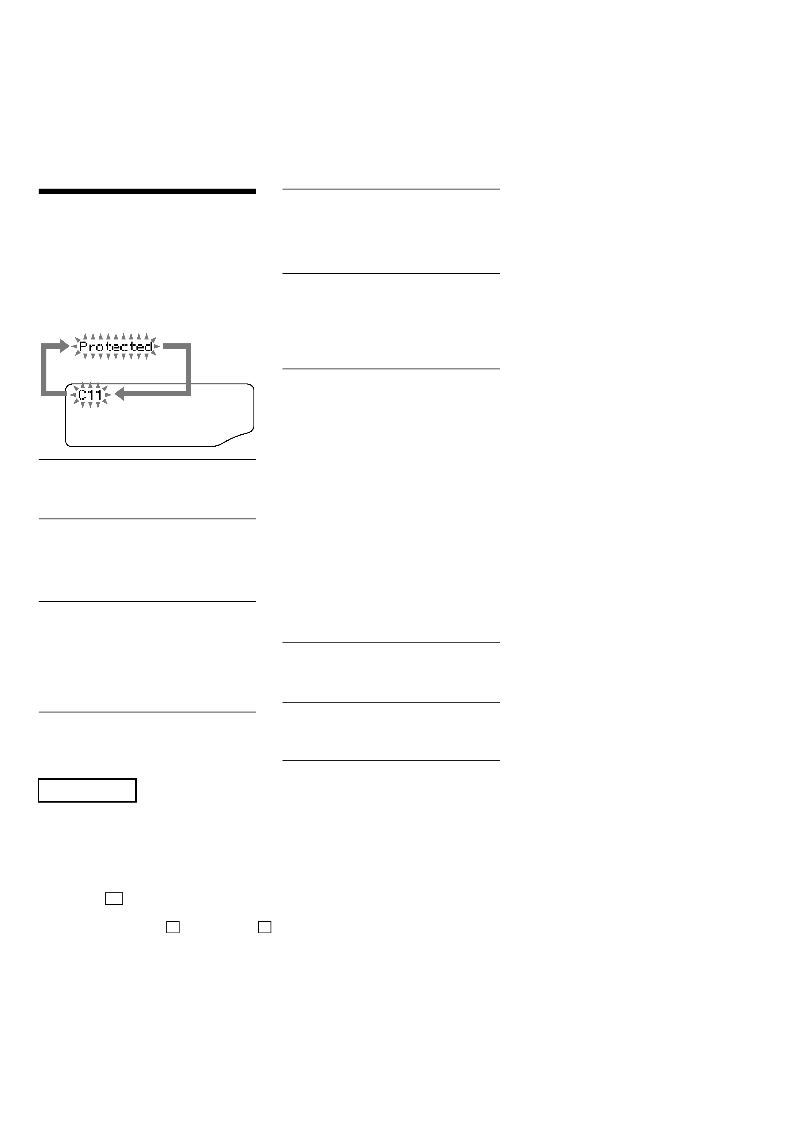
C11/Protected
The MD is protected against erasure.
cRemove the MD and slide the tab to close the
slot.
C12/Cannot Copy
You tried to record a CD or MD with a format
that the system does not support, such as a CD-
ROM.
cRemove the disc and turn off the system once,
then turn it on again.
C13/REC Error
Recording could not be performed properly.
cMove the system to a stable place, and start
recording over from the beginning.
The MD is dirty or scratched, or the MD does
not meet the standards.
cReplace the MD and start recording over from
the beginning.
C13/Read Error
The MD deck cannot read the disc information
properly.
cRemove the MD once, then insert it again.
C14/Toc Error
The MD deck cannot read the disc information
properly.
cReplace the MD.
cErase all the recorded contents of the MD
using the All Erase function.
C41/Cannot Copy
The sound source is a copy of a commercially
available music software, or you tried to record
a CD-R (Recordable CD).
cThe Serial Copy Management System
prevents making a digital copy.
You cannot record a CD-R.
C71/Check OPT-IN
This appears momentarily because of the signal
of the digital broadcast during recording.
cThere is no affect on the recorded contents.
No component is connected to the DIGITAL
OPTICAL IN jack, or a digital component is
not connected properly.
cConnect a digital component to the DIGITAL
OPTICAL IN jack properly using a digital
connecting cable (not supplied).
The connected digital component is not turned
on.
cSee the operating instructions supplied with
the connected component and confirm
whether the component is turned on.
The digital connecting cable connected to the
DIGITAL OPTICAL IN jack is pulled out, or
the connected digital component is turned off
during digital recording.
cConnect the cable, or turn on the digital
component.
E0001/MEMORY NG
There is an error in the internal data that the
system needs in order to operate.
cConsult your nearest Sony dealer.
E0101/LASER NG
There is a problem with the optical pickup.
cThe optical pickup may have failed. Consult
your nearest Sony dealer.
N X
3
ITEMS OF ERROR HISTORY MODE ITEMS AND CONTENTS
Display
Details of History
op rec tm
Cumulative recording time is displayed.
When cumulative recording time is over 1 minute, the hour and minute are displayed as they are.
When it is under 1 minute, "Under 1 min" is displayed.
The displayed time is the total time the laser is set to the high power state.
This is about 1/4 of the actual recording time. The time is displayed in decimal digits.
op play tm
Cumulative playing time is displayed.
When cumulative playing time is over 1 minute, the hour and minute are displayed as they are.
When it is under 1 minute, "Under 1 min" is displayed.
The displayed time is the total of the actual play time. Pauses are not counted.
The time is displayed in decimal digits.
spdl rp tm
Cumulative spindle motor running time is displayed.
When cumulative spindle motor run time is over 1 minute, the hour and minute are displayed as they are.
When it is under 1 minute, "Under 1 min" is displayed.
The time is displayed in decimal digits.
retry err
Displays the total number of retries during recording and number of retry errors during play.
Displayed as "r ss p ss".
"r" indicates the retries during recording while "p" indicates the retry errors during play.
The number of retries and retry errors are displayed in hexadecimal digits from 00 to FF.
total err
Displays the total number of errors.
Displayed as "total ss".
The number of errors is displayed in hexadecimal digits from 00 to FF.
err history
Displays the 10 latest errors.
Displayed as "0s ErrCd @@".
s indicates the history number. The smaller the number, the more recent is the error. (00 is the latest)
@@ indicates the error code.
Refer to the following table for the details. The error history can be switched by turning the [ENTER/YES]
knob.
retry adrs
Display the 5 latest retry address.
Display as "ss ADRS@@@@".
ss indicates the history number. The smaller the number, the more recent is the error. (00 is the latest)
@@@@ indicates the cluster of retry address.
The number of retry address can be switched by turning the [ENTER/YES] knob.
er refresh
Mode to clear the error history and retry address history.
Procedure:
1) Press the [REC MODE] button.
2) The display will change to "er refresh?", and then press the [ENTER/YES] button.
The operation is over if "Complete!" is displayed.
After this mode was executed, check the following:
· The data have been cleared.
· Perform the recording and playing to check that the mechanism operates normally.
op change
Mode to clear cumulative time of "op rec tm" and "op play tm".
These historical data are used to determine the timing when the optical pick-up is to be replaced. When the
optical pick-up was replaced, perform this operation to clear historical data.
Procedure:
1) Press the [REC MODE] button.
2) The display will change to "op change?", and then press the [ENTER/YES] button.
The operation is over if "Complete!" is displayed.
spdl change
Mode to clear cumulative time of "spdl rp tm".
This historical data is used to determine the timing when the spindle motor is to be replaced. When the spindle
motor was replaced, perform this operation to clear historical data.
Procedure:
1) Press the [REC MODE] button.
2) The display will change to "spdl change?", and then press the [ENTER/YES] button.
The operation is over if "Complete!" is displayed.
4
Error Code
Details of Error
10
Loading failed
12
Loading switch combination is illegal
20
Head of PTOC could not be read within the
specified time
21
Head of PTOC could be read but its content is
erroneous
22
Access to UTOC could not be made within the
specified time
23
UTOC could be not read within the specified
time
24
Content of UTOC is erroneous
30
Playing could not start
31
Content of sector is erroneous
40
Cause of retry occurred during normal recording
41
D-RAM overflowed and retry was executed
42
Retry was executed during the writing to TOC
43
S.F editing was interrupted by retry
50
Address could not be read except in access
processing
51
Focusing failed and it is out of control
60
Unlock retry
Table of Error Codes
5
CD SECTION
PROCEDURE FOR USING THE SELF-DIAGNOSIS
FUNCTION (ERROR HISTORY DISPLAY MODE)
1. To Enter The CD Test Mode
Procedure:
1. Press the I/1 button to turn the power on.
2. Press the [FUNCTION] button to set the CD function.
3. Press three buttons of x , [ENTER/YES], and Z (CD2)
simultaneously (When releasing the buttons, the [ENTER/YES]
button is the last to be released).
4. The set enter the CD test mode (menu) and displays "dvt ERR
CODE".
Note: If the consequence was diaplayed except "dvt ERR CODE", turn the
[ENTER/YES] knob to display "dvt ERR CODE".
2. Display of Error Number
Procedure:
1. Press the Z (CD1) button to display as bellow.
(a) Number of mechanical error.
(b) Number of no disc error that occurred after chucking.
2. Press the x button to release the CD test mode.
3. Display of Mechanical Error History
Procedure:
1. In the CD test mode menu, turn the [ENTER/YES] knob to
display "dvt ECODE MEC".
2. Press the Z (CD1) button to display as bellow.
(a) The number of mechanical error.
Latest one "00" to last ten "09"
(Turn the [ENTER/YES] knob to change the error number)
(b) FF: Mechanical error, when normal operation.
Other display: Mechanical error, between mechanical initialize.
(c) 7x: Mechanical error in the midst of select a sub tray.
9x: Mechanical error in the midst of moving a sub tray from
the stocker to the main tray.
(d), (e): Not used in servicing.
3. Press the x button to release the CD test mode.
Display
Emc=**Edc=**
(a)
(b)
Display
E**M********00
(c)
(a)
(b)
(d) (e)
4. Display of No Disc Error History
Procedure:
1. In the CD test mode menu, turn the [ENTER/YES] knob to
display "dvt ECODE BU".
2. Press the Z (CD1) button to display as bellow.
(a) The number of no disc error.
Latest one "00" to last ten "09"
(Turn the [ENTER/YES] knob to change the error number)
(b) 01: Focus error
02: GFS error
03: Set up error
04: Focus error (not used in servicing)
(c) 00:No disc error (Did not chucking retry)
02: No disc error (Chucking retry to completion)
(d) The status, when determined no disc error.
2x: During setting up
3x: During reading TOC
4x: During accessing
5x: During playback
6x: During pause
7x: During manual search (during playback)
8x: During manual search (during pause)
(e) Rotation setting of the spindle motor, when determined no disc
error.
01: normal speed
02: double speed
04: four times speed
3. Press the x button to release the CD test mode.
4. To Erase The Error History
When returning the unit to the customer after completing repairs,
perform this to erase the past error history.
Procedure:
1. In the CD test mode menu, turn the [ENTER/YES] knob to
display "dvt ECNT0 MEC". (When erase the mechanical error)
Or one more turn the [ENTER/YES] knob to display "dvt
ECNT0 BU". (When erase the no disc error)
2. Press the Z (CD1) button to erase the error history
(mechanical error or no disc error) and display as bellow.
5. To Release The CD Test Mode
Press the I/1 button to turn the power off.
Display
E**D********
(c)
(a)
(b)
(d) (e)
Display
Emc=00Edc=00