1
HCD-MD373
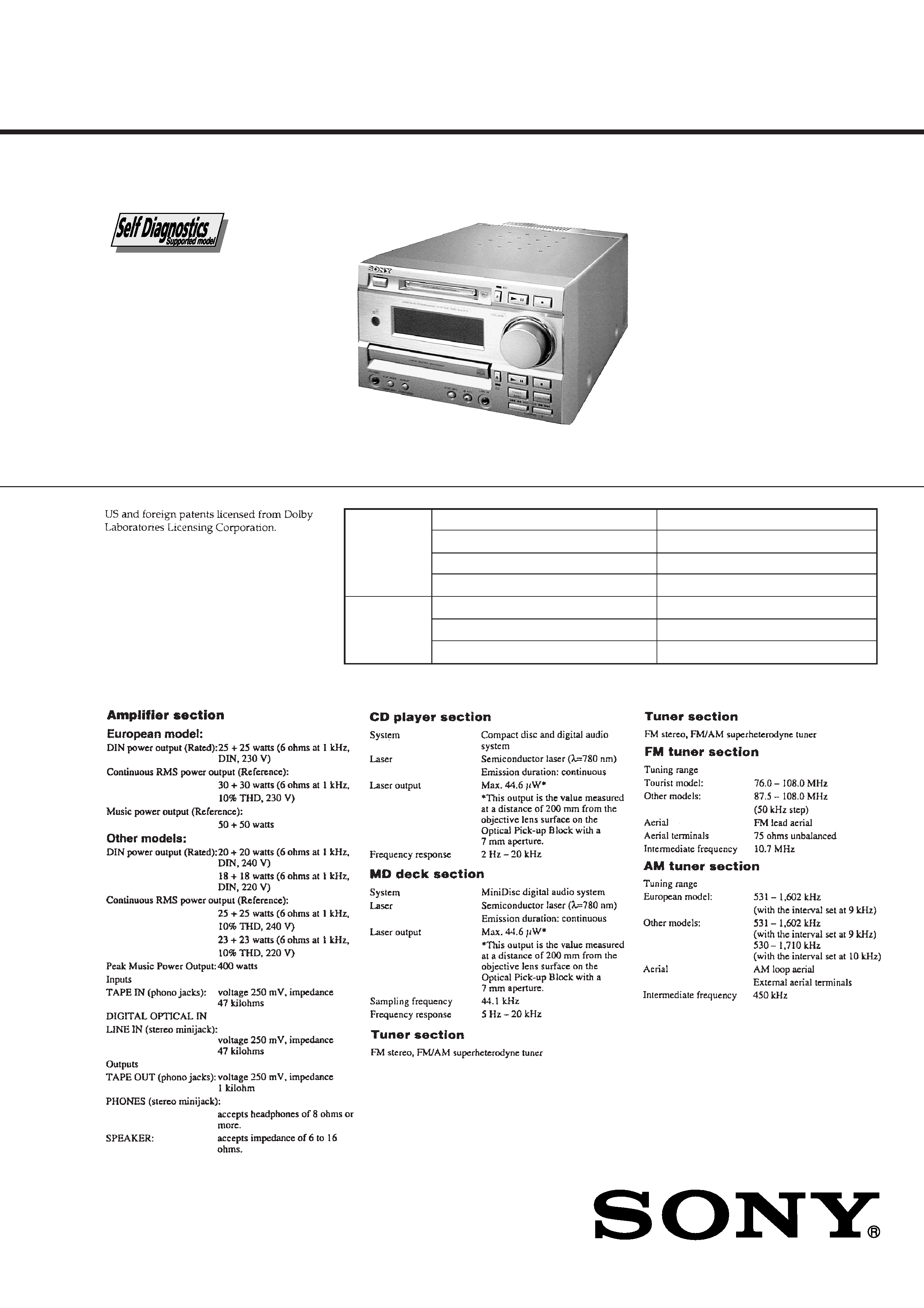
SPECIFICATIONS
SERVICE MANUAL
COMPACT DISC DECK RECEIVER
-- Continued on next page --
AEP Model
UK Model
E Model
Australian Model
Chinese Model
Tourist Model
Model Name Using Similar Mechanism NEW
Mechanism Type
CDM55A-5SBD32, CDM55C-5BD32
Base Unit Type
BU-5SBD32, BU-5BD32
Optical Pick-up Type
KSS-213BA/F-NP
Model Name Using Similar Mechanism MDS-JE520
Mechanism Type
MDM-5A
Optical Pick-up Type
KMS-260B/J1N
CD
SECTION
MD
SECTION
HCD-MD373 is the amplifir, CD, MD
and tuner section in DHC-MD373.
Ver 1.1 2001.06
9-928-998-12
2001F0200-1
© 2001.6
Sony Corporation
Home Audio Company
Shinagawa Tec Service Manual Production Group
2
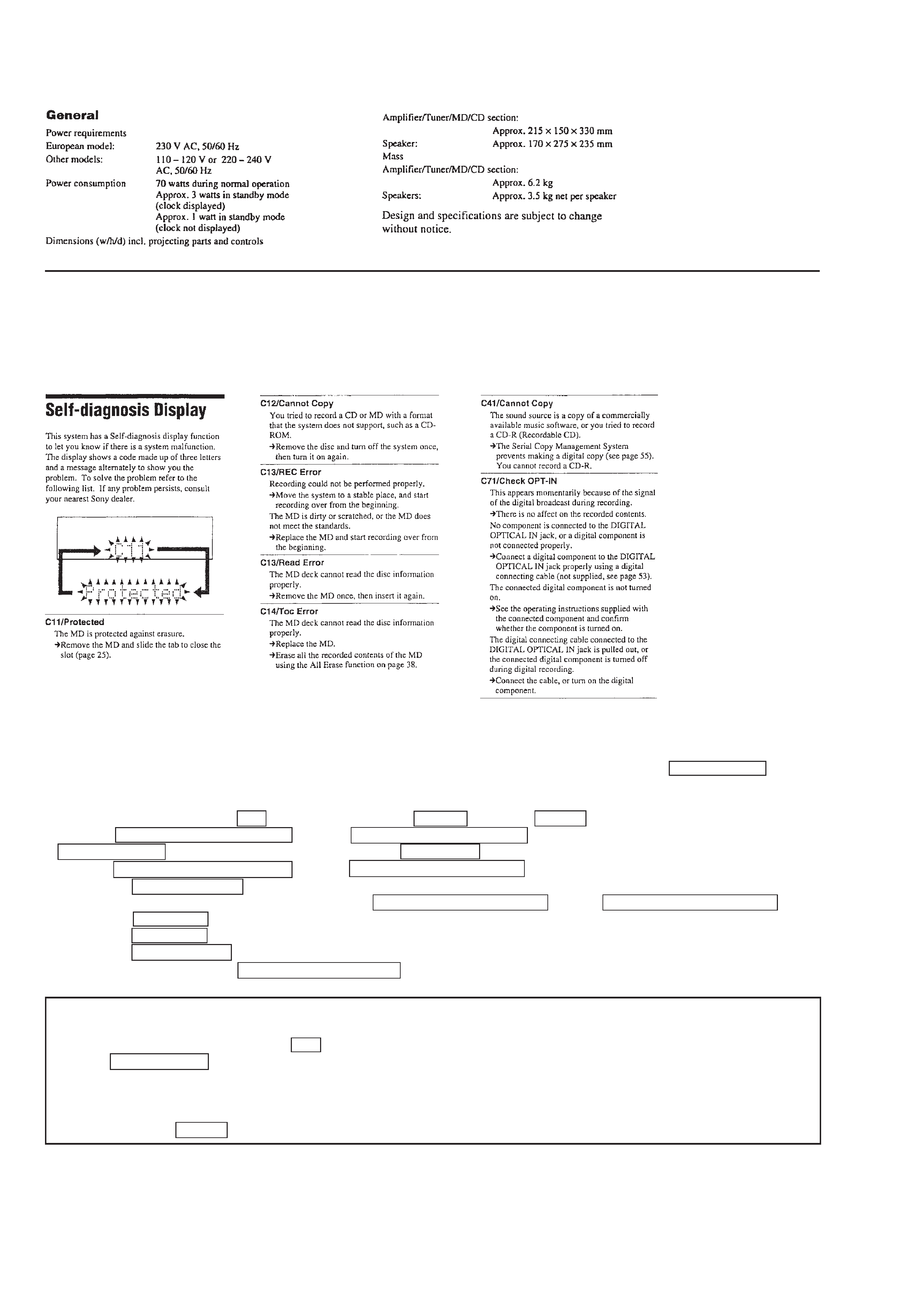
SELF-DIAGNOSIS FUNCTION
The self-diagnosis function consists of error codes for customers which are displayed automatically when errors occur, and error codes which
show the error history in the test mode during servicing. For details on how to view error codes for the customer, refer to the following box
in the instruction manual. For details on how to check error codes during servicing, refer to the following "Procedure for using the Self-
Diagnosis Function (Error History Display Mode)".
Note 1: About "R"
As this unit has only a few buttons, some operations require the use of remote commander (RM-SJ373/provided with unit: 1-418-554-11)
buttons. These operations are indicated as "R" in this manual.
Example: MENU/NO "R" ...Press the MENU/NO button of the remote commander.
Note 2:
Incorrect operations may be performed if the test mode is not set properly.
In this case, press the RESET button of the back panel.
Procedure for using the Self-Diagnosis Function (Error History Display Mode).
Note: Perform the self-diagnosis function in the "error history display mode" in the test mode. The following describes the least required
procedure. Be careful not to enter other modes by mistake. If you set other modes accidentally, press the MENU/NO "R" button to
exit the mode.
1. When the power ON, press the
1/u button while pressing the p (MD) button and r REC button together.
2. Press the
=0/MD/CD/TUNING button or )+/MD/CD/TUNING + button and when "[Service]" is displayed, press the
ENTER/YES "R" button. (If nothing is displayed, press the FUNCTION button and set the function to "MD".)
3. Press the
=0/MD/CD/TUNING button or )+/MD/CD/TUNING + button and display "ERR DP MODE".
4. Pressing the ENTER/YES "R" button sets the error history mode and displays "total rec".
5. Select the contents to be displayed or executed using the
=0/MD/CD/TUNING button or )+/MD/CD/TUNING + button.
6. Pressing the SYNC REC button will display or execute the contents selected.
7. Pressing the SYNC REC button another time returns to step 4.
8. Pressing the MENU/NO "R" button displays "ERROR DP MODE" and exits the error history mode.
9. To exit the test mode, press the REPEAT/STEREO/MONO button. The unit sets into the STANDBY state, and the test mode ends.
3
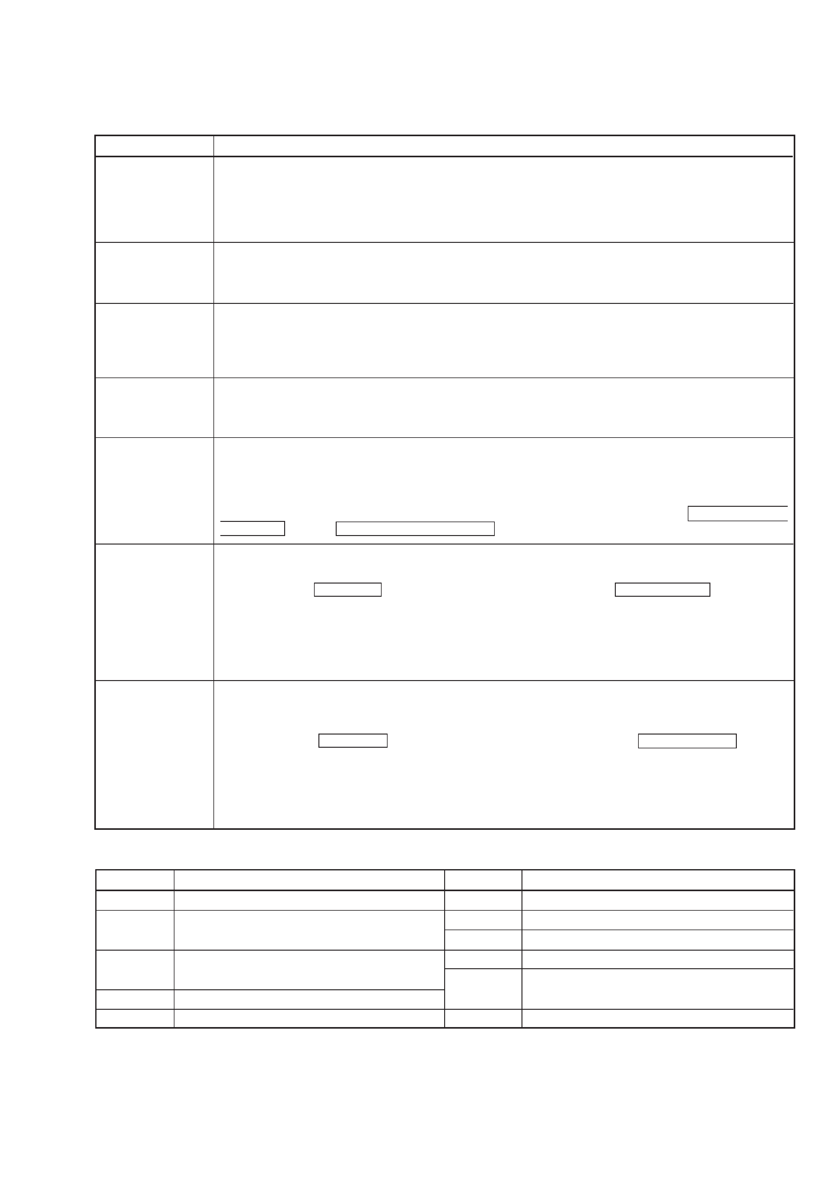
ITEMS OF ERROR HISTORY MODE ITEMS AND CONTENTS
Selecting the Test Mode
Display
total rec
total play
retry err
total err
err history
er refresh
tm refresh
Details of History
No error
Read error. PTOC cannot be read
(DISC ejected)
TOC error. UTOC error
(DISC not ejected)
Loading error
Address cannot be read (Servo has deviated)
Displays the recording time.
Displayed as "rh".
The displayed time is the total time the laser is set to the high power state.
This is about 1/4 of the actual recording time.
The time is displayed in decimal digits from 0h to 65535h.
Displays the play time.
Displayed as "ph". The time displayed is the total actual play time. Pauses are not counted.
The time is displayed in decimal digits from 0h to 65535h.
Displays the total number of retries during recording and number of retry errors during play.
Displayed as "r p".
"r" indicates the retries during recording while "p" indicates the retry errors during play.
The number of retries and retry errors are displayed in hexadecimal digits from 00 to FF.
Displays the total number of errors.
Displayed as "total ".
The number of errors is displayed in hexadecimal digits from 00 to FF.
Displays the 10 latest errors.
Displayed as "0 E@@".
indicates the history number. The smaller the number, the more recent is the error. (00 is the latest).
@@ indicates the error code.
Refer to the following table for the details. The error history can be switched by pressing the
=0/MD/CD/
TUNING button or
)+/MD/CD/TUNING + button.
Mode which erases the "retry err", "total err", and "err history" histories.
When returning the unit to the customer after completing repairs, perform this to erase the past error history,
After pressing the SYNC REC button and "er refresh?" is displayed, press the ENTER/YES "R" button to erase
the history.
"Complete!" will be displayed momentarily.
Be sure to check the following when this mode has been executed.
· The data has been erased.
· The mechanism operates normally when recording and play are performed.
Mode which erases the "total rec" and "total play" histories.
These histories serve as approximate indications of when to replace the optical pickup.
If the optical pickup has been replaced, perform this operation and erase the history.
After pressing the SYNC REC button and "tm refresh?" is displayed, press the ENTER/YES "R" button to
erase the history.
"Complete!" will be displayed momentarily.
Be sure to check the following when this mode has been executed.
· The data has been erased.
· The mechanism operates normally when recording and play are performed.
Table of Error Codes
Error Code
E00
E01
E02
E03
E04
E05
E06
E07
E08
E09
E0A
FOK has deviated
Cannot focus (Servo has deviated)
Recording retry
Recording retry error
Playback retry error
(Access error)
Play retry error (C2 error)
Details of Error
Error Code
Details of Error
4
CAUTION
Use of controls or adjustments or performance of procedures
other than those specified herein may result in hazardous ra-
diation exposure.
MODEL IDENTIFICATION
-- BACK PANEL --
SAFETY-RELATED COMPONENT WARNING !!
COMPONENTS IDENTIFIED BY MARK
! OR DOTTED LINE
WITH MARK
! ON THE SCHEMATIC DIAGRAMS AND IN
THE PARTS LIST ARE CRITICAL TO SAFE OPERATION.
REPLACE THESE COMPONENTS WITH SONY PARTS
WHOSE PART NUMBERS APPEAR AS SHOWN IN THIS
MANUAL OR IN SUPPLEMENTS PUBLISHED BY SONY.
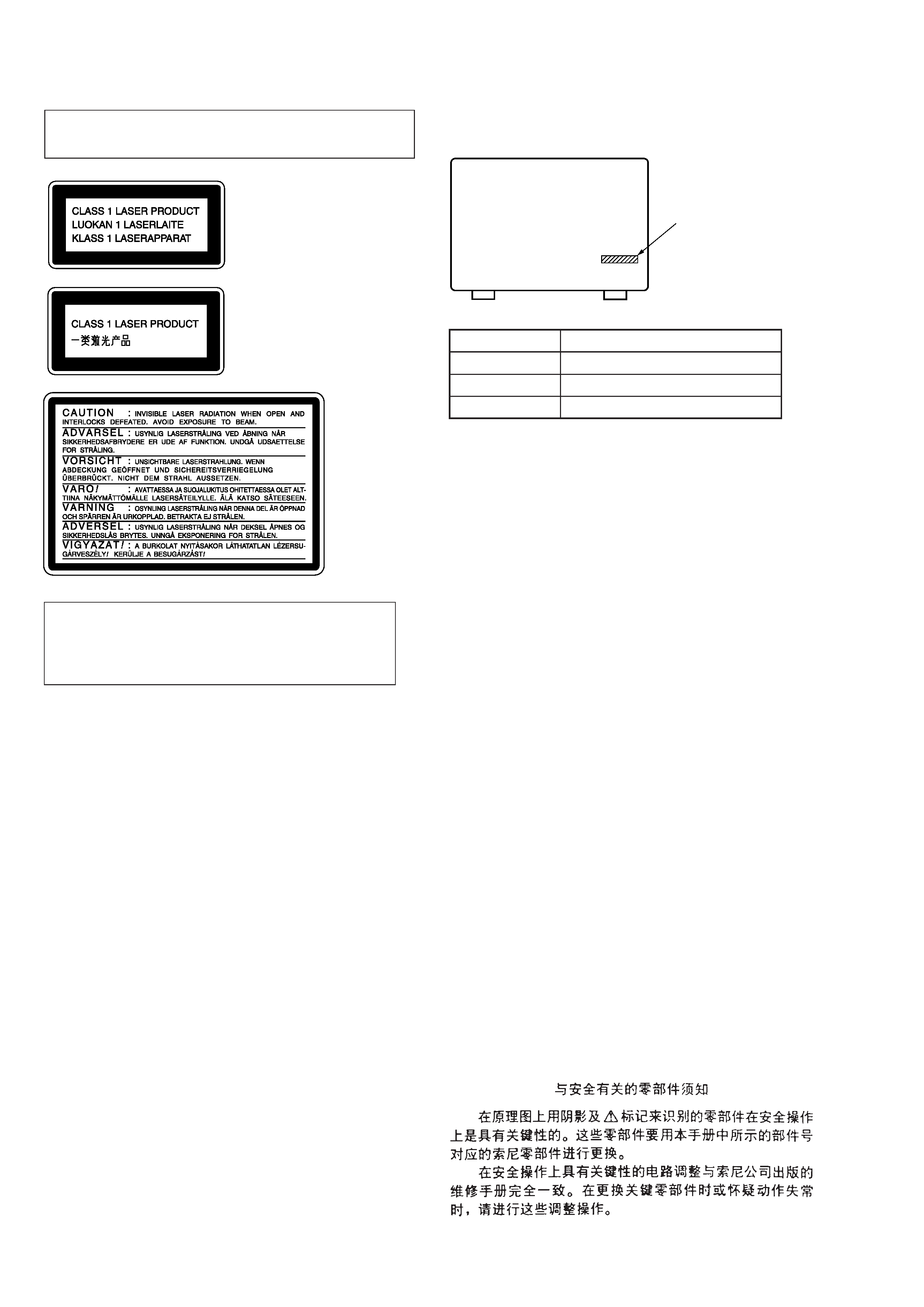
Laser component in this product is capable of emitting radiation
exceeding the limit for Class 1.
This appliance is classified as
a CLASS 1 LASER product.
The CLASS 1 LASER PROD-
UCT MARKING is located on
the rear exterior.
This caution
label is located
inside the unit.
· Abbreviation
HK
: Hong Kong model
SP
: Singapore model
MY
: Malaysia model
AR
: Argentine model
AUS : Australian model
KR
: Korea model
CH
: Chinese model
JE
: Tourist model
Parts No.
Notes on chip component replacement
· Never reuse a disconnected chip component.
· Notice that the minus side of a tantalum capacitor may be
damaged by heat.
Flexible Circuit Board Repairing
· Keep the temperature of soldering iron around 270°C
during repairing.
· Do not touch the soldering iron on the same conductor of the
circuit board (within 3 times).
· Be careful not to apply force on the conductor when soldering
or unsoldering.
PARTS No.
MODEL
4-221-082-1
AEP, UK
4-221-082-3
HK, SP, MY, AR, AUS, KR, JE
4-221-082-4
CH

5
1. SERVICING NOTE .......................................................... 6
2. GENERAL ........................................................................ 16
3. DISASSEMBLY
3-1. Case ................................................................................... 19
3-2. Front Panel ......................................................................... 20
3-3. Back Panel ......................................................................... 20
3-4. Main Board and Power Transformer ................................. 21
3-5. CD Mechanism Deck ......................................................... 21
3-6. Tray, Gear and Cam ........................................................... 22
3-7. CD Base Unit ..................................................................... 22
3-8. Optical Pick-up Section of CD (KSS-213BA/F-NP) ......... 22
3-9. BD (CD) Board, Spindle Motor (M101) and
Sled Motor (M102) ............................................................ 23
3-10. MD Mechanism Deck ........................................................ 23
3-11. Slider (Cam) ...................................................................... 24
3-12. Base Unit (MBU-5A) and BD (MD) Board ...................... 24
3-13. Over Write Head ................................................................ 25
3-14. Optical Pick-up of MD (KMS-260B/J1N) ........................ 25
3-15. Spindle Motor (M901) and SLed Motor (M902) (MD) .... 25
4. TEST MODE ..................................................................... 26
5. ELECTRICAL ADJUSTMENTS ............................... 31
6. DIAGRAMS
6-1. Circuit Boards Location ..................................................... 40
6-2. Block Diagrams
· BD (CD) Section ............................................................ 41
· BD (MD) Section (1/2) ................................................... 42
· BD (MD) Section (2/2) ................................................... 43
· Main Section ................................................................... 44
6-3. Printed Wiring Board BD (CD) Section ...................... 46
6-4. Schematic Diagram BD (CD) Section ......................... 47
6-5. Printed Wiring Board BD (MD) Section ..................... 48
6-6. Schematic Diagram BD (MD) Section (1/2) ............... 49
6-7. Schematic Diagram BD (MD) Section (2/2) ............... 50
6-8. Schematic Diagram SP Section ................................... 51
6-9. Printed Wiring Board SP Section ................................ 51
6-10. Printed Wiring Board Main Section ............................ 52
6-11. Schematic Diagram Main Section (1/3) ...................... 53
6-12. Schematic Diagram Main Section (2/3) ...................... 54
6-13. Schematic Diagram Main Section (3/3) ...................... 55
6-14. Schematic Diagram MD Digital Section ..................... 56
6-15. Printed Wiring Board MD Digital Section .................. 57
6-16. Schematic Diagram AMP Section ............................... 58
6-17. Printed Wiring Board AMP Section ............................ 59
6-18. Schematic Diagram Panel Section ............................... 60
6-19. Printed Wiring Board Panel Section ............................ 61
6-20. Schematic Diagram Power Section ............................. 62
6-21. Printed Wiring Board Power Section ........................... 63
6-22. Schematic Diagram BD Switch Section ...................... 64
6-23. Printed Wiring Board BD Swtich Section ................... 64
6-24. Schematic Diagram Loading Section .......................... 64
6-25. Printed Wiring Board Loading Section ........................ 64
6-26. IC Block Diagrams ............................................................ 65
6-27. IC Pin Functions ................................................................ 69
TABLE OF CONTENTS
7. EXPLODED VIEWS
7-1. Case and Front Panel Section ............................................ 77
7-2. Chassis Section .................................................................. 78
7-3. MD Mechanism Section (MDM-5A) ................................ 79
7-4. MD Base Unit Section (MBU-5A) .................................... 80
7-5. CD Mechanism Section (CDM55A-5SBD32)................... 81
7-6. CD Base Unit Section (BU-5SBD32) ............................... 82
7-7. CD Mechanism Section (CDM55C-5BD32) ..................... 83
7-8. CD Base Unit Section (BU-5BD32) .................................. 84
8. ELECTRICAL PARTS LIST ........................................ 85
Ver 1.1 2001.06