SERVICE MANUAL
CD
Model Name Using Similar Mechanism
HCD-MD333
Section
Base Unit Name
BU-22BD19
Optical Pick-up Name
KSS-213B/K-N
MD
Model Name Using Similar Mechanism
HCD-MD333
Section
Mechanism Name
MDM-3J
Optical Pick-up Name
KMS-260A/J1N
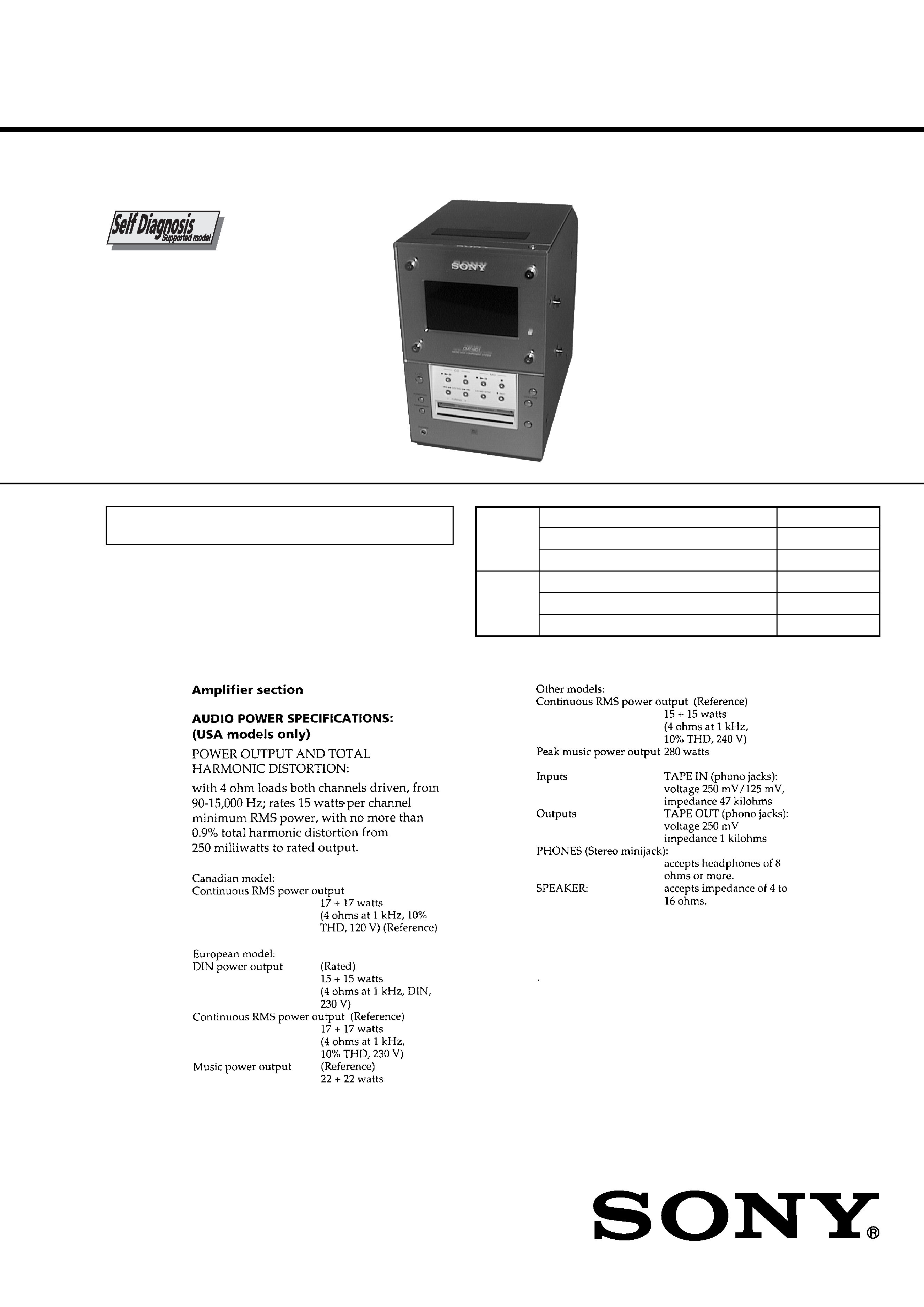
COMPACT Hi-Fi COMPONENT SYSTEM
US Model
Canadian Model
AEP Model
UK Model
E Model
SPECIFICATIONS
HCD-MD1EX
HCD-MD1EX is the Amplifier, CD player,
Mini disc Deck and Tuner section in
CMT-MD1.
Continued on next page
U.S. and foreign patents licensed form Dolby Laboratories
Licensing Corporation.
Ver 1.2 2003.06
9-922-950-13
Sony Corporation
2003F05-1
Home Audio Company
C
2003.06
Published by Sony Engineering Corporation
2
3
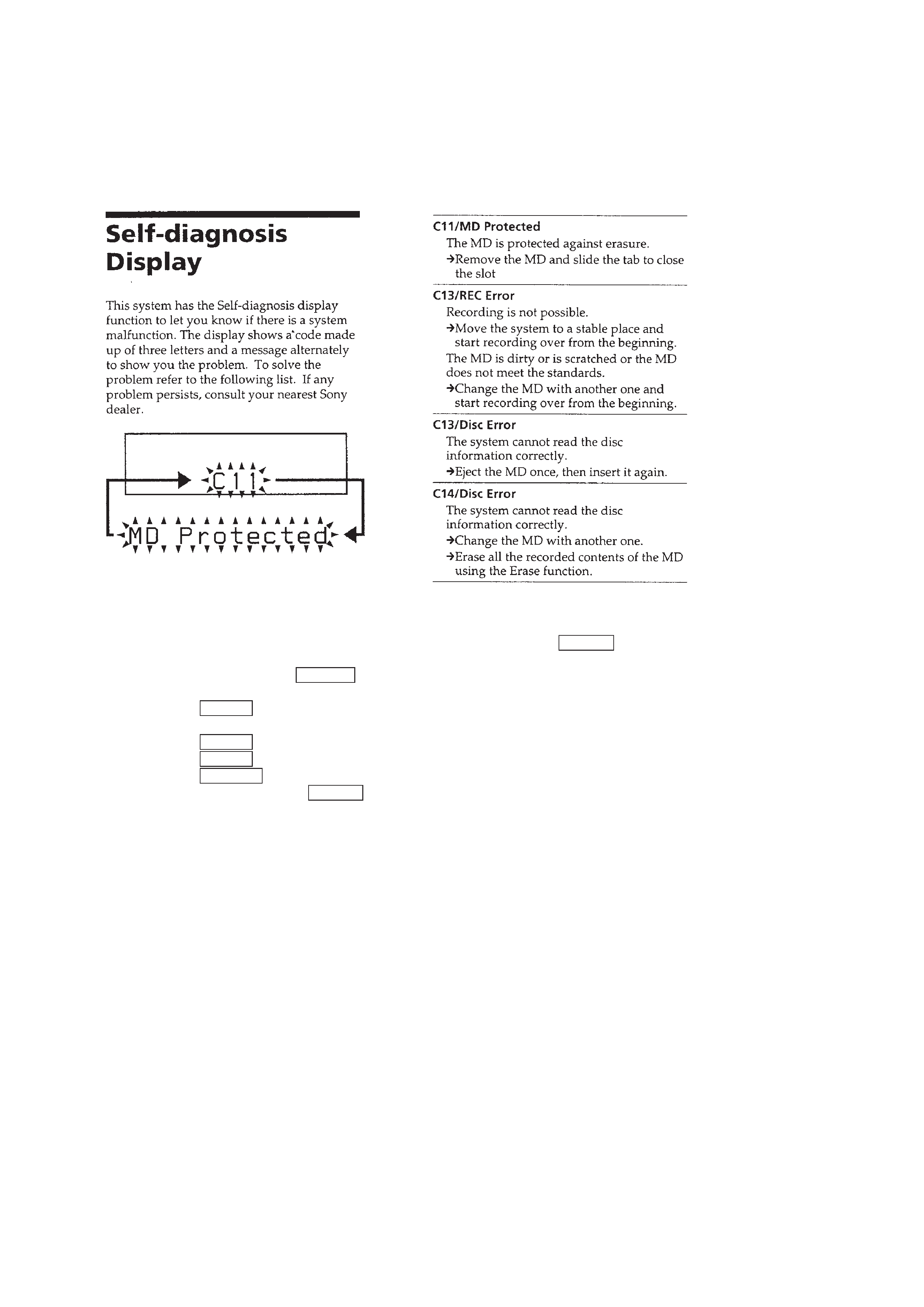
SELF-DIAGNOSIS FUNCTION
The self-diagnosis function consists of error codes for users which are displayed automatically when errors occur, and error codes which
show the error history in the test mode during servicing. For details on how to view error codes for users, refer to the following box in the
instruction manual. For details on how to perform checks during servicing, refer to the following "Procedure for Using the Self-Diagnosis
Function (Error History Display Mode)".
Procedure for Using the Self-Diagnosis Function (Error History Display Mode)
Note: Perform the self-diagnosis function in the "error history display mode" in the test mode. The following describes the least required steps. Be careful
not to enter other modes by mistake. If other modes are set accidentally, press the
^ (CD) button to exit that mode.
1. With the power off, press the
=0 button while pressing the [VOLUME] button.
2. Press the [VOLUME+/] button to display "ERR DP MODE".
3. Pressing the
p (CD) button sets the error history mode and displays "total rec".
4. Select the contents to be displayed or executed with pressing the [VOLUME+/] button.
5. Pressing the
6 (CD) button displays or executes the contents selected.
6. Pressing the
6 (CD) button another time returns to step 4.
7. Pressing the
^ (CD) button displays "ERR DP MODE" and exits the error history mode.
8. To exit the test mode, press the
p (MD) button while pressing the [FUNCTION] button.
The unit sets into the STANDBY state, and the test mode ends.
4
Displays the recording time in the form of "rh".
The displayed time is the total number of hours the laser is high power, which is about one-fourth of the actual
recording time. The time is displayed in decimal digits between 0h to 65535h.
Displays the playback time in the form of "ph".
The displayed time is the total actual play time. The paused time is not counted. The time is displayed in
decimal digits between 0h to 65535h.
Displays the total number of retries during recording and retry errors during playback in the form of "rp".
"r" indicates the retries during recording while "p" indicates the retry errors during playback. The number of
retries is displayed in hexadecimal digits between 00 to FF.
Displays the total number of errors in the form of "total ".
The number of errors is displayed in hexadecimal digits between 00 to FF.
Displays the 10 latest errors in the form of "0 E@@".
The indicates the history number. The smaller the number, the newer is the error. (00 is the latest error.)
The @@ indicates the error code. Refer to the following table for details. Press the [VOLUME+/] button to
switch the error history.
Mode which erases all the error histories.
The error history serves as a reference for when to replace the optical pick-up. Perform this procedure when the
optical pick-up has been replaced in order to erase past error histories and not at other times. Press the
p (CD)
button when "er refresh??" is displayed. The history will be erased and "Complete!" will be displayed momen-
tarily. Be sure to check the following when this mode has been executed.
· Check that the data has been erased.
· Perform recording and playback, and check that the mechanism operates normally.
ITEM OF ERROR HISTORY MODE ITEMS AND CONTENTS
Selecting the Test Mode
Display
total rec
total play
retry err
total err
err history
er refresh?
Details of History
No error
Disc error. Cannot read PTOC
(Disc is ejected out)
Disc error. UTOC error
(Disc is not ejected out)
Loading error
Cannot read address (Servo has deviated)
Table of Error Codes
Error Code
E00
E01
E02
E03
E04
E05
E06
E07
E08
E09
E0A
FOK has deviated
Unfocused (Servo has deviated)
Recording retry
Recording retry error
Play retry error
(Access error)
Playback retry error (C2 error)
Details of Error
Error Code
Details of Error

5
TABLE OF CONTENTS
SELF-DIAGNOSIS FUNCTION ................................... 3
1.
SERVICING NOTES .............................................. 6
2.
GENERAL .................................................................. 9
3.
DISASSEMBLY ......................................................... 12
4.
SERVICE MODE ...................................................... 19
5.
TEST MODE .............................................................. 20
6.
ELECTRICAL ADJUSTMENTS
MD Section ..................................................................... 26
CD Section ...................................................................... 31
7.
DIAGRAMS
7-1. Block Diagram CD Section ..................................... 33
7-2. Block Diagram MD Section .................................... 35
7-3. Block Diagram MAIN Section ................................ 37
7-4. Block Diagram
DISPLAY/POWER SUPPLY Section ..................... 39
7-5
Note for Printed Wiring Boards and
Schematic Diagrams ....................................................... 42
7-6. Printed Wiring Board BD (CD) Section .................. 43
7-7. Schematic Diagram BD (CD) Section ...................... 45
7-8. Printed Wiring Board BD (MD) Section ................. 47
7-9. Schematic Diagram BD (MD) Section (1/3) ............ 49
7-10. Schematic Diagram BD (MD) Section (2/3) ............ 51
7-11. Schematic Diagram BD (MD) Section (3/3) ............ 53
7-12. Printed Wiring Board MAIN Board (side A) .......... 55
7-13. Printed Wiring Board MAIN Board (side B) .......... 57
7-14. Schematic Diagram MAIN Section (1/2) ................ 59
7-15. Schematic Diagram MAIN Section (2/2) ................ 61
7-16. Printed Wiring Boards PANEL Section .................. 63
7-17. Schematic Diagram PANEL Section ........................ 65
7-18. Printed Wiring Boards
AMP/TRANSFORMER Section .............................. 67
7-19. Schematic Diagram
AMP/TRANSFORMER Section .............................. 69
7-20. Printed Wiring Board POWER Section ................... 71
7-21. Schematic Diagram POWER Section ...................... 73
7-22. Printed Wiring Boards MOTOR/SW Section ......... 75
7-23. Schematic Diagram MOTOR/SW Section ............... 76
7-24. IC Pin Function Description ........................................... 86
8.
EXPLODED VIEWS ................................................ 96
9.
ELECTRICAL PARTS LIST ............................. 103