-- 1 --
HCD-GR3/RX30
SERVICE MANUAL
US Model
Canadian Model
AEP Model
UK Model
HCD-RX30
E Model
Australian Model
HCD-GR3
COMPACT DISC DECK RECEIVER
MICROFILM
-- Continued on next page --
Model Name Using Similar Mechanism
HCD-H991AV
CD Mechanism Type
CDM38-5BD19FK
Base Unit Type
BU-5BD19
Optical Pick-up Type
KSS-213B/K-N
Model Name Using Similar Mechanism
HCD-D270/G3100/N255
Tape Transport Mechanism Type
TCM-YSW47C24
CD
SECTION
TAPE
DECK
SECTION
SPECIFICATIONS
AEP, UK, East European models:
MW:
531 1,602 kHz (with the
interval set at 9 kHz)
LW:
153 279 kHz (with the
interval set at 3 kHz)
Other models:
AM:
531 1,602 kHz (with the
tuning interval set at 9 kHz)
530 1,710 kHz (with the
tuning interval set at 10 kHz)
Antenna
AM loop antenna,
External antenna terminals
Intermediate frequency
450 kHz
Amplifier section
US, Canadian models:
Continuous RMS power output
60W+60W (6 ohms at
1 kHz, 5% THD)
Dolby noise reduction manufactured under license
from Dolby Laboratories Licensing Corporation.
"DOLBY" and the double-D symbol
a are trade-
marks of Dolby Laboratories Licensing Corporation.
* Manufactured under license from Dolby Laborato-
ries Licensing Corporation. "Dolby", the double-D
symbol
a are "Pro Logic" are trademarks of Dolby
Laboratories Licensing Corporation.
Photo: HCD-RX30
HCD-GR3/RX30 is the tuner, deck, CD and ampli-
fier section in MHC-GR3/RX30.
Wavelength
780 790 nm
Tuner section
FM stereo, FM/AM superheterodyne
tuner
FM tuner section
Tuning range
87.5 108.0 MHz
Antenna
FM lead antenna
Antenna terminals
75 ohm unbalanced
Intermediate frequency
10.7 MHz
AM tuner section
Tuning range
US, Canadian models:
AM:
531 1,710 kHz (with the
tuning interval set at 9 kHz)
530 1,710 kHz
(with the tuning interval set
at 10 kHz)
German models:
AM:
531 1,602 kHz (with the
interval set at 9 kHz)
CD player section
System
Compact disc and digital
audio system
Laser
Semiconductor laser
Laser output
Max. 44.6µ W*
* This output is the value
measured at a distance of
200 mm from the
objective lens surface on
the Optical Pick-up Block
with 7 mm aperture.
-- 2 --
SUPER WOOFER:
Voltage 1V, impedance
1 kilo ohms.
Tape player section
Recording system
4-track 2-channel stereo
Frequency response
(DOLBY NR OFF)
40 13,000 Hz (±3 dB),
using Sony TYPE I cassette
40 14,000 Hz (±3 dB),
using Sony TYPE II cassette
Wow and flutter
±0.15% W. Peak (IEC)
0.1% W. RMS (NAB)
±0.2% W. Peak (DIN)
General
Power requirements
US, Canadian, Mexican models:
120V AC, 60 Hz
AEP, UK, German, East European models:
220 230V AC, 50/60 Hz
South Africa model:
220 240V AC, 50/60 Hz
Australian model:
240V AC, 50/60 Hz
Other models:
110 120V or 220 240V
AC, 50/60 Hz
Adjustable with the voltage
selector
Power consumption
US model: 105W
Canadian model: 115 W
Other models: 95W
Dimensions
Approx. 280 x 330 x 360 mm
(11 1/8 x 13 x 14 1/4 in)
(w/h/d) incl.
projecting parts and controls
Mass
Approx. 7 kg (15 lb 7 oz)
Design and specifications are subject to change
without notice.
CAUTION
Use of controls or adjustments or performance of procedures
other than those specified herein may result in hazardous ra-
diation exposure.
Notes on chip component replacement
· Never reuse a disconnected chip component.
· Notice that the minus side of a tantalum capacitor may be
damaged by heat.
Flexible Circuit Board Repairing
· Keep the temperature of soldering iron around 270°C
during repairing.
· Do not touch the soldering iron on the same conductor of the
circuit board (within 3 times).
· Be careful not to apply force on the conductor when soldering
or unsoldering.
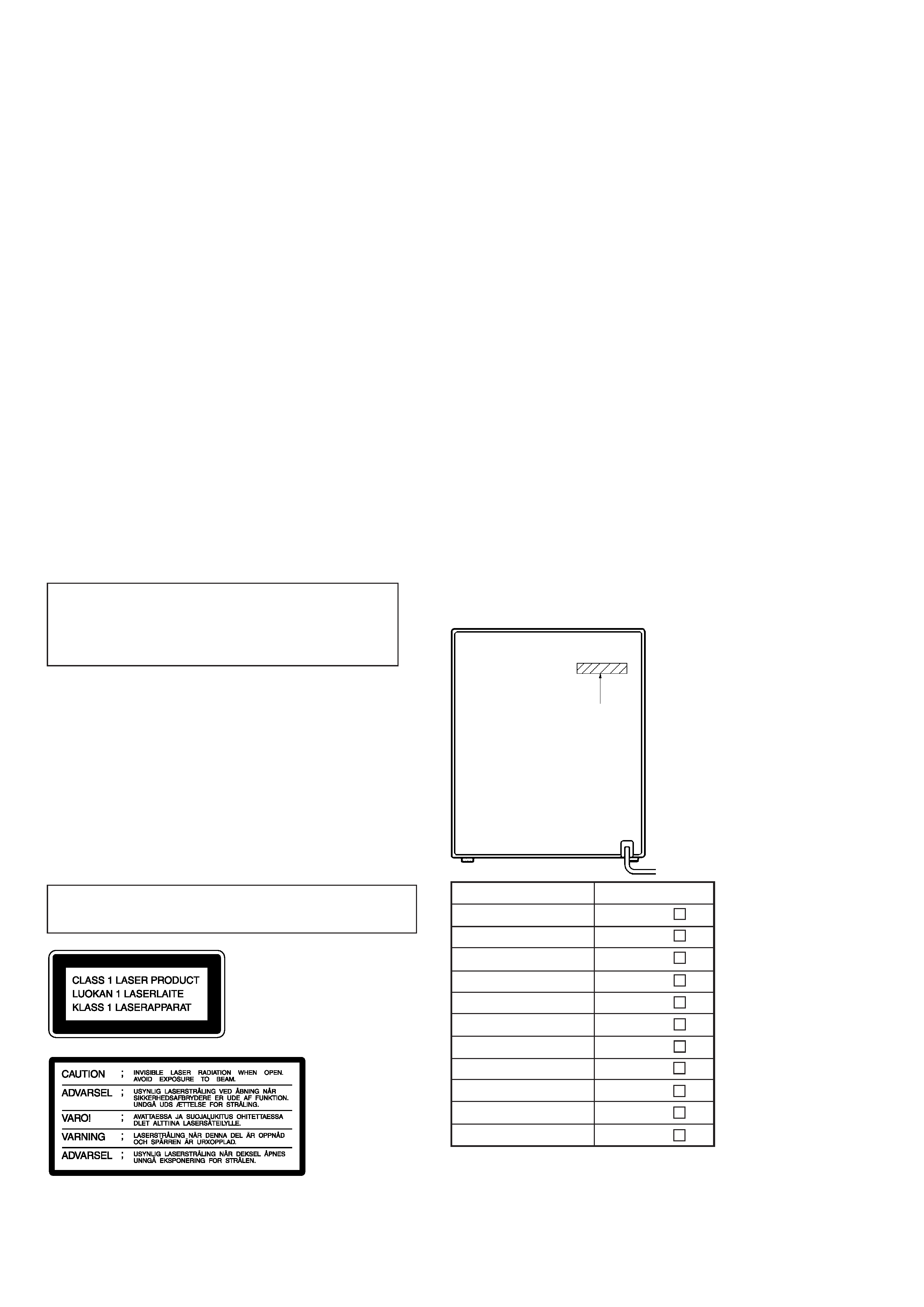
Laser component in this product is capable of emitting radiation
exceeding the limit for Class 1.
This appliance is classified as
a CLASS 1 LASER product.
The CLASS 1 LASER PROD-
UCT MARKING is located on
the rear exterior.
This caution
label is located
inside the unit.
MODEL IDENTIFICATION
-- BACK PANEL --
Parts No.
· Abbreviation
CND : Canadian model
G
: German model
AUS : Australian model
AR
: Argentine model
SAF : South African model
MX
: Mexican model
EE
: East European model
GR3 : E model
GR3 : AUS model
GR3 : MX model
GR3 : AR model
GR3 : SAF model
RX30 : US model
RX30 : CND model
RX30 : AEP model
RX30 : G model
RX30 : UK model
RX30 : EE model
MODEL
PARTS No.
4-988-804-0
4-988-804-1
4-988-804-2
4-988-804-3
4-988-804-4
4-988-810-0
4-988-810-1
4-988-811-0
4-988-811-1
4-988-811-2
4-988-811-3
AEP, UK, German, East European models:
DIN power output
40W+40W (6 ohms at
1 kHz, DIN)
Continuous RMS power output
50W+50W (6 ohms at
1 kHz, 10% THD)
Music power output
85W+85W (6 ohms at
1 kHz, 10% THD)
Other models:
Peak music power output
800W
Continuous RMS power output
50W+50W (6 ohms at
1 kHz, 10% THD)
Inputs
VIDEO (phono jacks):
voltage 250 mV,
impedance 47 kilohms
Outputs
PHONES (stereo phone jack):
accepts headphones of
8 ohms or more.
SPEAKER: accepts impedance of 6 to
16 ohms.
-- 3 --
SAFETY-RELATED COMPONENT WARNING !!
COMPONENTS IDENTIFIED BY MARK
! OR DOTTED LINE
WITH MARK
! ON THE SCHEMATIC DIAGRAMS AND IN
THE PARTS LIST ARE CRITICAL TO SAFE OPERATION.
REPLACE THESE COMPONENTS WITH SONY PARTS
WHOSE PART NUMBERS APPEAR AS SHOWN IN THIS
MANUAL OR IN SUPPLEMENTS PUBLISHED BY SONY.
ATTENTION AU COMPOSANT AYANT RAPPORT
À LA SÉCURITÉ!!
LES COMPOSANTS IDENTIFIÉS PAR UNE MARQUE
!SUR
LES DIAGRAMMES SCHÉMATIQUES ET LA LISTE DES
PIÈCES SONT CRITIQUES POUR LA SÉCURITÉ DE
FONCTIONNEMENT. NE REMPLACER CES COMPOSANTS
QUE PAR DES PIÈCES SONY DONT LES NUMÉROS
SONT DONNÉS DANS CE MANUEL OU DANS LES
SUPPLÉMENTS PUBLIÉS PAR SONY.
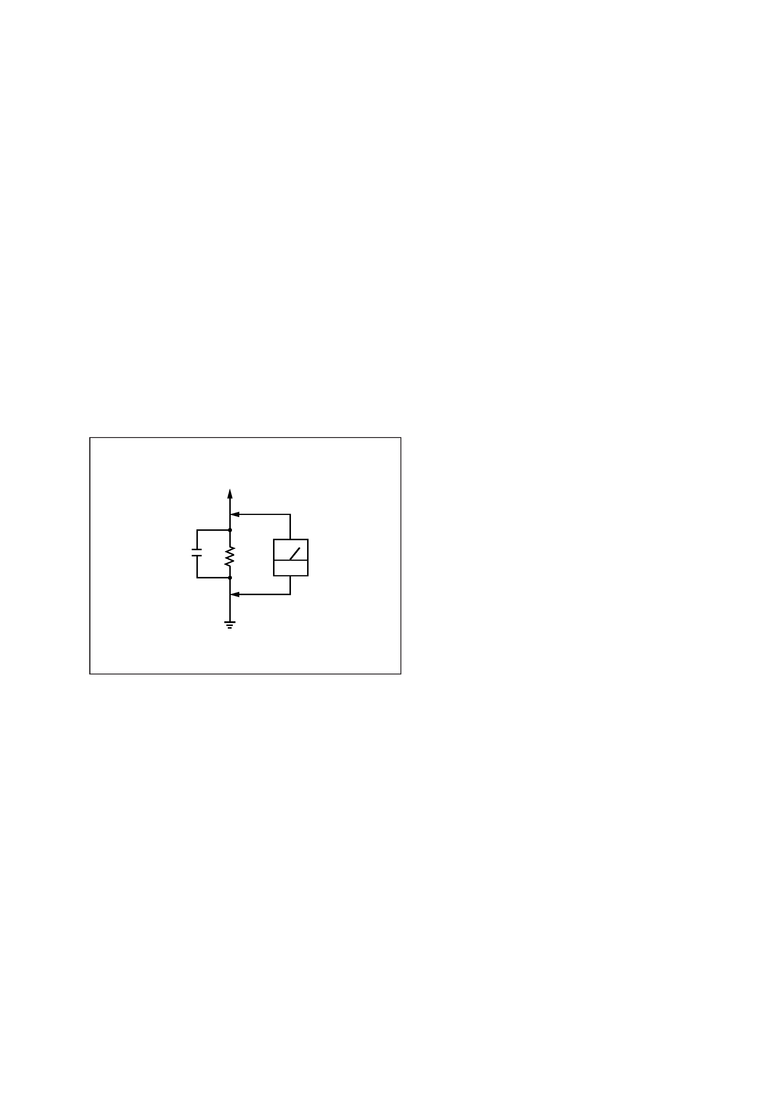
To Exposed Metal
Parts on Set
0.15µF
1.5k
AC
voltmeter
(0.75V)
Earth Ground
SAFETY CHECK-OUT
After correcting the original service problem, perform the follow-
ing safety checks before releasing the set to the customer:
Check the antenna terminals, metal trim, "metallized" knobs, screws,
and all other exposed metal parts for AC leakage. Check leakage as
described below.
LEAKAGE
The AC leakage from any exposed metal part to earth Ground and
from all exposed metal parts to any exposed metal part having a
return to chassis, must not exceed 0.5 mA (500 microampers). Leak-
age current can be measured by any one of three methods.
1. A commercial leakage tester, such as the Simpson 229 or RCA
WT-540A. Follow the manufacturers' instructions to use these
instruments.
2. A battery-operated AC milliammeter. The Data Precision 245
digital multimeter is suitable for this job.
3. Measuring the voltage drop across a resistor by means of a VOM
or battery-operated AC voltmeter. The "limit" indication is 0.75
V, so analog meters must have an accurate low-voltage scale.
The Simpson 250 and Sanwa SH-63Trd are examples of a pas-
sive VOM that is suitable. Nearly all battery operated digital
multimeters that have a 2V AC range are suitable. (See Fig. A)
Fig. A. Using an AC voltmeter to check AC leakage.
TABLE OF CONTENTS
1. SERVICING NOTE .......................................................... 4
2. GENERAL .......................................................................... 5
3. DISASSEMBLY
3-1. Loading Panel ....................................................................... 7
3-2. Front Panel ........................................................................... 7
3-3. TC Mechanism Deck ............................................................ 8
3-4. CD SW Board , Panel Board ................................................. 8
3-5. Disc Tray ............................................................................. 9
4. MECHANICAL ADJUSTMENTS .......................... 10
5. ELECTRICAL ADJUSTMENTS ............................... 10
6. DIAGRAMS
6-1. Circuit Boards Location ...................................................... 16
6-2. Brock Diagrams
· Tuner Section ................................................................... 17
· Deck Section .................................................................... 19
· CD Section ....................................................................... 21
· Main Section .................................................................... 23
6-3. Printed Wiring Board --Tuner Section -- .......................... 25
6-4. Schematic Diagram -- Tuner Section -- ............................ 26
6-5. Printed Wiring Board -- Main Section -- .......................... 28
6-6. Schematic Diagram -- Main Section -- ............................ 31
6-7. Schematic Diagram -- Deck Section -- ............................ 36
6-8. Printed Wiring Board -- CD Motor Section -- .................. 39
6-9. Schematic Diagram -- CD Motor Section -- .................... 40
6-10. Schematic Diagram -- CD Section -- ............................. 42
6-11. Printed Wiring Board -- CD Section -- .......................... 45
6-12. Printed Wiring Board -- Panel Section -- ....................... 47
6-13. Schematic Diagram -- Panel Section -- ......................... 49
6-14. IC Pin Functions ............................................................... 51
6-15. IC Block Diagrams ........................................................... 55
7. EXPLODED VIEWS
7-1. Case Section ........................................................................ 59
7-2. Front Panel Section 1 .......................................................... 60
7-3. Front Panel Section 2 .......................................................... 61
7-4. Back Panel Section ............................................................. 62
7-5. CD Mechanism Section 1 (CDM38-5BD19) ...................... 63
7-6. CD Mechanism Section 2 (CDM38-5BD19) ...................... 64
7-7. Base Unit Section (BU-5BD19) .......................................... 65
7-8. TC Mechanism Section 1 (TCM-YSW47C24) ................... 66
7-9. TC Mechanism Section 2 (TCM-YSW47C24) ................... 67
7-10. TC Mechanism Section 3 (TCM-YSW47C24) ................ 68
8. ELECTRICAL PARTS LIST ........................................ 69
-- 4 --
SECTION 1
SERVICING NOTE
NOTES ON HANDLING THE OPTICAL PICK-UP BLOCK
OR BASE UNIT
The laser diode in the optical pick-up block may suffer electrostatic
break-down because of the potential difference generated by the
charged electrostatic load, etc. on clothing and the human body.
During repair, pay attention to electrostatic break-down and also
use the procedure in the printed matter which is included in the
repair parts.
The flexible board is easily damaged and should be handled with
care.
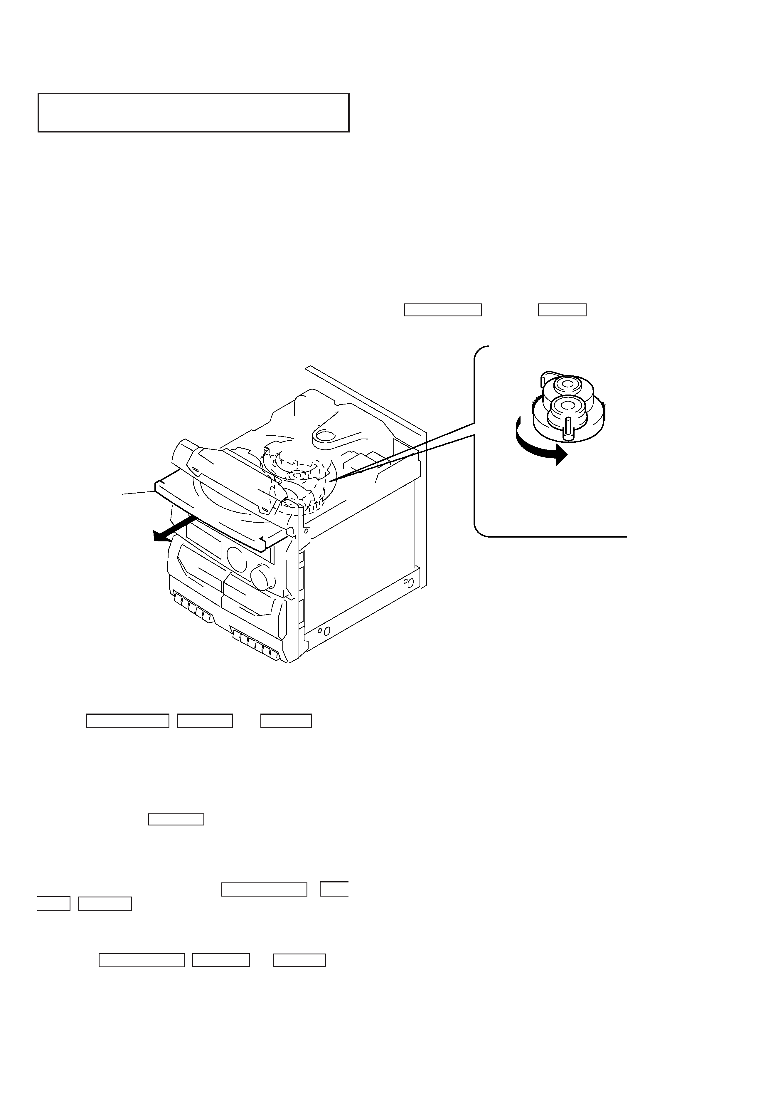
HOW TO OPEN THE DISC TRAY WHEN POWER SWITCH
TURNS OFF
NOTES ON LASER DIODE EMISSION CHECK
The laser beam on this model is concentrated so as to be focused on
the disc reflective surface by the objective lens in the optical pick-
up block. Therefore, when checking the laser diode emission, ob-
serve from more than 30 cm away from the objective lens.
LASER DIODE AND FOCUS SEARCH OPERATION
CHECK
Carry out the "S curve check" in "CD section adjustment" and check
that the S curve waveform is output three times.
Switching the channel step 9 KHz/10 KHz
Press ENTER/NEXT button and POWER button simultaneously
to switch the AM channel step 9 KHz and 10 KHz. Be sure not to
change with carelessness.
FL Display Tube, LED All Lit and Key Check mode
When the TUNER/BAND , DISPLAY , and MENU 2 buttons
are pressed simultaneously, the FL display tube and LEDs will all
light up. Press any button to enter the key check mode.
When the key check mode is entered, the FL display tube displays
"KEY 1 0 0". Each time a button is pressed, the counter increases
in the following order, KEY 2
n KEY 3 n KEY 4.
If buttons already pressed once are pressed again, the counter will
not increase. When the VOLUME knob is rotated in the + direc-
tion, the count increases in the following order.
0 0
n 0 1 n 0 2.
When rotated in the direction, it decreases in the following order.
0 0
n 0 9 n 0 8.
To exit form the test mode, press the TUNER/BAND , DIS-
PLAY , MENU 2 buttons simultaneously again.
How to reset all
Pressing the TUNER/BAND , DISPLAY and MENU 3 but-
tons simultaneously, all are rest and returned to as when the was
shipped.
2 Turn the cam to the
direction of arrow.
3 Pull-out the disc tray.
1 Remove the Case.
-- 5 --
SECTION 2
GENERAL
This section is extracted from
instruction manual.