MICROFILM
HCD-ED1A
AEP Model
UK Model
E Model
SERVICE MANUAL
· This service manual and table of repair parts list only the differences with the HCD-ED1.
When performing repairs, refer to both the HCD-ED1 service manual and table of repair parts (9-922-706-XX).
Page
HCD-ED1
HCD-ED1A
DIFFERENCE TABLE
6
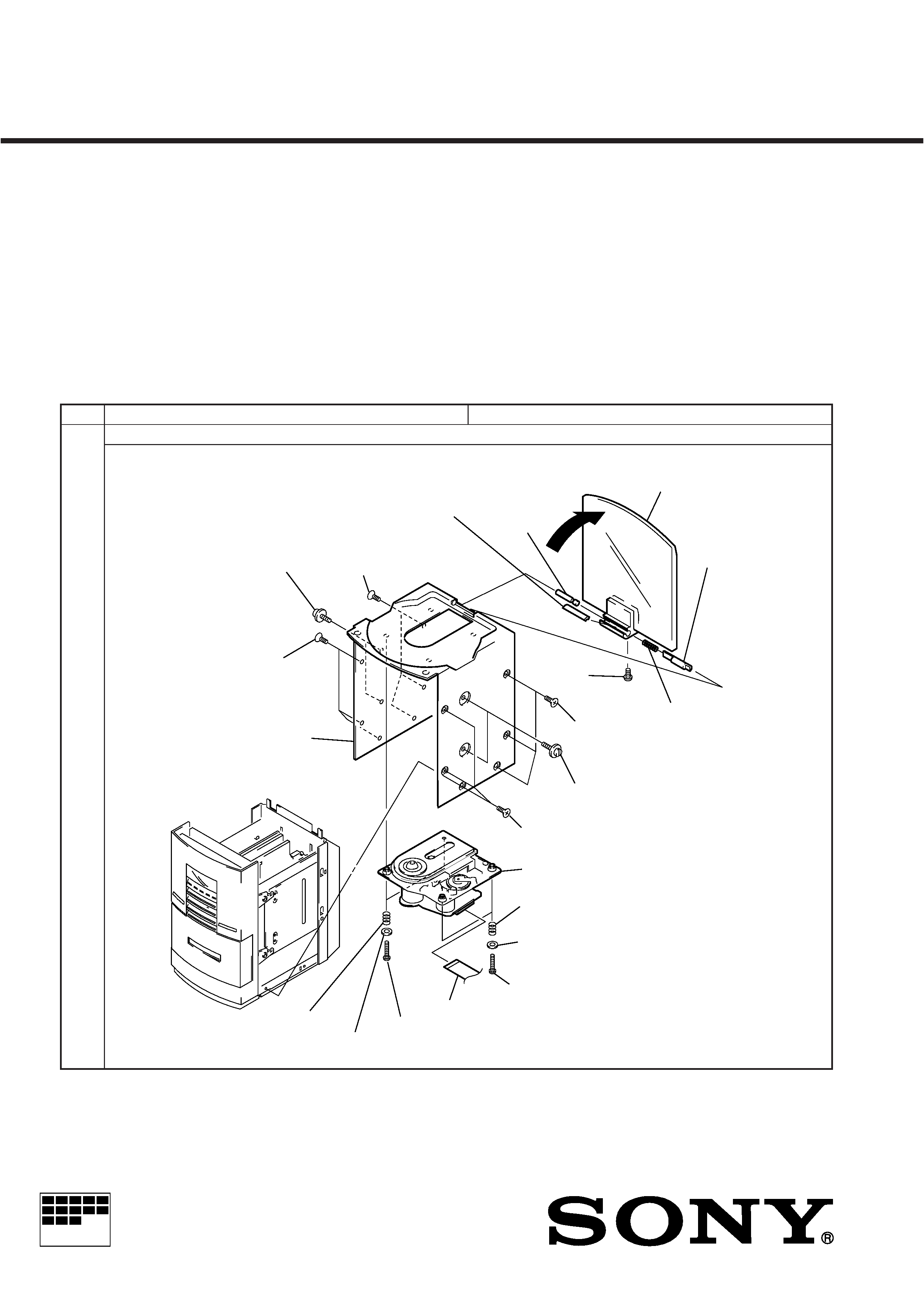
2-1. CD DOOR, CD BASE AND BASE UNIT
!¶ Two springs
(compression)
1 Open the CD door.
2 Bar rubber
4 CD player hinge
6 Hinge pin
5 Hinge spring
3 Screw
(P2x5)
!¡ Three screws (K3x8)
!º Two hook screws
!TM Three screws (K3x8)
@¡ Base unit
@º Two springs (compression)
!ª Two washers
!· Two screws (TPG P2x8)
!¢ Wire (Flat type)
! Two screws (TPG P2x8)
!§ Two washers
!£ CD base
9 Three screws (K3x8)
7 Two hook screws
8 Three screws (K3x8)
COMPACT DISC DECK RECEIVER
HCD-ED1A
2
Page
HCD-ED1
HCD-ED1A
13
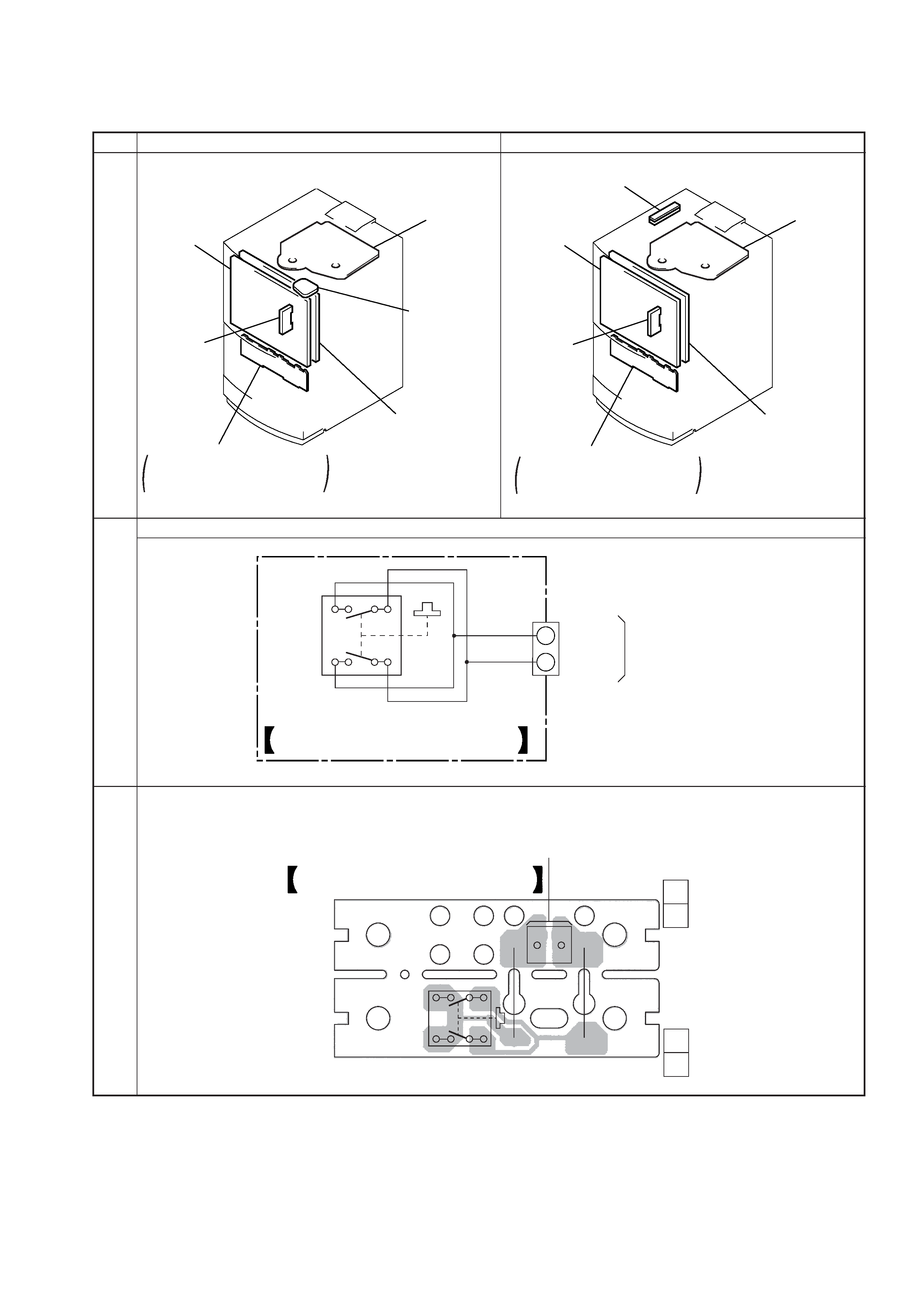
DISPLAY
board
RELAY board
CD DOOR SW
board
BD board
CONTROL BLK ASSY
THIS BLOCK IS SUPPLIED
AS THE ASSEMBLED BLOCK
LED board
DISPLAY
board
CD DOOR SW board
RELAY board
BD board
CONTROL BLK ASSY
THIS BLOCK IS SUPPLIED
AS THE ASSEMBLED BLOCK
LED board
DIFFERENCE TABLE
31
CD DOOR SW BOARD
1
2
D GND
CLOSE SW
M1013 2P
TO
RELAY BOARD
W103
S212
CD DOOR SWITCH
35
1
W104
J211
J210
CD DOOR
210-P125-260
SW PCB
210-P125-270
S212
DOOR SW PCB
TO
RELAY BOARD
W103
CD DOOR SW BOARD
1-671-921-
1-671-922- (11)
11
(11)
11
HCD-ED1A
3
· Abbreviation
EE
: East European model
HK
: Hong Kong model
SP
: Singapore model
MY
: Malaysia model
NOTE:
· Items marked "*" are not stocked since they are
seldom required for routine service. Some delay
should be anticipated when ordering these items.
Page
HCD-ED1
HCD-ED1A
45
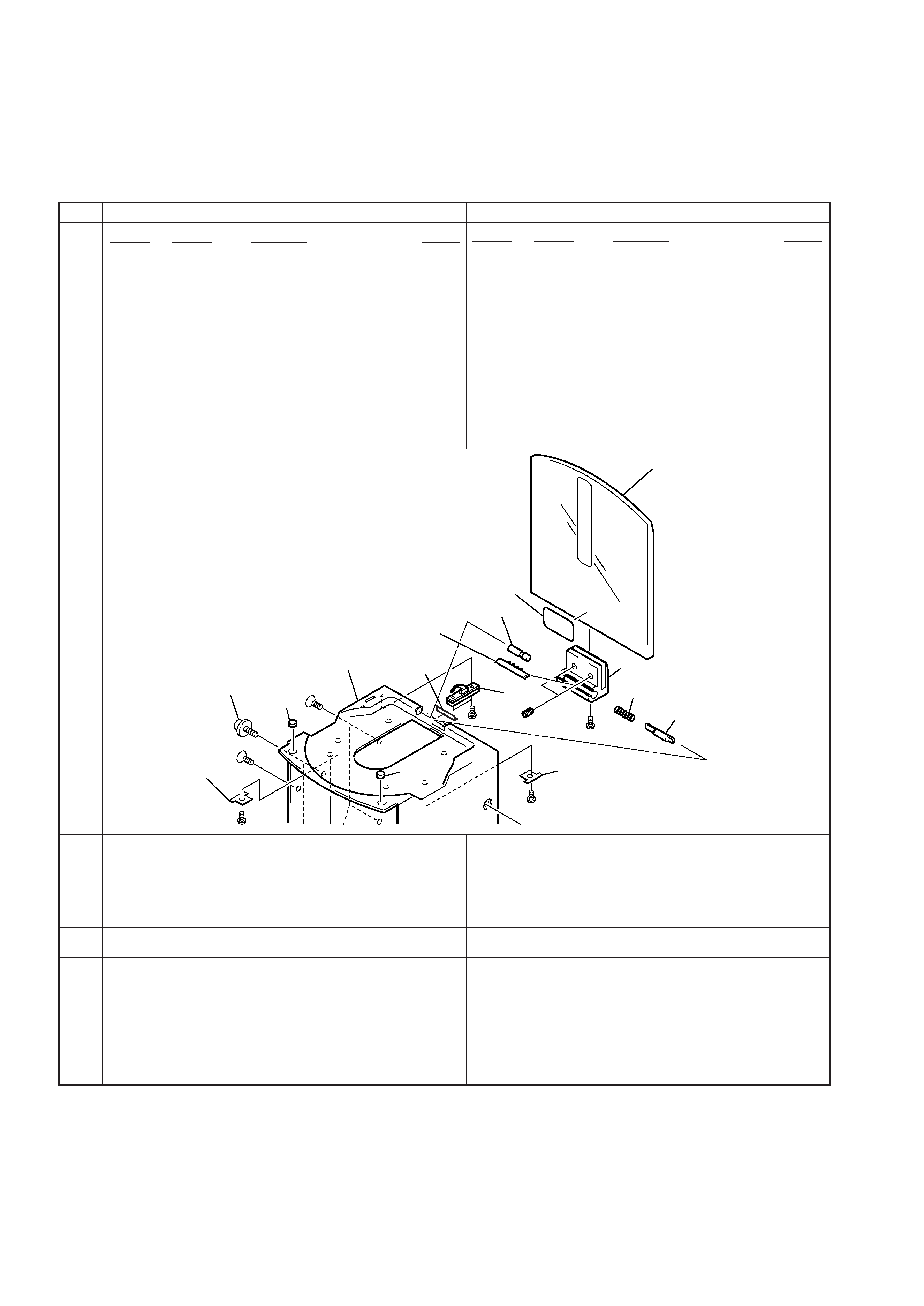
***EXPLODED VIEW***
1
4-997-375-01 GLASS DOOR W/PRINGING
3
4-997-355-01 DOOR HINGE
4
4-997-365-01 HINGE PIN
5
4-997-370-01 BAR RUBBER
6
4-997-356-01 HINGE SPRING
7
4-997-349-01 CD BASE
* 16
A-4407-244-A CD DOOR SW BOARD, COMPLETE
17
4-977-376-01 STOP SPRING
18
4-977-371-01 STOPPER
NOT USED
Ref. No.
Part No.
Description
Remark
***EXPLODED VIEW***
1
4-214-091-01 GLASS DOOR W/PRINGING
3
4-214-085-01 DOOR HINGE
4
4-214-088-01 HINGE PIN
5
4-214-090-01 BAR RUBBER
6
4-214-086-01 HINGE SPRING
7
4-214-084-01 CD BASE
* 16
A-4417-329-A CD DOOR SW BOARD, COMPLETE
17
4-214-956-01 STOP SPRING
18
4-997-371-01 STOPPER
19
4-214-092-01 CD PLAYER HINGE
Ref. No.
Part No.
Description
Remark
1
2
4
5
6
7
17
9
9
18
10
18
16
19
3
#2
#3
#3
#1
#4
#14
#2
* 53
4-214-094-01 REAR PANEL (AEP)
* 53
4-214-095-01 REAR PANEL (UK)
* 53
4-214-089-01 REAR PANEL (EE,CIS)
* 53
4-214-097-01 REAR PANEL (MY,SP)
* 53
4-214-096-01 REAR PANEL (HK)
* 53
4-997-368-11 REAR PANEL (AEP)
* 53
4-997-368-21 REAR PANEL (UK)
* 53
4-997-368-31 REAR PANEL (EE,CIS)
* 53
4-997-368-51 REAR PANEL (MY,SP)
* 53
4-997-368-61 REAR PANEL (HK)
46
111
4-997-357-01 GEAR HOLDER
47
111
4-214-087-01 GEAR HOLDER
***ELECTRICAL PARTS LIST***
*
A-4407-244-A CD DOOR SW BOARD, COMPLETE
***************************
S211
1-771-298-11 SWITCH, PUSH (CD DOOR)
51
***ELECTRICAL PARTS LIST***
*
A-4417-329-A CD DOOR SW BOARD, COMPLETE
***************************
S211
1-771-264-11 SWITCH, PUSH (CD DOOR)
***HARDWARE LIST***
NOT USED
58
***HARDWARE LIST***
#14
7-621-283-00 +P2x5
1
Model Name Using Similar Mechanism
NEW
Base Unit Type
BU17-BD19
Optical Pick-up Type
KSS-213BA/S-N
Model Name Using Similar Mechanism
NEW
Tape Transport Mechanism Type
CMAL2Z076A
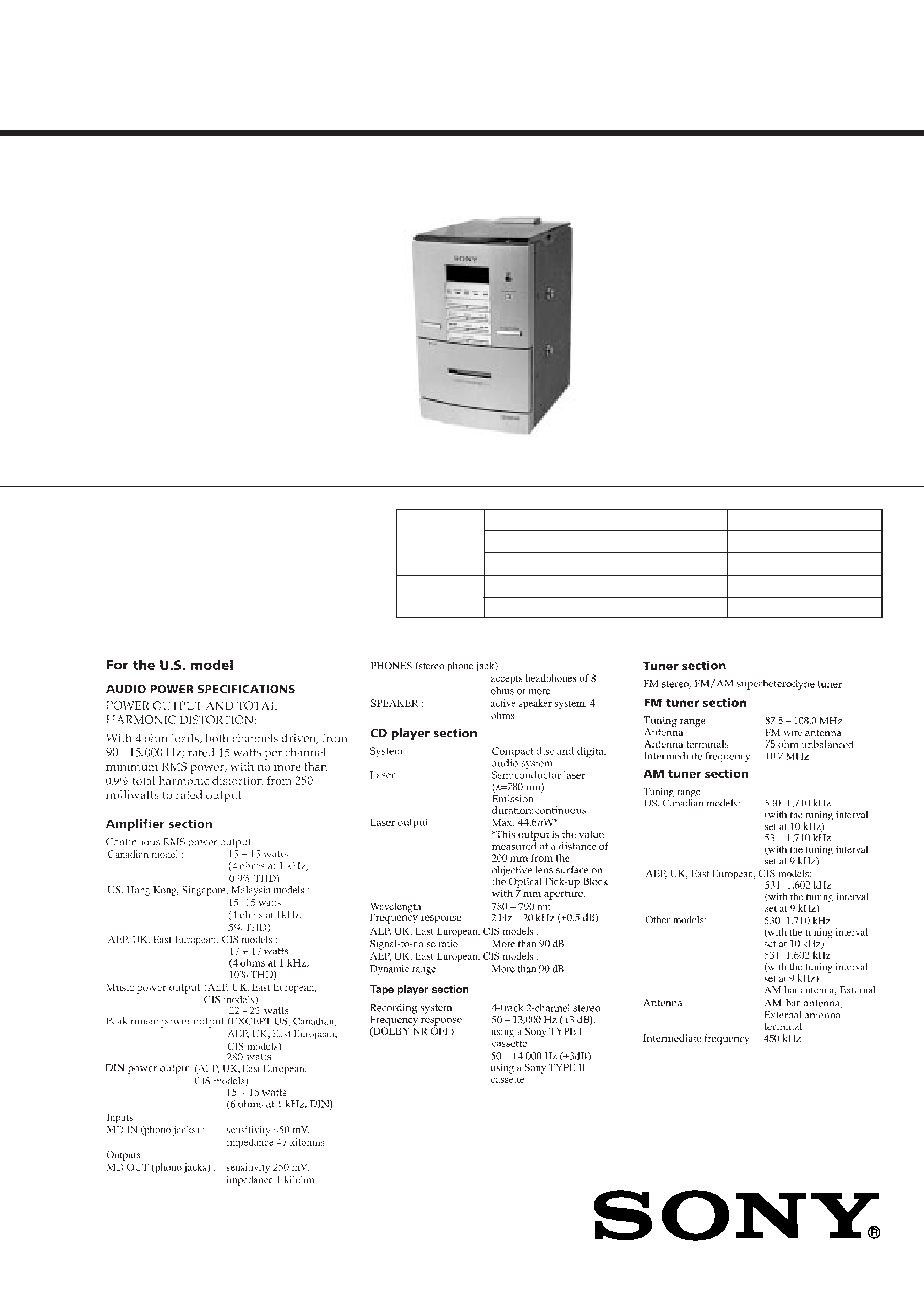
SERVICE MANUAL
COMPACT DISC DECK RECEIVER
HCD-ED1 is the tuner, deck, CD and
amplifier section in CMT-ED1.
US Model
Canadian Model
AEP Model
UK Model
E Model
HCD-ED1
-- Continued on next page --
This stereo system is equipped with the Dolby* B-
type noise reduction system.
*Dolby noise reduction manufactured under license
from Dolby Laboratories Licensing Corporation.
"DOLBY" and the double-D symbol a are trade-
marks of Dolby Laboratories Licensing Corporation.
CD
SECTION
TAPE
DECK
SECTION
SPECIFICATIONS
9-922-706-12
2001F0200-1
© 2001.6
Sony Corporation
Home Audio Company
Shinagawa Tec Service Manual Production Group
2
ATTENTION AU COMPOSANT AYANT RAPPORT
À LA SÉCURITÉ!!
LES COMPOSANTS IDENTIFIÉS PAR UNE MARQUE !SUR
LES DIAGRAMMES SCHÉMATIQUES ET LA LISTE DES
PIÈCES SONT CRITIQUES POUR LA SÉCURITÉ DE
FONCTIONNEMENT. NE REMPLACER CES COMPOSANTS
QUE PAR DES PIÈCES SONY DONT LES NUMÉROS
SONT DONNÉS DANS CE MANUEL OU DANS LES
SUPPLÉMENTS PUBLIÉS PAR SONY.
SAFETY CHECK-OUT
After correcting the original service problem, perform the follow-
ing safety checks before releasing the set to the customer:
Check the antenna terminals, metal trim, "metallized" knobs, screws,
and all other exposed metal parts for AC leakage. Check leakage as
described below.
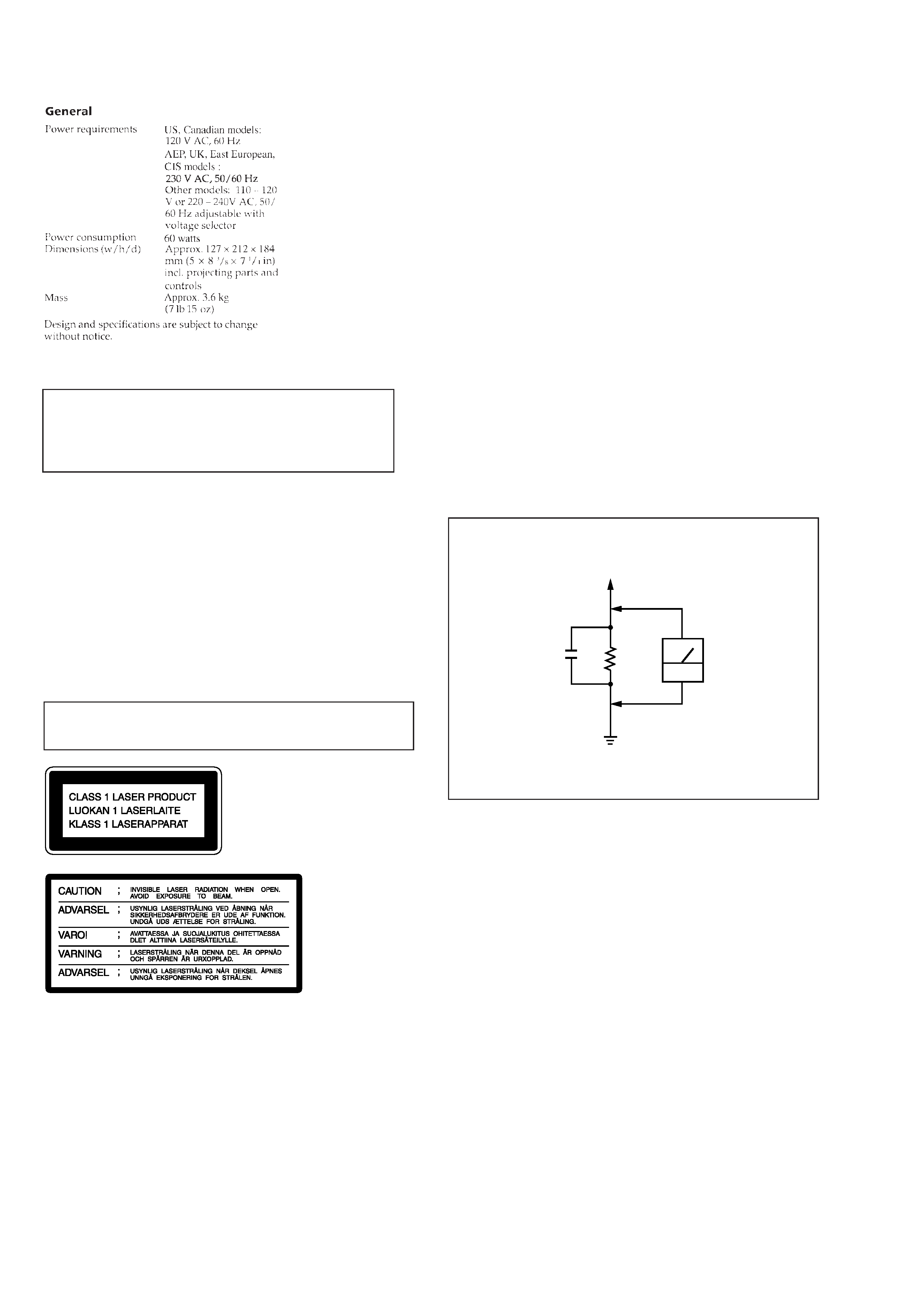
LEAKAGE
The AC leakage from any exposed metal part to earth Ground and
from all exposed metal parts to any exposed metal part having a
return to chassis, must not exceed 0.5 mA (500 microampers). Leak-
age current can be measured by any one of three methods.
1. A commercial leakage tester, such as the Simpson 229 or RCA
WT-540A. Follow the manufacturers' instructions to use these
instruments.
2. A battery-operated AC milliammeter. The Data Precision 245
digital multimeter is suitable for this job.
3. Measuring the voltage drop across a resistor by means of a VOM
or battery-operated AC voltmeter. The "limit" indication is 0.75
V, so analog meters must have an accurate low-voltage scale.
The Simpson 250 and Sanwa SH-63Trd are examples of a pas-
sive VOM that is suitable. Nearly all battery operated digital
multimeters that have a 2V AC range are suitable. (See Fig. A)
Fig. A. Using an AC voltmeter to check AC leakage.
SAFETY-RELATED COMPONENT WARNING !!
COMPONENTS IDENTIFIED BY MARK ! OR DOTTED LINE
WITH MARK ! ON THE SCHEMATIC DIAGRAMS AND IN
THE PARTS LIST ARE CRITICAL TO SAFE OPERATION.
REPLACE THESE COMPONENTS WITH SONY PARTS
WHOSE PART NUMBERS APPEAR AS SHOWN IN THIS
MANUAL OR IN SUPPLEMENTS PUBLISHED BY SONY.
Laser component in this product is capable of emitting radiation
exceeding the limit for Class 1.
This appliance is classified as
a CLASS 1 LASER product.
The CLASS 1 LASER PROD-
UCT MARKING is located on
the rear exterior.
This caution
label is located
inside the unit.
CAUTION
Use of controls or adjustments or performance of procedures
other than those specified herein may result in hazardous ra-
diation exposure.
Notes on chip component replacement
· Never reuse a disconnected chip component.
· Notice that the minus side of a tantalum capacitor may be
damaged by heat.
Flexible Circuit Board Repairing
· Keep the temperature of soldering iron around 270°C
during repairing.
· Do not touch the soldering iron on the same conductor of the
circuit board (within 3 times).
· Be careful not to apply force on the conductor when soldering
or unsoldering.
AC
voltmeter
(0.75V)
1.5k
0.15
µF
Parts on Set
Earth Ground