SERVICE MANUAL
COMPACT DISC DECK RECEIVER
AEP Model
SPECIFICATIONS
HCD-E301
Ver 1.0 2001.05
HCD-E301 is the amplifier, CD player, tape
deck and tuner section in CMT-E301.
9-873-906-11
Sony Corporation
2001E0500-1
Home Audio Company
C
2001.5
Shinagawa Tec Service Manual Production Group
Amplifier section
DIN power output (rated) 4.5 + 4.5 W
(4
at 1 kHz, DIN)
Continuous RMS power output (reference)
5 + 5 W
(4
at 1 kHz, 10% THD)
Music power output (reference)
13 + 13 W
CD player section
System
Compact disc and digital
audio system
Laser
Semiconductor laser
(
=780 nm)
Emission duration:
continuous
Frequency response
20 Hz - 20 kHz (
±0.5 dB)
Tape player section
Recording system
4-track 2-channel stereo
Frequency response
50 - 13 000 Hz (
±3 dB),
using Sony TYPE I
cassette
Tuner section
FM stereo, FM/AM superheterodyne tuner
FM tuner section
Tuning range
87.5 - 108.0 MHz
Antenna
FM lead antenna
Intermediate frequency
10.7 MHz
AM tuner section
Tuning range
531 -1 602 kHz
(with the interval set at
9 kHz)
Antenna
Built-in ferrite bar antenna
Intermediate frequency
450 kHz
General
Power requirements
230 V AC, 50/60 Hz
Power consumption
30 W
0.9 W (in the standby
mode)
Dimensions (w/h/d):
Approx. 145
× 238 × 238 mm
Mass:
Approx. 2.8 kg
Design and specifications are subject to change
without notice.
CD
Model Name Using Similar Mechanism
HCD-EP30
Section
CD Mechanism Type
CS-21SC-1280
TAPE
Model Name Using Similar Mechanism
HCD-EP30
Section
Tape Transport Mechanism Type
TCM125-2
2
HCD-E301
Notes on chip component replacement
· Never reuse a disconnected chip component.
· Notice that the minus side of a tantalum capacitor may be dam-
aged by heat.
Flexible Circuit Board Repairing
· Keep the temperature of the soldering iron around 270 °C dur-
ing repairing.
· Do not touch the soldering iron on the same conductor of the
circuit board (within 3 times).
· Be careful not to apply force on the conductor when soldering
or unsoldering.
CAUTION
Use of controls or adjustments or performance of procedures
other than those specified herein may result in hazardous ra-
diation exposure.
SAFETY-RELATED COMPONENT WARNING!!
COMPONENTS IDENTIFIED BY MARK 0 OR DOTTED
LINE WITH MARK 0 ON THE SCHEMATIC DIAGRAMS
AND IN THE PARTS LIST ARE CRITICAL TO SAFE
OPERATION. REPLACE THESE COMPONENTS WITH
SONY PARTS WHOSE PART NUMBERS APPEAR AS
SHOWN IN THIS MANUAL OR IN SUPPLEMENTS PUB-
LISHED BY SONY.
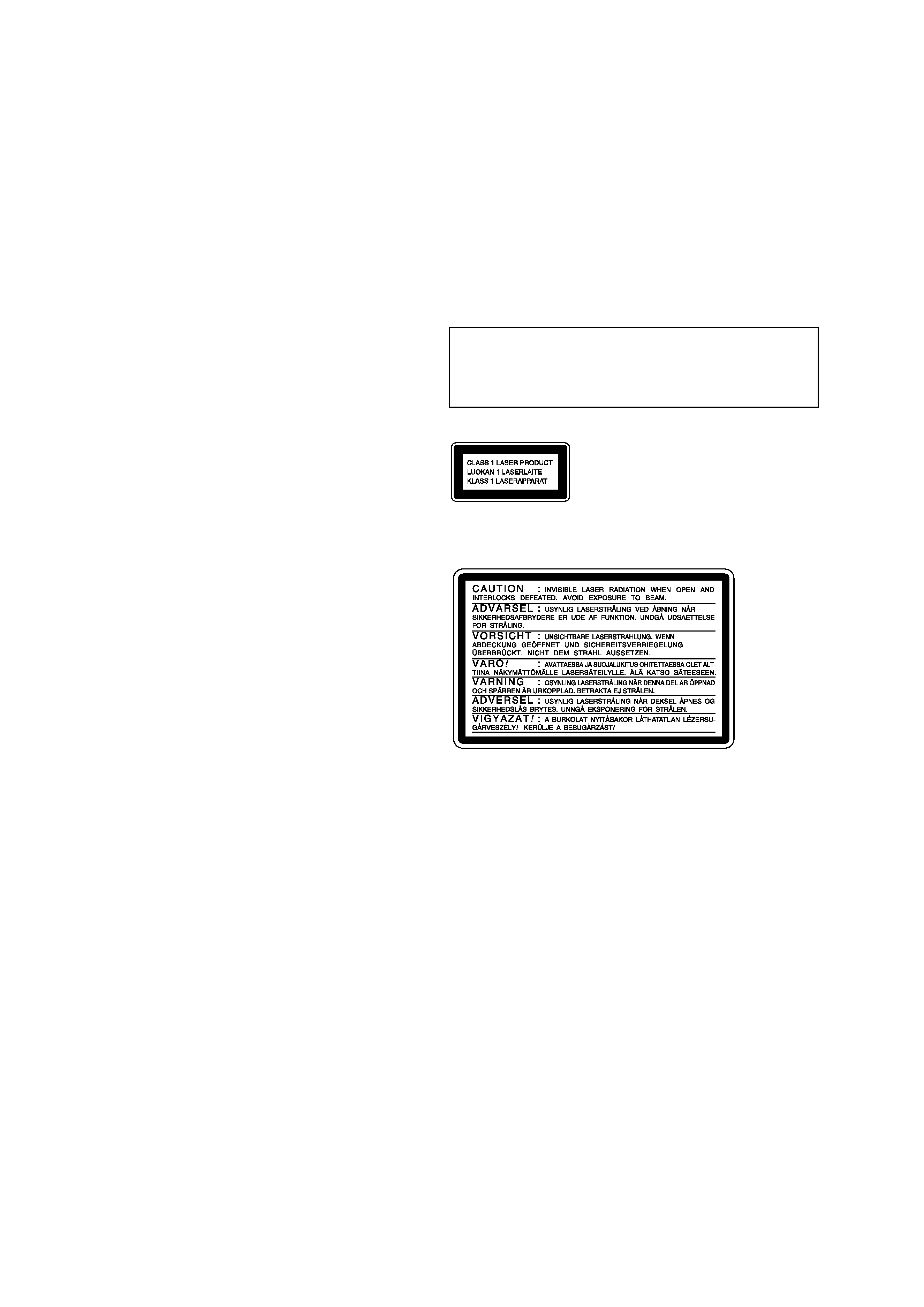
The following caution label is located inside the unit.
This appliance is classified as
a CLASS 1 LASER product.
The CLASS 1 LASER
PRODUCT MARKING is
located on the rear exterior.
TABLE OF CONTENTS
1.
SERVICING NOTES ................................................ 3
2.
GENERAL ................................................................... 4
3.
DISASSEMBLY
3-1. Disassembly Flow ...........................................................
6
3-2. Front Panel Section .........................................................
7
3-3. MAIN Board ...................................................................
7
3-4. CD Cabinet Section .........................................................
8
3-5. CD Mechanism Deck (CS-21SC-1280) .........................
8
3-6. Tape Mechanism Deck (TCM125-2) ..............................
9
3-7. Cassette Lid .....................................................................
9
4.
MECHANICAL ADJUSTMENTS ....................... 10
5.
ELECTRICAL ADJUSTMENTS ......................... 10
6.
DIAGRAMS
6-1. Note for Printed Wiring Boards and
Schematic Diagrams ....................................................... 13
6-2. Schematic Diagram MAIN Board (1/2) .................. 14
6-3. Schematic Diagram
MAIN (2/2)/HEADPHONE Boards ......................... 15
6-4. Printed Wiring Boards
MAIN/HEADPHONE Boards .................................. 16
6-5. Printed Wiring Board CASSETTE Board ............... 17
6-6. Schematic Diagram CASSETTE Board .................. 17
6-7. Printed Wiring Board DISPLAY Board .................. 18
6-8. Schematic Diagram DISPLAY Board ..................... 19
6-9. Schematic Diagram POWER Board ........................ 20
6-10. Printed Wiring Board POWER Board ..................... 21
6-11. IC Pin Function Description ........................................... 23
7.
EXPLODED VIEWS
7-1. Cabinet Section ............................................................... 24
7-2. Front Panel Section-1 ...................................................... 25
7-3. Front Panel Section-2 ...................................................... 26
7-4. CD Cabinet Section ......................................................... 27
8.
ELECTRICAL PARTS LIST ............................... 28
3
HCD-E301
NOTES ON HANDLING THE OPTICAL PICK-UP
BLOCK OR BASE UNIT
The laser diode in the optical pick-up block may suffer electro-
static break-down because of the potential difference generated
by the charged electrostatic load, etc. on clothing and the human
body.
During repair, pay attention to electrostatic break-down and also
use the procedure in the printed matter which is included in the
repair parts.
The flexible board is easily damaged and should be handled with
care.
NOTES ON LASER DIODE EMISSION CHECK
The laser beam on this model is concentrated so as to be focused
on the disc reflective surface by the objective lens in the optical
pick-up block. Therefore, when checking the laser diode emis-
sion, observe from more than 30 cm away from the objective lens.
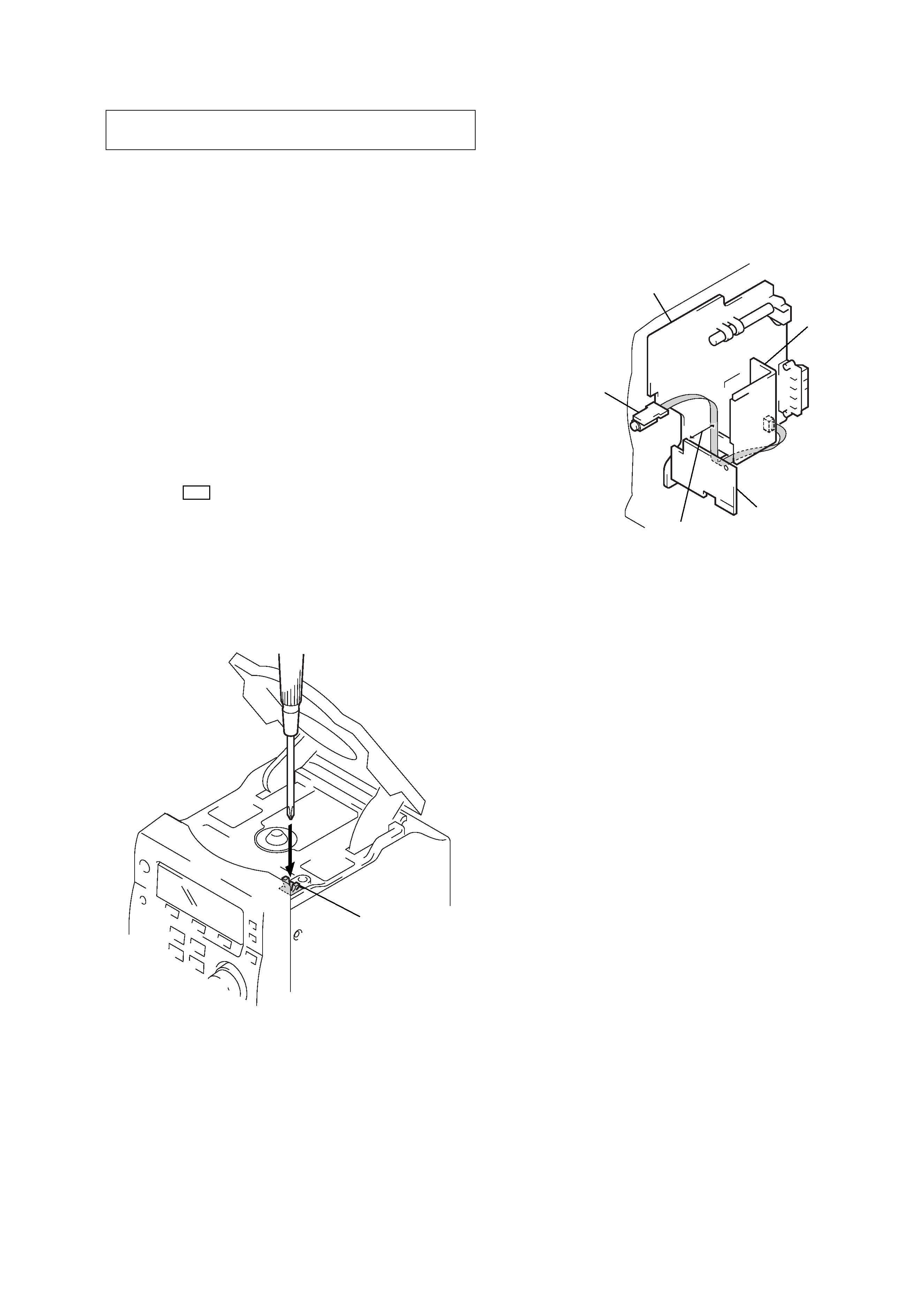
LASER DIODE AND FOCUS SEARCH OPERATION
CHECK
1. Press the I/1 button to the power ON with no disc inserted
and press the [CD] button.
2. Open the lid for CD.
3. Turn on SW600 as following figure.
4. Confirm the laser diode emission while observing the object-
ing lens. When there is no emission, Auto Power Control cir-
cuit or Optical Pick-up is broken.
Objective lens moves up and down five times for the focus
search.
SECTION 1
SERVICING NOTES
TO PREVENT `TAPE OSCILLATION SOUND AT VOLUME'
MAXIMUM SETTING (W/O TAPE)
Headphone wire dressing:
a.) Draw the wire from Main board to Headphone Jack board along
the bottom side of heatsink.
b.) The wire must be kept away from the top side of Cassette board
at least 30 mm.
SW600
CASSETTE board
MAIN board
HEADPHONE
board
at least 30 mm
heatsink
4
HCD-E301
SECTION 2
GENERAL
This section is extracted from
instruction manual.
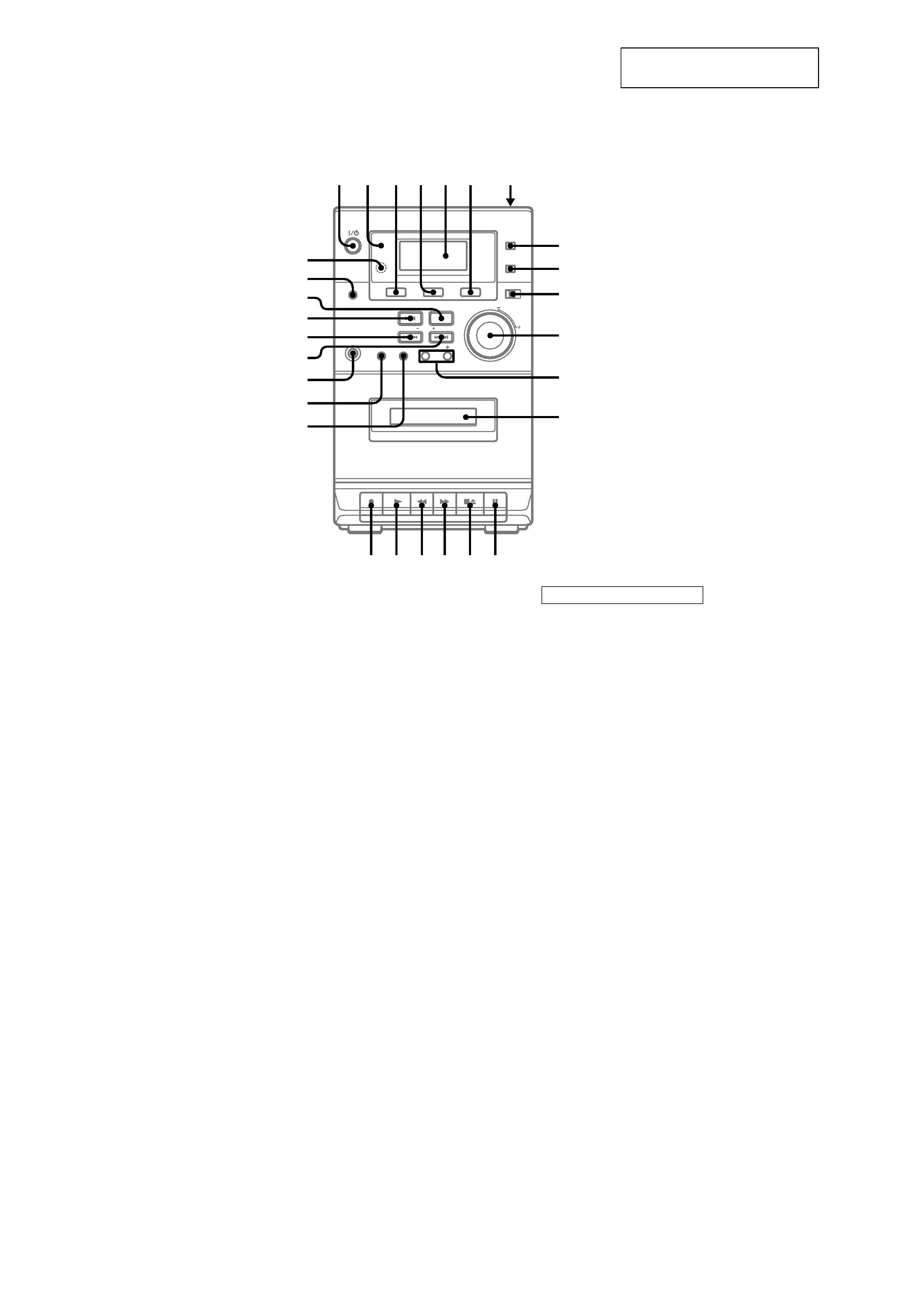
LOCATION OF CONTROLS
Front Panel
Cassette compartment qd (12)
CD 4 (8, 9, 13, 15)
Display Window 5 (9, 18)
ENTER/PGM w; (7, 8, 9, 10, 12,
15)
ISS 0 (13)
MEGA BASS 8 (14)
MONO STEREO 0 (11)
MUSIC MENU 9 (14)
PHONES jack ws
PRESET +/ qs (10, 11)
REMAIN 4 (9)
Remote sensor wk
REPEAT wj (8)
SHUFFLE wa (8)
TAPE 3 (12)
TIMER indicator 2 (15)
TUNER 6 (10, 13, 15)
TUNER MEM w; (10)
TUNING + wd (10, 11)
TUNING wf (10, 11)
VOLUME control qa (15)
1
2
3456
7
q;
9
8
qa
qs
w;
wa
ws
wd
wf
wg
wh
wj
wk
qd
qf
qj qh
ql qk
qg
BUTTON DESCRIPTIONS
@/1 (power) 1 (6, 10)
CD
. m (go back) wf (8, 9)
M > (go forward) wd (8, 9)
u (play/pause) wg (8, 9)
Z PUSH OPEN/CLOSE 7 (8)
x (stop) wh (8, 9)
TAPE
M (fast forward) qh (12)
X (pause) qf (12, 13)
N (play) qk (12, 15)
z (recording) ql (13)
m (rewind) qj (12)
xZ (stop/eject) qg (12, 13)
5
HCD-E301
CD/REMAIN 3 (8, 9, 13, 15)
CLOCK/TIMER/SLEEP SET qf
(7, 15)
MEGA BASS 2 (14)
MUSIC MENU w; (14)
PRESET +/ qj (10, 11)
REPEAT qs (8)
SHUFFLE 7 (8)
TAPE ql (12)
TIMER ON/OFF qd (15)
TUNER/BAND 5 (10, 13, 15)
TUNER MEM/ENTER/PGM 6
(7, 8, 9, 10, 11, 15)
TUNING/CLOCK/TIMER +/
qk (7, 10, 11, 15)
VOLUME +/ 4 (15)
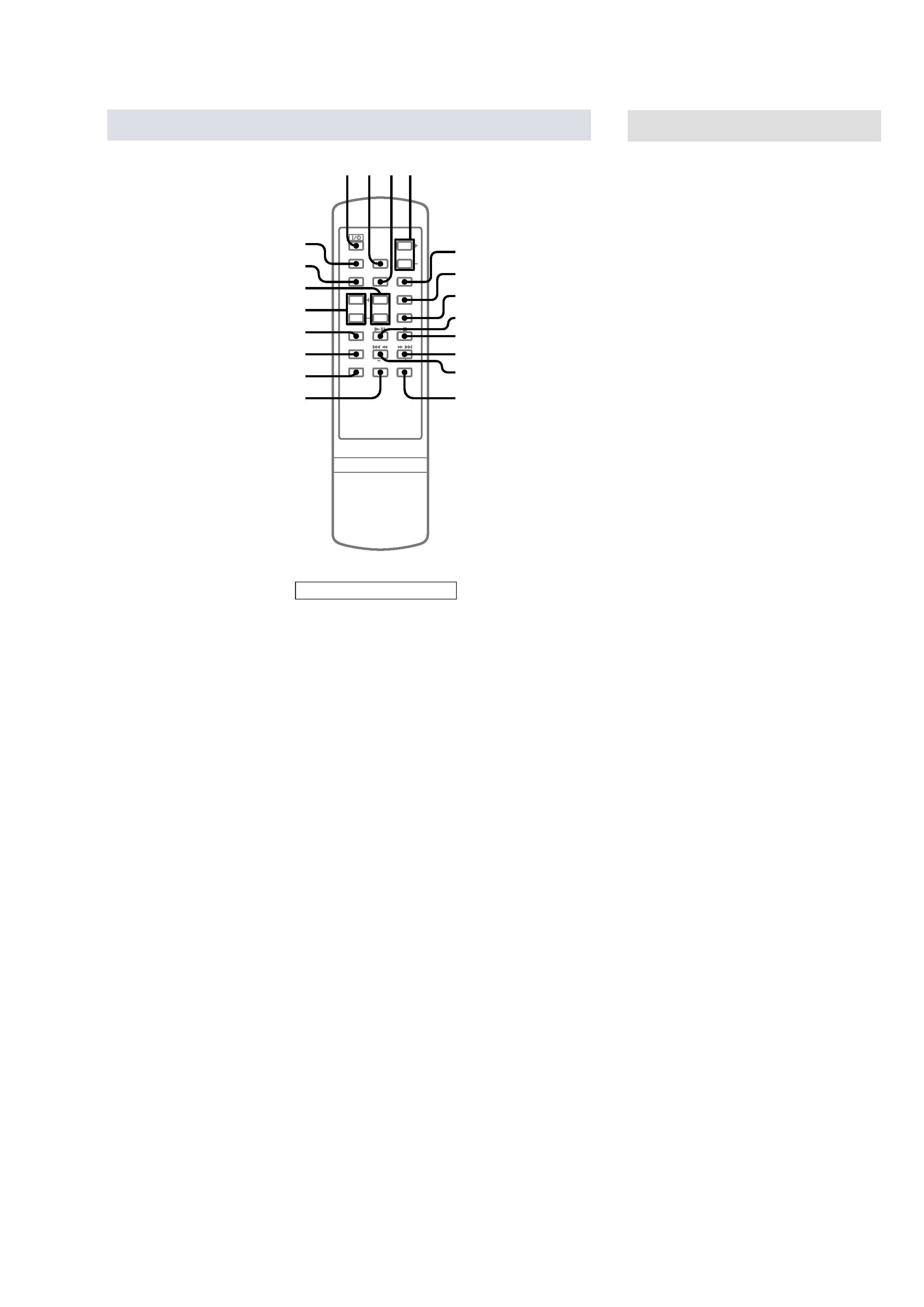
BUTTON DESCRIPTIONS
M (fast forward) > (go
forward) 0 (8, 9)
. (go back) m (rewind) qa
(8, 9)
u (play/pause) 8 (8, 9)
`/1 (power) 1 (6, 10)
x (stop) 9 (8, 9)
Remote Control
123 4
5
6
7
8
9
q;
qa
qs
qf
qd
qg
qh
qj
qk
ql
w;
Setting the time
1 Turn on the system.
2 Press CLOCK/TIMER/SLEEP SET on
the remote.
The clock indication appears.
3 Press TUNING/CLOCK/TIMER + or -- on
the remote repeatedly to set the time.
4 Press ENTER/PGM (TUNER MEM/
ENTER/PGM on the remote).
The clock starts working.
Tip
If you made a mistake, perform from step 2.
To change the preset time
Perform from step 2.
Note
The clock settings are canceled when you disconnect
the power cord or if a power failure occurs.