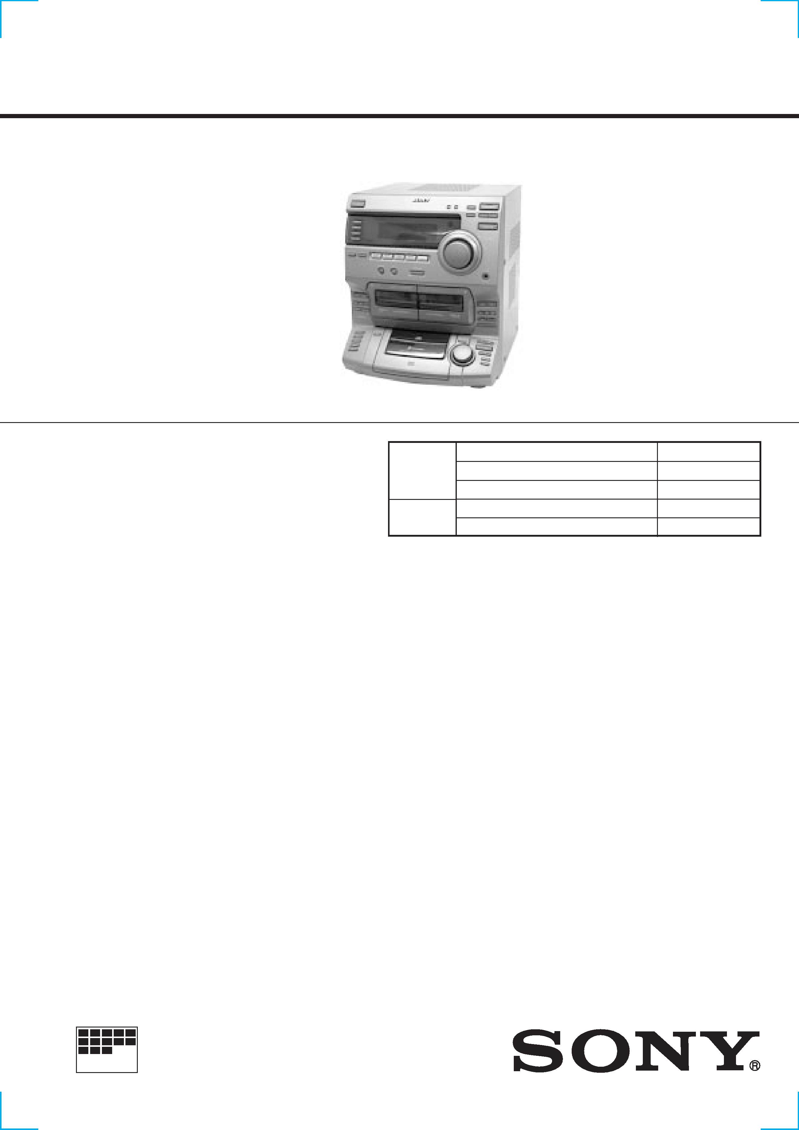
HCD-DR3/DR330/XB200
AEP Model
UK Model
HCD-XB200
E Model
HCD-DR3/DR330
Australian Model
HCD-DR3
SERVICE MANUAL
MICROFILM
Continued on next page
SPECIFICATIONS
COMPACT Hi-Fi STEREO SYSTEM
SPECIFICATIONS
HCD-DR3/DR330/XB200 is the tuner, deck,
CD and amplifier section in LBT-DR3/
DR330/XB200.
Model Name Using Similar Mechanism
HCD-G2500
Base Unit Type
KSM-213ECM/C2NP
Optical Pick-up Type
KSS-213E/C2N
Model Name Using Similar Mechanism
NEW
Tape Transport Mechanism Type
CWL-44-RR
CD
SECTION
TAPE
DECK
SECTION
Manufactured under license from Dolby Laboratories
Licensing Corporation.
"DOLBY" and the double-D symbol
aare trademarks
of Dolby Laboratories Licensing Corporation.
Amplifier section
(LBT-XB200)
DIN power output (Rated)
70W + 70W
(6
at 1 kHz DIN)
Continuous RMS power output (Reference)
80W + 80W
(6
at 1 kHz, 10%
THD)
Music power output (Reference)
140W + 140W
(6
at 1 kHz, 10%
THD)
(LBT-DR330/DR3)
The following measured at AC 110/220V, 60Hz ;
Continuous RMS power output (Reference)
85W + 85W
(6
at 1 kHz, 10%
THD)
DIN power output (Rated)
70W + 70W
(6
at 1 kHz, DIN)
The following measured at AC 120/240V, 60Hz ;
Continuous RMS power output (Reference)
100W + 100W
(6
at 1 kHz, 10%
THD)
DIN power output (Rated)
80W + 80W
(6
at 1 kHz, DIN)
Inputs
PHONO IN (phono jack):
sensitivity 3mV,
impedance 47 k
MD/VIDEO IN (phono jacks):
sensitivity 250mV,
impedance 47 k
Outputs
PHONOS (stereo phono jacks):
accepts headphones of 8
or more
MD/VIDEO OUT (phone jack):
voltage 250mV,
impedance 1 k
SPEAKER:
accepts impedance of 6 to
16
CD player section
System
Compact disc and digital
audio system
Laser
Semiconductor laser
(
= 780 nm)
Emission
duration: continuous
Laser output
Max. 44.6µW*
*This output is the value
measured at a distance of
200 mm from the objective
lens surface on the Optical
Pock-up Block with 7 mm
aperture.
Wavelength
780 790 nm
Frequency response
20Hz 20kHz (±0.5 dB)
Signal-to-noise retio
More than 90 dB
Dynamic range
More than 90 dB
DIGITAL OUT
(Square optical connector jack, rear panel)
Wavelength
600 nm
Output Level
18 dBm
Tape deck section
Recording system
4-track 2-channel stereo
Frequency response (DOLBY NR OFF)
60 13,000 Hz (±3 dB),
using a Sony TYPE I
cassette
Tuner section
FM stereo, FM/AM superheterodyne tuner
FM tunr section
Tuning range
87.5 108.0 MHz
(50 kHz step)
2
SAFETY-RELATED COMPONENT WARNING!!
COMPONENTS IDENTIFIED BY MARK
! OR DOTTED LINE WITH
MARK
! ON THE SCHEMATIC DIAGRAMS AND IN THE PARTS
LIST ARE CRITICAL TO SAFE OPERATION. REPLACE THESE
COMPONENTS WITH SONY PARTS WHOSE PART NUMBERS
APPEAR AS SHOWN IN THIS MANUAL OR IN SUPPLEMENTS
PUBLISHED BY SONY.
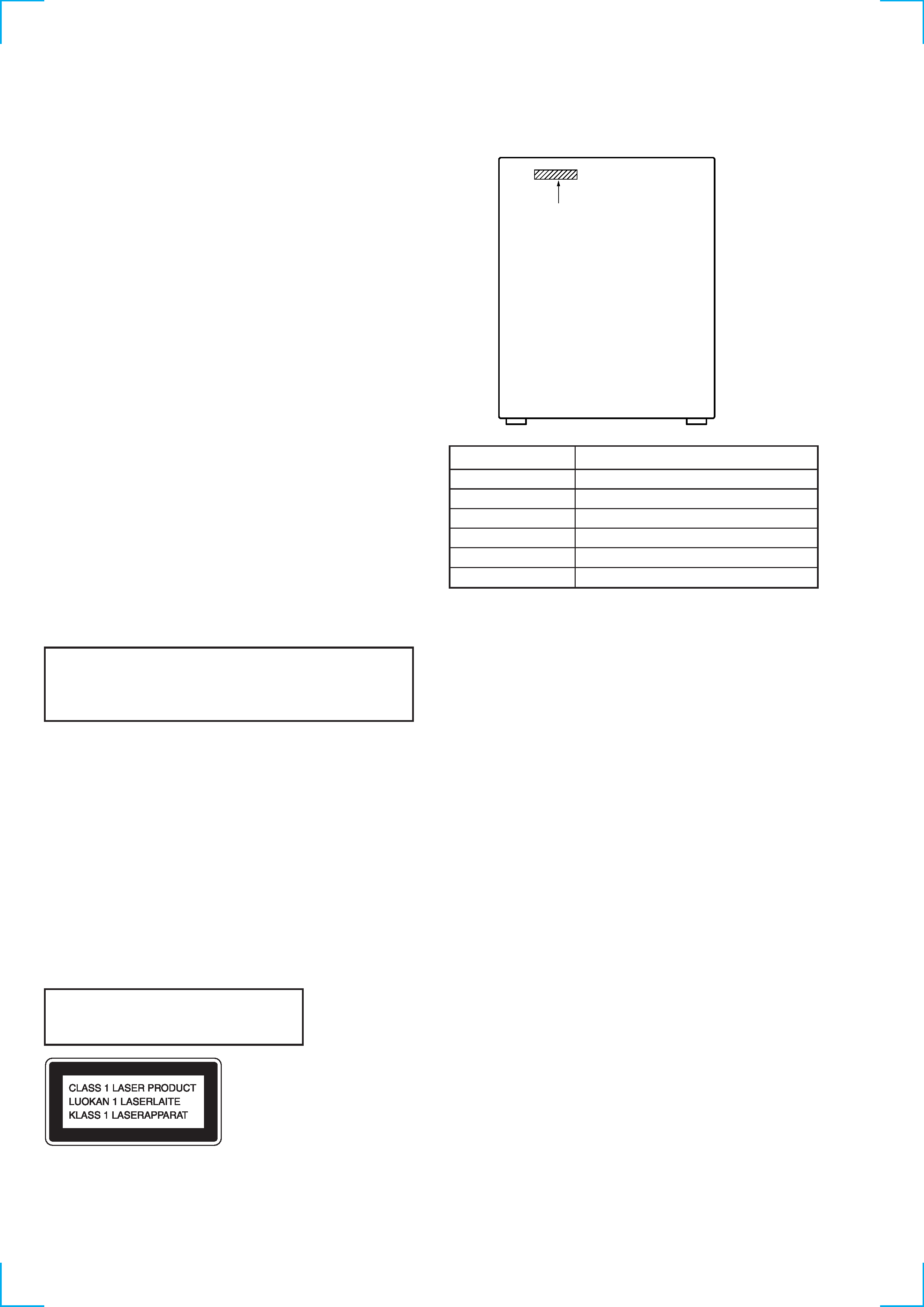
This appliance is classified as a CLASS 1 LASER product. The
CLASS 1 LASER PRODUCT MARKING is located on the rear
exterior.
The following caution label is located inside the unit.
Laser component in this product is capable
of emitting radiation exceeding the limit for
Class 1.
CAUTION
Use of controls or adjustments or performance of procedures
other than those specified herein may result in hazardous radiation
exposure.
Notes on chip component replacement
· Never reuse a disconnected chip component.
· Notice that the minus side of a tantalum capacitor may be
damaged by heat.
Flexible Circuit Board Repairing
· Keep the temperature of soldering iron around 270°C
during repairing.
· Do not touch the soldering iron on the same conductor of the
circuit board (within 3 times).
· Be careful not to apply force on the conductor when soldering
or unsoldering.
AM tuner section
Tuning renge
European and Middle Eastern models:
531 1,602 kHz
(with the tuning interval set at 9 kHz)
Other models:
531 1,602 kHz
(with the tuning interval set at 9 kHz)
530 1,710 kHz
(with the tuning interval set at 10 kHz)
Antenna
AM loop antenna,
External antenna terminals
Intermediate frequency
450 kHz
General
Power requirements
European model:
230 V AC, 50/60 Hz
Mexican model:
120V AC, 50/60 Hz
Australian model:
220 240 V AC, 50/60 Hz
Other models:
110 120 V or 220 240 V AC, 50/60 Hz Adjustable
with voltage selector
Power consumption
(HCD-DR330/DR3)
180W
(HCD-XB200)
135W
Dimensions(w/h/d)
Approx. 355
× 425 × 442 mm
(14
× 163/4 × 171/2 in) incl.
projecting parts and controls
Mass
Approx. 13.1 kg (28 lb 14 oz.)
Supplied accessories
AM loop antenna (1)
Remote RM-SG7B (1)
FM wire antenna (1)
Design and specifications are subject to change without notice
Parts No.
PARTS No.
MODEL
4-222-140-0
XB200 : AEP, UK
4-222-141-0
XB200 : EE, CIS
4-222-142-0
DR3 : E, SP, AR
4-222-143-0
DR3 : AUS
4-222-144-0
DR3 : MX
4-222-145-0
DR330
MODEL IDENTIFICATION
· Abbreviation
SP
: Singapore model
MX : Mexican model
AR
: Argentina model
AUS : Australian model
EE
: East European model

3
1. GENERAL ·········································································· 4
2. DISASSEMBLY
2-1.
Top Cover ··········································································· 5
2-2.
Front Panel Assy ································································· 5
2-3.
Main Section ······································································· 6
2-4.
Main Board ········································································· 6
2-5.
CD Mechanism Deck Section ············································ 7
2-6.
Tape Mechanism Deck Section ·········································· 7
2-7.
Cassette Doors ···································································· 8
2-8.
CD Chassis Assy ································································ 8
2-9.
Base Unit ············································································ 9
2-10. Turn Table ··········································································· 9
3. MECHANICAL ADJUSTMENTS ····························· 10
4. ELECTRICAL ADJUSTMENTS ······························· 10
5. DIAGRAMS
5-1.
Ciecuit Boards Location ··················································· 15
5-2.
Block Diagrams ································································ 16
Main Section ····································································· 16
Tuner/CD Section ····························································· 17
5-3.
Printed Wiring Board
Main Section ····························· 18
5-4.
Schematic Diagram
Main (1/3) Section ······················· 19
5-5.
Schematic Diagram
Main (2/3) Section ······················· 20
5-6.
Schematic Diagram
Main (3/3) Section ······················· 21
5-7.
Printed Wiring Board
AMP Section ····························· 22
5-8.
Schematic Diagram
AMP Section ································ 23
5-9.
Printed Wiring Board
CD Decoder Section ················· 24
5-10. Schematic Diagram
CD Decoder Section ···················· 25
5-11. Printed Wiring Board
Front Section ····························· 26
5-12. Schematic Diagram
Front (1/2) Section ······················· 27
5-13. Schematic Diagram
Front (2/2) Section ······················· 28
5-14. IC Pin Function Description ············································· 29
5-15. IC Block Diagrams ··························································· 31
6. EXPLODED VIEWS
6-1.
Top Cover Section ···························································· 33
6-2.
CD Door Section ······························································ 34
6-3.
Panel Section ···································································· 35
6-4.
Main Section ····································································· 36
6-5.
CD Mechanism Section ···················································· 37
6-6.
Base Unit Section (KSM-213ECM) ································· 38
7. ELECTRICAL PARTS LIST ······································· 39
TABLE OF CONTENTS
4
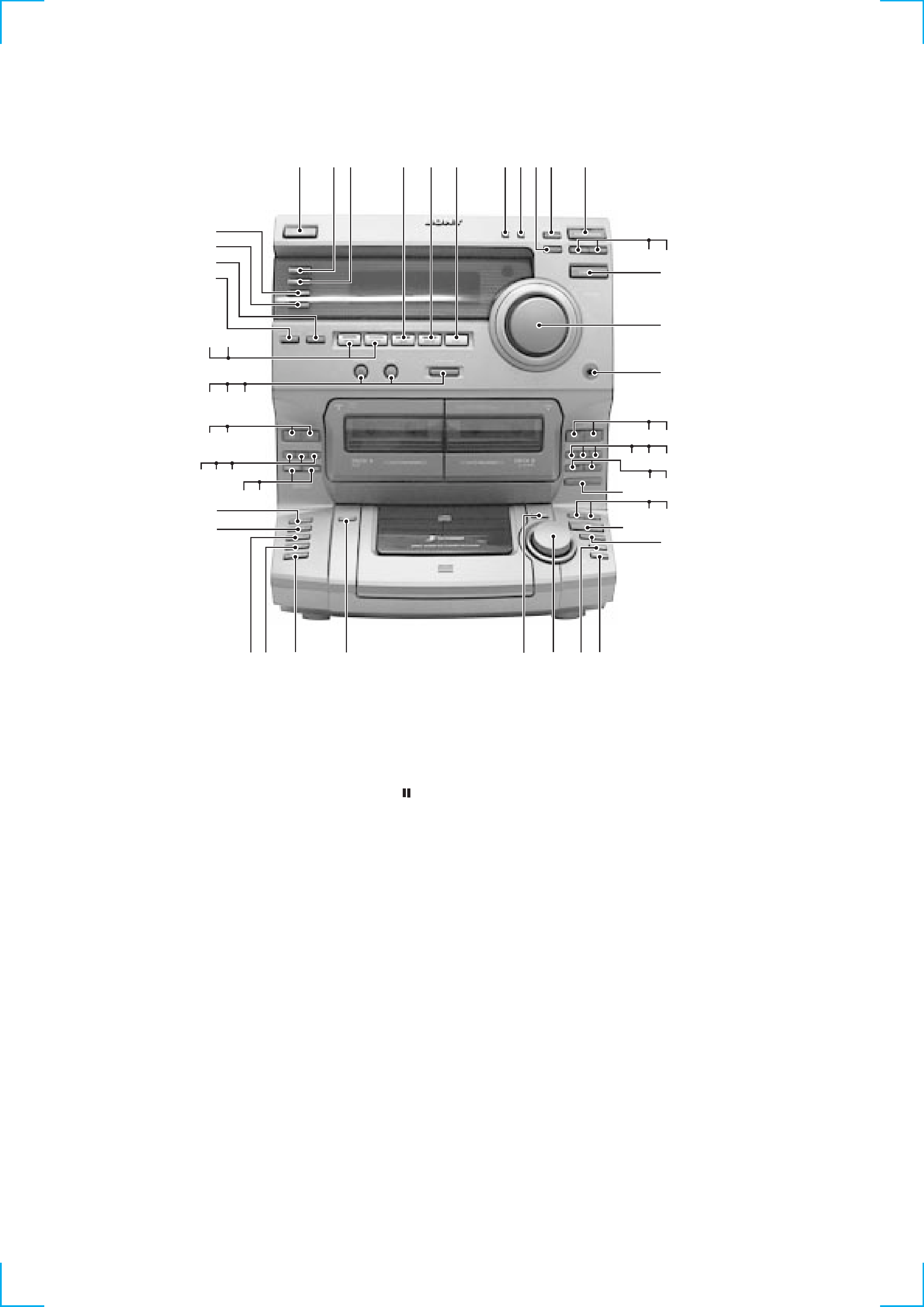
1
1/u (POWER) button
2
TUNING MODE button
3
STEREO/MONO button
4
TUNER MEMORY button
5
ENTER/NEXT button
6
TUNER/BAND button
7
TUNING button
8
TUNING + button
9
FUNCTION button
!º
VOLUME knob
!¡
PHONES jack
!TM
ª button (DECK B)
!£
· button (DECK B)
!¢
p button (DECK B)
!
0 button (DECK B)
!§
) button (DECK B)
!¶
P button (DECK B)
!·
r REC button (DECK B)
!ª
CD SYNCHRO button
@º
0 button (CD)
@¡
) button (CD)
@TM
fl button (CD)
@£
p button (CD)
@¢
REPEAT button
@
PLAY MODE button
@§
AMS knob
@¶
DISC SKIP button
@·
EDIT button
@ª
DISC 5 button
#º
DISC 4 button
#¡
DISC 3 button
#TM
DISC 2 button
#£
DISC 1 button
#¢
DIRECTION button
#
DOLBY NR button
#§
p button (DECK A)
SECTION 1
GENERAL
#¶
0 button (DECK A)
#·
) button (DECK A)
#ª
ª button (DECK A)
$º
· button (DECK A)
$¡
GROOVE button
$TM
DBFB button
$£
SURROUND button
$¢
SPECTRUM ANALYZER button
$
DISPLAY/DEMO button
$§
ROCK button
$¶
POPS button
$·
JAZZ button
$ª
SALSA button
%º
FLAT button
%¡
t /CLOCK SET button
%TM
SLEEP button
%£
TIMER REC button
%¢
DAILY button
1
%¢ %£
23
5
4
$ª
$·
%º
6
8
9
7
!¡
%TM
%¡
#TM
#£
@TM
0
$
$¢
!£
!TM
$¶
$§
$º
#ª
$TM
$¡
$£
@¡
@º
!·
!ª
@£
!¶
!§
!
!¢
@
@¶
#º
#¡
@¢
@§
@·
@ª
#
#¢
#¶
#§
#·
5
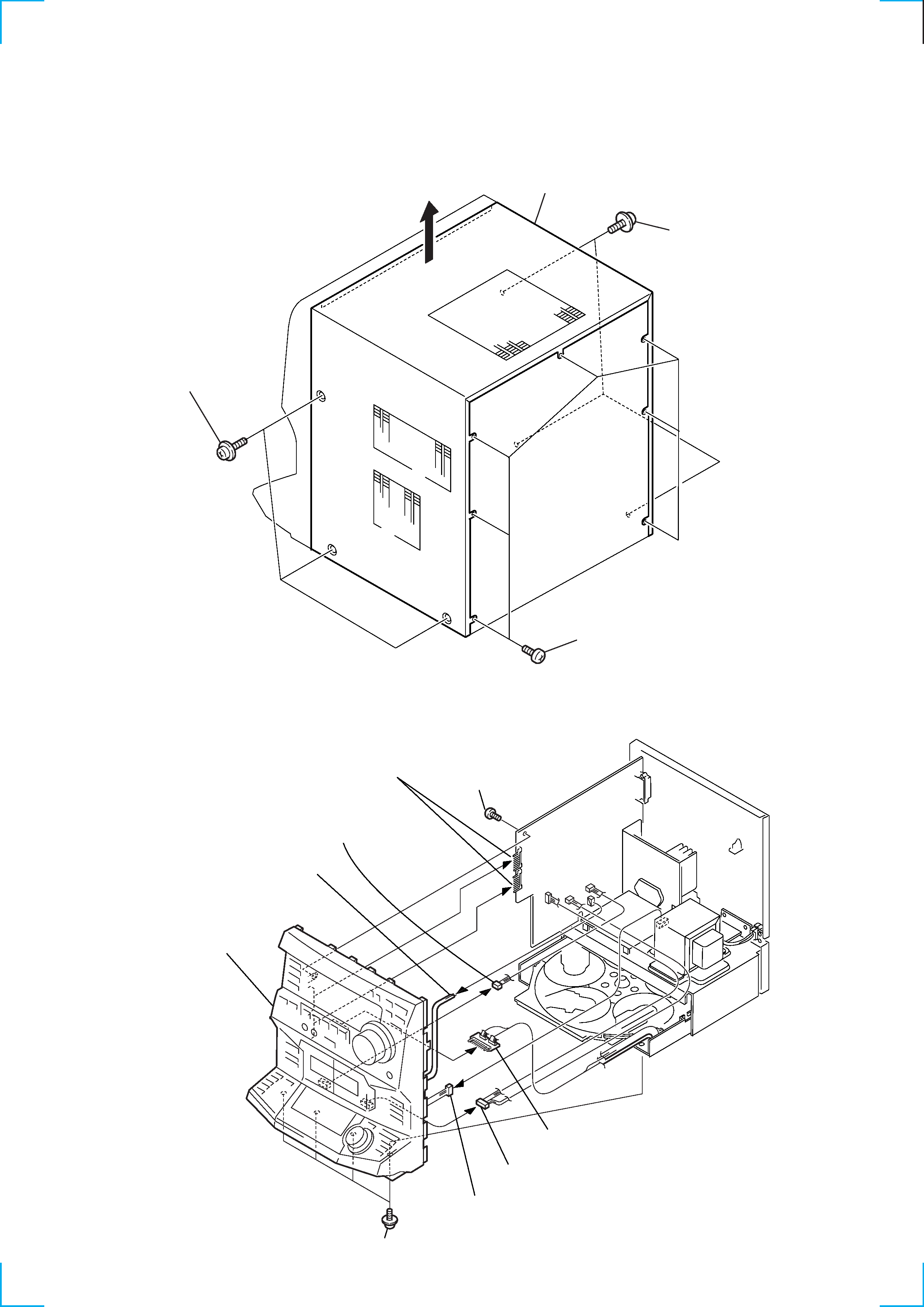
SECTION 2
DISASSEMBLY
Note :
Follow the disassembly procedure in the numerical order given.
2-1. TOP COVER
2-2. FRONT PANEL ASSY
2 Seven screws
1 Three screws
1 Three screws
3 Top cover
9 Front panel assy
6 Four screws
7 Screw
1 Connector
(to deck A)
2 Harness
(CN302)
4 Connector
(to deck B)
5 Connector
(CN702)
8 Board to board connector
(CN602)
(CN601)
3 Connector board
(CN11)