HCD-CL5MD
AEP Model
UK Model
E Model
Australian Model
SERVICE MANUAL
MICRO HiFi COMPONENT SYSTEM
Sony Corporation
Audio Entertainment Group
General Engineering Dept.
9-929-583-11
2001B1600-1
© 2001.2
-- Continued on next page --
SPECIFICATIONS
Ver 1.0 2001. 02
HCD-CL5MD is the tuner, deck, CD, MD and
amplifier section in CHC-CL5MD.
Model Name Using Similar Mechanism
NEW
CD Mechanism Type
CDM63B
Base Unit Type
BU-30BD61
Optical Pick-up Type
A-MAX.3
Model Name Using Similar Mechanism
HCD-ZX50MD
MD Mechanism Type
MDM-7B
Optical Pick-up Type
KMS-260B/K1NP
Model Name Using Similar Mechanism
NEW
Tape Transport Mechanism Type
TCM-230ASR41CL
CD
SECTION
MD
SECTION
TAPE DECK
SECTION
Amplifier section
AEP model:
DIN power output (Rated): 40 + 40 watts
(6 ohms at 1 kHz, DIN)
Continuous RMS power output (Reference):
50 + 50 watts
(6 ohms at 1 kHz, 10%
THD)
Music power output (Reference):
95 + 95 watts
(6 ohms at 1 kHz, 10%
THD)
Other models:
DIN power output (Rated): 40 + 40 watts
(6 ohms at 1 kHz, DIN)
Continuous RMS power output (Reference):
50 + 50 watts
(6 ohms at 1 kHz, 10%
THD)
Inputs
VIDEO (AUDIO) IN (phono jacks):
voltage 250 mV,
impedance 47 kilohms
CD DIGITAL IN (Supported sampling frequencies:
32 kHz, 44.1 kHz and 48 kHz)
Outputs
PHONES (stereo minijack):
accepts headphones of
8 ohms or more.
SPEAKER:
accepts impedance of 6 to
16 ohms.
CD player section
System
Compact disc and digital
audio system
Laser
Semiconductor laser
(=780 nm)
Emission duration:
continuous
Laser output
Max. 44.6
µW*
* This output is the value
measured at a distance
of 200 mm from the
objective lens surface on
the Optical Pick-up
Block with 7 mm
aperture.
Frequency response
20 Hz 20 kHz (
±0.5 dB)

2
HCD-CL5MD
MD deck section
System
MiniDisc digital audio
system
Laser
Semiconductor laser
(
=780 nm)
Emission duration:
continuous
Sampling frequency
44.1 kHz
Frequency response
20 Hz 20 kHz (
±0.5 dB)
Tape deck section
Recording system
4-track 2-channel stereo
Frequency response
40 13,000 Hz (
±3 dB),
using Sony TYPE I
cassettes
Tuner section
FM stereo, FM/AM superheterodyne tuner
FM tuner section
Tuning range
87.5 108.0 MHz
(50 kHz step)
Aerial
FM lead aerial
Aerial terminals
75 ohms unbalanced
Intermediate frequency
10.7 MHz
AM tuner section
Tuning range
AEP model:
531 1,602 kHz
(with the interval set at
9 kHz)
Other models:
531 1,602 kHz
(with the interval set at
9 kHz)
530 1,710 kHz
(with the interval set at
10 kHz)
Aerial
AM loop aerial
External aerial terminals
Intermediate frequency
450 kHz
General
Power requirements
AEP model:
230 V AC, 50/60 Hz
Australian and New Zealand models:
230 240 V AC, 50/60
Hz
Other models:
120 V, 220 V, 230 240
V AC, 50/60 Hz
Adjustable with voltage
selector
Power consumption
AEP model:
100 watts
0.5 watts (at the Power
Saving Mode)
Other models:
100 watts
Dimensions (w/h/d) incl. projecting parts and controls
Amplifier/Tuner/Tape/MD/CD section:
Approx. 215
× 285 × 421
mm
Speaker:
Approx. 210
× 285 × 260
Approx. 8.6kg
mm
Mass
Amplifier/Tuner/Tape/MD/CD section:
Design and specifications are subject to change
without notice.
3
HCD-CL5MD
SELF-DIAGNOSIS FUNCTION
The self-diagnosis function consists of error codes for customers which are displayed automatically when errors occur, and error codes which
show the error history in the test mode during servicing. For details on how to view error codes for the customer, refer to the following box
in the instruction manual. For details on how to check error codes during servicing, refer to the following "Procedure for using the Self-
Diagnosis Function (Error History Display Mode)".
Procedure for using the Self-Diagnosis Function (Error History Display Mode).
Note: Perform the self-diagnosis function in the "error history display mode" in the test mode. The following describes the least required
procedure. Be careful not to enter other modes by mistake. If other modes are entered accidentally, press the MENU/NO button to
exit the mode.
1.
Connect the mains lead to the mains while pressing the DIMMER , FUNCTION , and x buttons together, then release the DIMMER,
FUNCTION , and x buttons simultaneously. While the test mode is set. "[Check]" will be displayed.
2.
Move ./> left and right to display "[Service]" and press the ENTER/YES button.
3.
Move ./> left and right to display "Err Display".
4.
Press the ENTER/YES button to enter the error history mode. "op rec tm" will be displayed.
5.
Select the item to be displayed or executed using ./> .
6.
Press the REC MODE button to display the selected item.
7.
Press the REC MODE button another time to return to step 4.
8.
Pressing the MENU/NO button displays "Err Display" and exits the error history display mode.
9.
To exit the test mode, press the REPEAT button. This sets the standby state and ends the test mode.
C41/Cannot Copy
The sound source is a copy of a commercially
available music software, or you tried to record a
CD-R (Recordable CD).
cThe Serial Copy Management System prevents
making a digital copy (Refer to Operating
Instruction on page 48). You cannot record a
CD-R.
E0001/MEMORY NG
There is an error in the internal data that the system
needs in order to operate.
cConsult your nearest Sony dealer.
E0101/LASER NG
There is a problem with the optical pickup.
cThe optical pickup may have failed. Consult your
nearest Sony dealer.
Self-diagnosis display
This system has a Self-diagnosis display
function to let you know if there is a system
malfunction. The display shows a code made
up of three letters and a message alternately to
show you the problem. To solve the problem
refer to the following list. If any problem
persists, consult your nearest Sony dealer.
C11/Protected
The MD is protected against erasure.
cRemove the MD and slide the tab to close the
slot (Refer to Operating Instruction on page 17).
C12/Cannot Copy
You tried to record a CD or MD with a format that
the system does not support, such as a CD-ROM.
cRemove the disc and turn off the system once,
then turn it on again.
C13/REC Error
Recording could not be performed properly.
cMove the system to a stable place, and start
recording over from the beginning.
The MD is dirty or scratched, or the MD does not
meet the standards.
cReplace the MD and start recording over from
the beginning.
C13/Read Error
The MD deck cannot read the disc information
properly.
cRemove the MD once, then insert it again.
C14/Toc Error
The MD deck cannot read the disc information
properly.
cReplace the MD.
cErase all the recorded contents of the MD using
the All Erase function (Refer to Operating
Instruction on page 27).
4
HCD-CL5MD
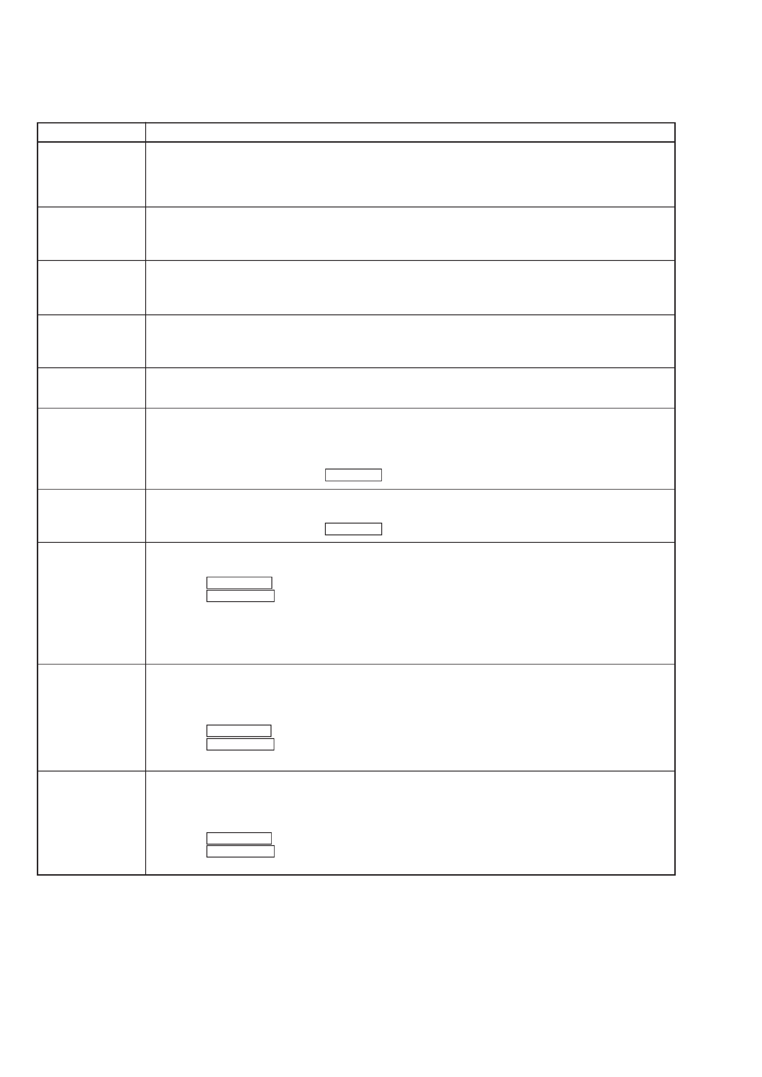
ITEMS OF ERROR HISTORY MODE ITEMS AND CONTENTS
Selecting the Test Mode
Display
op rec tm
op play tm
spdl rp tm
retry err
total err
err history
retry adrs
er refresh
op change
spdl change
History
Displays the total recording time.
When the total recording time is more than 1 minute, displays the hour and minute
When less than 1 minute, displays "Under 1 min"
The display time is the time the laser is set to high power, which is about 1/4 of the actual recording time.
Displays the total playback time.
When the total playback time is more than 1 minute, displays the hour and minute
When less than 1 minute, displays "Under 1 min"
Displays the total rotating time of the spindle motor.
When the total rotating time is more than 1 minute, displays the hour and minute
When less than 1 minute, displays "Under 1 min"
Displays the total number of retry errors during recording and playback
Displays "r xx p yy". xx is the number of errors during recording. yy is the number of errors during playback.
This is displayed in hexadecimal from 00 to FF.
Displays the total number of errors
Displays "total xx". This is displayed in hexadecimal from 00 to FF.
Displays the past ten errors.
Displays "0x ErrCd@@".
X is the history number. The younger the number, the more recent is the history (00 is the latest). @@ is the error
code.
Select the error history number using ./> .
Displays the past five retry addresses.
Displays "xx ADRS yyyy", xx is the history number, yyyy is the cluster with the retry error.
Select the error history number using ./> .
Mode for erasing the error and retry address histories
Procedure
1. Press the REC MODE button when displayed as "er refresh".
2. Press the ENTER/YES button when the display changes to "er refresh?".
When "complete!" is displayed, it means erasure has completed.
Be sure to check the following after executing this mode.
*Data has been erased.
*Perform recording and playback, and check that the mechanism is normal.
Mode for erasing the total time of op rec tm, op play tm.
These histories are based on the time of replacement of the optical pick-up. If the optical pick-up has been
replaced, perform this procedure and erase the history.
Procedure
1. Press the REC MODE button when displayed as "op change".
2. Press the ENTER/YES button when the display changes to "op change?".
When "Complete!" is displayed, it means erasure has completed.
Mode for erasing the total spdl rp tm time
These histories are based on the time of replacement of the spindle motor. If the spindle motor has been replaced,
perform this procedure and erase the history.
Procedure
1. Press the REC MODE button when displayed as "spdl change"
2. Press the ENTER/YES button when the display changes to "spdl change?"
When "Complete!" is displayed, it means erasure has completed.
5
HCD-CL5MD
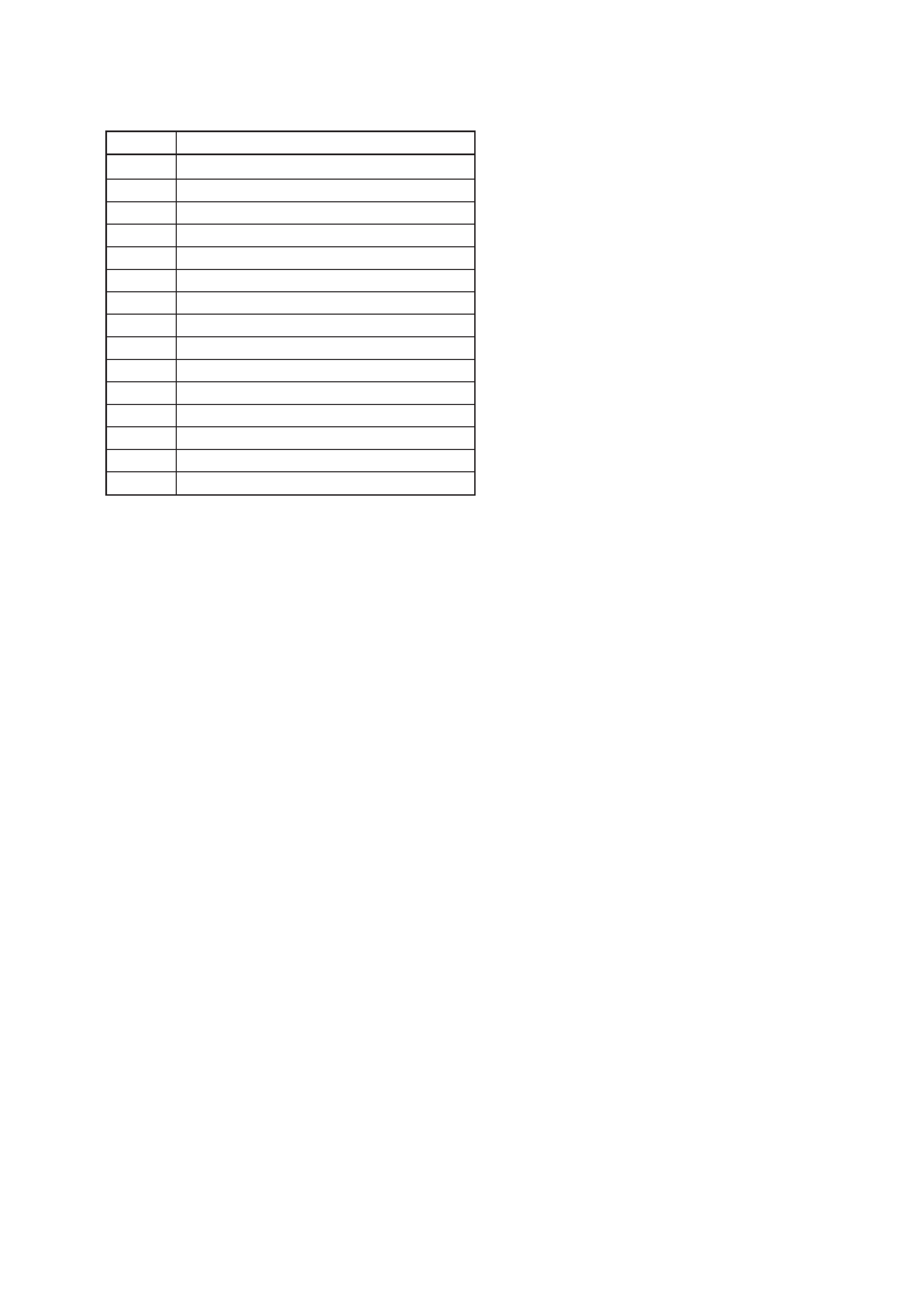
Description
Table of Error Codes
Error Code
10
12
20
21
22
23
24
30
31
40
41
42
43
50
51
Could not load
Loading switches combined incorrectly
Timed out without reading the top of PTOC
Could read top of PTOC, but detected error
Timed out without accessing UTOC
Timed out without reading UTOC
Error in UTOC
Could not start playback
Error in sector
Retry cause generated during normal recording
Retried in DRAM overflow
Retry occurred during TOC writing
Retry aborted during S.F editing
Other than access processing, and could not read address.
Focus NG occurred and overran.