GV-A500/A500E
US Model
Canadian Model
GV-A500
AEP Model
UK Model
E Model
Hong Kong Model
GV-A500E
SERVICE MANUAL
VIDEO CASSETTE RECORDER
MICROFILM
B MECHANISM
Photo : GV-A500E
SPECIFICATIONS
GV-A500 (NTSC)
GV-A500E (PAL)
For MECHANISM ADJUSTMENT, refer to
the "8mm Video MECHANICAL
ADJUSTMENT MANUAL
" (9-973-801-11).

-- 2 --
SAFETY-RELATED COMPONENT WARNING!!
COMPONENTS IDENTIFIED BY MARK
! OR DOTTED LINE WITH
MARK
! ON THE SCHEMATIC DIAGRAMS AND IN THE PARTS
LIST ARE CRITICAL TO SAFE OPERATION. REPLACE THESE
COMPONENTS WITH SONY PARTS WHOSE PART NUMBERS
APPEAR AS SHOWN IN THIS MANUAL OR IN SUPPLEMENTS
PUBLISHED BY SONY.
ATTENTION AU COMPOSANT AYANT RAPPORT
À LA SÉCURITÉ!
LES COMPOSANTS IDENTIFÉS PAR UNE MARQUE
! SUR LES
DIAGRAMMES SCHÉMATIQUES ET LA LISTE DES PIÈCES SONT
CRITIQUES POUR LA SÉCURITÉ DE FONCTIONNEMENT. NE
REMPLACER CES COMPOSANTS QUE PAR DES PIÈSES SONY
DONT LES NUMÉROS SONT DONNÉS DANS CE MANUEL OU
DANS LES SUPPÉMENTS PUBLIÉS PAR SONY.
1.
Check the area of your repair for unsoldered or poorly-soldered
connections. Check the entire board surface for solder splashes
and bridges.
2.
Check the interboard wiring to ensure that no wires are
"pinched" or contact high-wattage resistors.
3.
Look for unauthorized replacement parts, particularly
transistors, that were installed during a previous repair. Point
them out to the customer and recommend their replacement.
4.
Look for parts which, through functioning, show obvious signs
of deterioration. Point them out to the customer and
recommend their replace-ment.
5.
Check the B+ voltage to see it is at the values specified.
6.
Flexible Circuit Board Repairing
· Keep the temperature of the soldering iron around 270°C
during repairing.
· Do not touch the soldering iron on the same conductor of the
circuit board (within 3 times).
· Be careful not to apply force on the conductor when soldering
or unsoldering.
SAFETY CHECK-OUT
After correcting the original service problem, perform the following
safety checks before releasing the set to the customer.

-- 3 --
TABLE OF CONTENTS
SELF-DIAGNOSIS FUNCTION
1.
Self-diagnosis Function ················································ 5
2.
Self-diagnosis display ··················································· 5
3.
Service Mode Display ·················································· 5
3-1.
Display Method ···························································· 5
3-2.
Switching of Backup No. ············································· 5
3-3.
End of Display ······························································ 5
4.
Self-diagnosis Code Table ············································ 6
1.
GENERAL
Before you begin
Using this manual ······························································· 1-1
Checking supplied accessories ··········································· 1-1
Basic operations
Installing the AC power adaptor ········································· 1-1
Inserting a cassette ······························································ 1-1
Playing back a tape ····························································· 1-2
Advanced operations
Watching on a TV screen ···················································· 1-3
Editing onto another tape ···················································· 1-4
Recording from a VCR or TV ············································ 1-4
Changing the mode settings ················································ 1-5
Using alternative power sources ········································· 1-6
Additional information
Charging the vanadiumlithium battery in the VCR ············ 1-7
Usable cassettes and playback modes ································· 1-7
Notes on "InfoLITHIUM" battery pack ····························· 1-7
Maintenance information and precautions ·························· 1-8
Using your VCR abroad ····················································· 1-9
Trouble check ········································································· 1-9
Self-diagnosis display ····························································· 1-10
Identifying the parts ································································ 1-10
Warning indicators ·································································· 1-11
2.
DISASSEMBLY
2-1.
CASSETTE LID ASSEMBLY ····································· 2-1
2-2.
LCD CABINET ···························································· 2-1
2-3.
CRYSTAL INDICATION MODULE,
FLUORESCENT COLD CATHODE TUBE,
PD-88 BOARD ····························································· 2-2
2-4.
CABINET (BOTTOM) ASSEMBLY ··························· 2-3
2-5.
MD BLOCK ASSEMBLY ··········································· 2-3
2-6.
CONTROL (FK-71) SWITCH BLOCK,
DD-100 BOARD ·························································· 2-3
2-7.
VC-197 BOARD ·························································· 2-4
2-8.
B MECHANISM DECK ·············································· 2-4
2-9.
CABINET (R) BLOCK ASSEMBLY,
FP-571 BOARD ··························································· 2-4
2-10. EX-34 BOARD ···························································· 2-4
2-11. IO-62, IR-29, FP-572, FP-573, FP-574,
FP-575 BOARDS SPEAKER ······································ 2-5
2-12. CABINET (UPPER) ASSEMBLY ······························· 2-5
2-13. CIRCUIT BOARDS LOCATION ································ 2-6
3.
BLOCK DIAGRAMS
3-1.
OVERALL BLOCK DIAGRAM ································· 3-1
3-2.
VIDEO BLOCK DIAGRAM 1 ···································· 3-4
3-3.
VIDEO BLOCK DIAGRAM 2 ···································· 3-7
3-4.
SERVO BLOCK DIAGRAM ······································· 3-10
3-5.
SYSTEM CONTROL BLOCK DIAGRAM ················ 3-13
3-6.
AUDIO BLOCK DIAGRAM ······································· 3-15
3-7.
MODE CONTROL BLOCK DIAGRAM ···················· 3-17
3-8.
LCD BLOCK DIAGRAM ··········································· 3-20
3-9.
POWER SUPPLY BLOCK DIAGRAM ······················ 3-23
4.
PRINTED WIRING BOARDS AND
SCHEMATIC DIAGRAMS
4-1.
FRAME SCHEMATIC DIAGRAM ····························· 4-1
4-2.
PRINTED WIRING BOARDS AND
SCHEMATIC DIAGRAMS ········································· 4-4
· VC-197 (MAIN) PRINTED WIRING BOARD ······· 4-5
· VC-197 (REC/PB HEAD AMP)
SCHEMATIC DIAGRAM ··························· 4-11
· VC-197 (EVR) SCHEMATIC DIAGRAM ··············· 4-16
· VC-197 (VIDEO PROCESS)
SCHEMATIC DIAGRAM ··························· 4-19
· VC-197 (Y/C PROCESS)
SCHEMATIC DIAGRAM ··························· 4-23
· VC-197 (TBC/CNR) SCHEMATIC DIAGRAM ······ 4-27
· VC-197 (VIDEO IN/OUT)
SCHEMATIC DIAGRAM ··························· 4-30
· VC-197 (RGB DECODER)
SCHEMATIC DIAGRAM ··························· 4-33
· VC-197 (IR DRIVER), IR-29 (TRANSMITTER)
SCHEMATIC DIAGRAM ··························· 4-37
· IR-29 (TRANSMITTER)
PRINTED WIRING BOARD ······················ 4-40
· VC-197 (SERVO/SYSTEM CONTROL)
SCHEMATIC DIAGRAM ··························· 4-41
· VC-197 (SERVO) SCHEMATIC DIAGRAM ·········· 4-44
· VC-197 (MODE CONTROL)
SCHEMATIC DIAGRAM ··························· 4-47
· VC-197 (AUDIO) SCHEMATIC DIAGRAM ·········· 4-51
· IO-62 (AV IN/OUT) SCHEMATIC DIAGRAM ······ 4-55
· EX-34 (MULTI CONNECTOR)
SCHEMATIC DIAGRAM ··························· 4-59
· EX-34 (MULTI CONNECTOR)
PRINTED WIRING BOARD ······················ 4-63
· IO-62 (AV IN/OUT) PRINTED WIRING BOARD · 4-65
· PD-88 (LCD DRIVER)
SCHEMATIC DIAGRAM ··························· 4-68
· PD-88 (LCD DRIVER)
PRINTED WIRING BOARD ······················ 4-71
· DD-100 (POWER SUPPLY)
PRINTED WIRING BOARD ······················ 4-73
· DD-100 (POWER SUPPLY)
SCHEMATIC DIAGRAM ··························· 4-75
5.
ADJUSTMENT
5-1.
PREPARATIONS ························································· 5-1
1-1.
PREPARATIONS BEFORE ADJUSTMENT ·············· 5-1
1-1-1. List of Service Tools ····················································· 5-1
1-1-2. Adjusting Remote Commander ···································· 5-2
1.
Using the adjusting remote commander ······················· 5-2
2.
Precautions upon using the adjusting
remote commander ······················································· 5-2
1-1-3. Page D Address ···························································· 5-3
1-1-4. Page F Address ····························································· 5-4
1-1-5. Page E Address ····························································· 5-7
1-2.
INITIALIZATION OF D, E, F PAGE DATA ··············· 5-8
1.
Initialization of D, E, F Page Data ······························· 5-8
2.
Modification of D Page Data ········································ 5-8
3.
Modification of F Page Data ········································ 5-9
4.
Modification of E Page Data ········································ 5-10
1-3.
Data Processing ···························································· 5-10
5-2.
MECHANICAL SECTION ADJUSTMENT ·············· 5-11
2-1.
OPERATING WITHOUT A CASSETTE ···················· 5-11
2-2.
TAPE PATH ADJUSTMENT ······································· 5-11
1.
Preparations for adjustments ········································ 5-11

-- 4 --
5-3.
VIDEO SECTION ADJUSTMENTS ·························· 5-12
3-1.
PREPARATIONS BEFORE ADJUSTMENT ·············· 5-12
3-1-1. Equipments to be Used ················································· 5-12
3-1-2. Precautions in Adjustment ············································ 5-13
3-1-3. Connector for Adjustments ··········································· 5-13
3-1-4. Connecting the Equipments ·········································· 5-14
3-1-5. Checking the Input Signals ··········································· 5-15
1.
S VIDEO input ····························································· 5-15
2.
VIDEO input ································································ 5-15
3-1-6. Alignment Tape ···························································· 5-16
3-1-7. Input/Output Level and Impedance ······························ 5-18
3-1-8. Recording Mode (Standard 8/Hi8) switching ·············· 5-18
3-1-9. Service Mode ································································ 5-18
1.
Test mode setting ·························································· 5-18
2.
Emergency Memory Address ······································· 5-19
2-1.
EMG CODE (Emergency Code) ·································· 5-19
2-2.
MSW Codes ································································· 5-20
3.
Bit value discrimination ··············································· 5-21
4.
Input/output selection check ········································· 5-21
5.
Condensation, head clogging check ····························· 5-22
6.
VTR state check (1) ······················································ 5-22
7.
VTR state check (2) ······················································ 5-22
8.
VTR state check (3) ······················································ 5-23
9.
Record of Use Check ···················································· 5-23
3-2.
SYSTEM CONTROL SYSTEM ADJUSTMENTS ···· 5-24
1.
Initialization of D, E, F Page Data ······························· 5-24
2.
Battery End Adjustment (VC-197 board) ····················· 5-24
3.
Battery down voltage check ········································· 5-24
3-3.
SERVO SYSTEM ADJUSTMENTS ··························· 5-25
1.
CAP FG Offset Adjustment (VC-197 board) ··············· 5-25
2.
Switching Position Adjustment (VC-197 board) ·········· 5-25
3.
NTSC LP mode Switching Position Adjustment
(VC-197 board) ···························································· 5-26
3-4.
VIDEO SYSTEM ADJUSTMENTS ···························· 5-26
1.
28 MHz Origin Oscillation Adjustment
(VC-197 board) ···························································· 5-26
2.
Filter f0 Adjustment (VC-197 board) ··························· 5-27
3.
Y OUT Level Adjustment (VC-197 board) ·················· 5-27
4.
C OUT Level Adjustment (VC-197 board) ·················· 5-28
5.
RP Filter f0 Adjustment (VC-197 board) ····················· 5-28
6.
AFC f0 Adjustment (VC-197 board) ···························· 5-29
7.
NTSC Hi8 REC Y Current Adjustment
(VC-197 board) ···························································· 5-30
8.
PAL Hi8 REC Y Current Adjustment
(VC-197 board) ···························································· 5-30
9.
NTSC Hi8 REC C Current Adjustment
(VC-197 board) ···························································· 5-31
10.
PAL Hi8 REC C Current Adjustment
(VC-197 board) ···························································· 5-32
11.
REC C Current Adjustment
(VC-197 board) ···························································· 5-33
3-5.
IR Transmitter Adjustments ·········································· 5-34
1.
IR Video Carrier Frequency Adjustment
(MI-27/28 board) ·························································· 5-34
2.
IR Video Deviation Adjustment (MI-27/28 board) ······ 5-34
3.
IR Audio Deviation Adjustment (MI-27/28 board) ······ 5-35
3-6.
AUDIO SYSTEM ADJUSTMENT ······························ 5-36
1.
1.5 MHz Deviation Adjustment (VC-197 board) ········· 5-37
2.
1.7 MHz Deviation Adjustment (VC-197 board) ········· 5-37
3.
BPF f0 Adjustment (VC-197 board) ···························· 5-38
3-7.
LCD SYSTEM ADJUSTMENT ·································· 5-39
1.
LCD Initial Data Input ················································· 5-39
2.
VCO Adjustment (PD-88 baord) ·································· 5-40
3.
H POS Adjustment (VC-197 baord) ····························· 5-40
4.
Bright Adjustment (VC-197 baord) ······························ 5-41
5.
Contrast Adjustment (VC-197 baord) ·························· 5-41
6.
Color Adjustment for NTSC model (VC-197 baord) ··· 5-42
7.
Hue Adjustment for NTSC model (VC-197 baord) ···· 5-42
8.
Burst Cleaning Adjustment for PAL model
(VC-197 baord) ···························································· 5-43
9.
Color Adjustment for PAL model (VC-197 baord) ······ 5-43
10.
V-COM Adjustment (PD-88 baord) ····························· 5-44
11.
White Balance Adjustment (VC-197 baord) ················ 5-44
6.
REPAIR PARTS LIST
6-1.
EXPLODED VIEWS ··················································· 6-1
6-1-1. OUTER CABINET ASSEMBLY ································· 6-1
6-1-2. LCD BLOCK, UPPER CABINET
BLOCK ASSEMBLY ··················································· 6-2
6-1-3. MD BLOCK ASSEMBLY ··········································· 6-3
6-1-4. CASSETTE COMPARTMENT BLOCK SECTION ··· 6-4
6-1-5. LS CHASSIS BLOCK SECTION ······························· 6-5
6-1-6. MECHANISM CHASSIS BLOCK SECTION ············ 6-6
6-2.
ELECTRICAL PARTS LIST ······································· 6-7
-- 5 --
SELF-DIAGNOSIS FUNCTION
1. Self-diagnosis Function
When problems occur while the unit is operating, the self-diagnosis
function starts working, and displays on the LCD window what to
do. This function consists of two display; self-diagnosis display and
service mode display.
Details of the self-diagnosis functions are provided in the Instruction
manual.
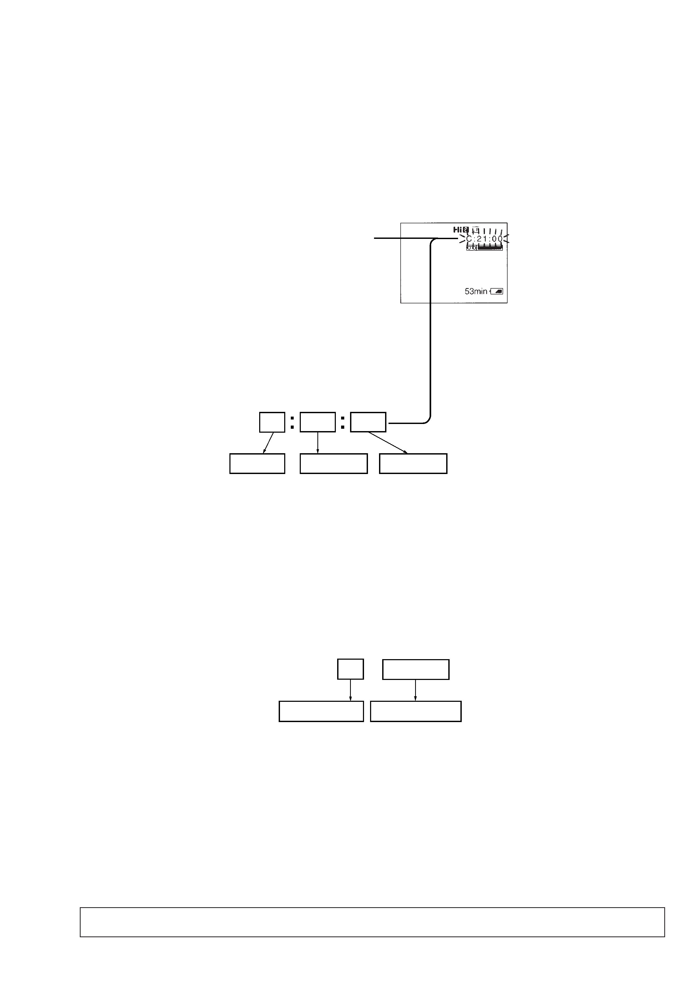
2. Self-diagnosis display
When problems occur while the unit is operating, the counter of the
LCD window shows a 4-digit display consisting of an alphabet and
numbers, which blinks at 3.2 Hz. This 5-character display indicates
the "repaired by:", "block" in which the problem occurred, and
"detailed code" of the problem.
3. Service Mode Display
The service mode display shows up to six self-diagnosis codes shown in the past.
3-1. Display Method
While pressing the "STOP" key, set the power switch from OFF to "ON", and continue pressing the "STOP" key for 5 seconds continuously.
The service mode will be displayed, and the counter will show the backup No. and the 5-character self-diagnosis codes.
3-2. Switching of Backup No.
By rotating the SEL/PUSH EXEC dial, past self-diagnosis codes will be shown in order. The backup No. in the [] indicates the order in which
the problem occurred. (If the number of problems which occurred is less than 6, only the number of problems which occurred will be shown.)
[1] : Occurred first time
[4] : Occurred fourth time
[2] : Occurred second time
[5] : Occurred fifth time
[3] : Occurred third time
[6] : Occurred the last time
3-3. End of Display
Turning OFF the power supply will end the service mode display.
1 1
3 1
C
Repaired by:
Refer to page 7, 8
Self-diagnosis Code Table.
C : Corrected by customer
Indicates the appropriate
H : Corrected by dealer
step to be taken.
E : Corrected by service
E.g.
engineer
31 ....Reload the tape.
32 ....Turn on power again.
Block
Detailed Code
Blinks at 3.2Hz
LCD screen
Backup No.
self-diagnosis codes
C : 3 1 : 1 1
[3]
Order of previous errors
Note: The self-diagnosis display data will be backed up by the coin-type lithium battery. When this coin-type lithium battery is
disconnected, the self-diagnosis data will be lost by initialization.