4-077-465-12 (1)
© 2000 Sony Corporation
Trinitron Color
Graphic Display
®
Operating Instructions
Mode d'emploi
Bedienungsanleitung
Manual de instrucciones
Istruzioni per l'uso
Gebruiksaanwijzing
Bruksanvisning
GB
FR
DE
ES
IT
SE
NL
GDM-FW900
2
Owner's Record
The model and serial numbers are located at the rear of the unit.
Record these numbers in the spaces provided below. Refer to them
whenever you call upon your dealer regarding this product.
Model No.
Serial No.
To prevent fire or shock hazard, do not expose the
unit to rain or moisture.
Dangerously high voltages are present inside the
unit. Do not open the cabinet. Refer servicing to
qualified personnel only.
FCC Notice
This equipment has been tested and found to comply with the limits
for a Class B digital device, pursuant to Part 15 of the FCC Rules.
These limits are designed to provide reasonable protection against
harmful interference in a residential installation. This equipment
generates, uses, and can radiate radio frequency energy and, if not
installed and used in accordance with the instructions, may cause
harmful interference to radio communications. However, there is no
guarantee that interference will not occur in a particular installation.
If this equipment does cause harmful interference to radio or
television reception, which can be determined by turning the
equipment off and on, the user is encouraged to try to correct the
interference by one or more of the following measures:
Reorient or relocate the receiving antenna.
Increase the separation between the equipment and receiver.
Connect the equipment into an outlet on a circuit different from
that to which the receiver is connected.
Consult the dealer or an experienced radio/TV technician for help.
You are cautioned that any changes or modifications not expressly
approved in this manual could void your authority to operate this
equipment.
INFORMATION
This product complies with Swedish National Council for Metrology
(MPR) standards issued in December 1990 (MPR II) for very low
frequency (VLF) and extremely low frequency (ELF).
INFORMATION
Ce produit est conforme aux normes du Swedish National Council
for Metrology de décembre 1990 (MPR II) en ce qui concerne les
fréquences très basses (VLF) et extrêmement basses (ELF).
INFORMACIÓN
Este producto cumple las normas del Consejo Nacional Sueco para
Metrología (MPR) emitidas en diciembre de 1990 (MPR II) para
frecuencias muy bajas (VLF) y frecuencias extremadamente bajas (ELF).
If you have any questions about this product, you may call:
Sony Customer Information Center
1-800-222-SONY (7669)
or write to:
Sony Customer Information Center
1 Sony Drive, Mail Drop #T1-11, Park Ridge, NJ 07656
WARNING
NOTICE
This notice is applicable for USA/Canada only.
If shipped to USA/Canada, install only a UL LISTED/CSA
LABELLED power supply cord meeting the following
specifications:
SPECIFICATIONS
Plug Type
Nema-Plug 5-15p
Cord
Type SVT or SJT, minimum 3
× 18 AWG
Length
Maximum 15 feet
Rating
Minimum 7 A, 125 V
NOTICE
Cette notice s'applique aux Etats-Unis et au Canada
uniquement.
Si cet appareil est export* aux Etats-Unis ou au Canada, utiliser
le cordon d'alimentation portant la mention UL LISTED/CSA
LABELLED et remplissant les conditions suivantes:
SPECIFICATIONS
Type de fiche
Fiche Nema 5-15 broches
Cordon
Type SVT ou SJT, minimum 3
× 18 AWG
Longueur
Maximum 15 pieds
Tension
Minimum 7 A, 125 V
As an
ENERGY STAR Partner, Sony
Corporation has determined that this
product meets the
ENERGY STAR
guidelines for energy efficiency.
This monitor complies with the
TCO'99 guidelines.
Declaration of Conformity
Trade Name:
SONY
Model No.:
GDM-FW900
Responsible Party:
Sony Electronics Inc.
Address:
1 Sony Drive, Park Ridge, NJ 07656 USA
Telephone No.:
201-930-6972
This device complies with Part 15 of the FCC Rules. Operation is
subject to the following two conditions: (1) This device may not
cause harmful interference, and (2) this device must accept any
interference received, including interference that may cause
undesired operation.
3
Table of Contents
·Trinitronâ is a registered trademark of
Sony Corporation.
· Macintosh is a trademark licensed to
Apple Computer, Inc., registered in the
U.S.A. and other countries.
· Windowsâ and MS-DOS are registered
trademarks of Microsoft Corporation in
the United States and other countries.
· IBM PC/AT and VGA are registered
trademarks of IBM Corporation of the
U.S.A.
· VESA and DDCä are trademarks of the
Video Electronics Standard
Association.
·
ENERGY STAR is a U.S. registered
mark.
· All other product names mentioned
herein may be the trademarks or
registered trademarks of their respective
companies.
·Furthermore, "
ä" and "â" are not
mentioned in each case in this manual.
GB
Precautions. . . . . . . . . . . . . . . . . . . . . . . . . . . . . . . . . . . . . . . . . . . . 4
Identifying parts and controls . . . . . . . . . . . . . . . . . . . . . . . . . . . . . . 5
Setup . . . . . . . . . . . . . . . . . . . . . . . . . . . . . . . . . . . . . . . . . .6
Step 1: Connect your monitor to your computer . . . . . . . . . . . . . . . 6
Step 2: Connect the power cord. . . . . . . . . . . . . . . . . . . . . . . . . . . . 7
Step 3: Turn on the monitor and computer . . . . . . . . . . . . . . . . . . . 7
Connecting Universal Serial Bus (USB) compliant peripherals . . . . 8
Selecting the on-screen menu language (LANG) . . . . . . . . . . . . . . . 8
Selecting the input signal . . . . . . . . . . . . . . . . . . . . . . . . . . . . . . . . . 9
Automatically sizing and centering the picture (AUTO) . . . . . . . . . . 9
Customizing Your Monitor . . . . . . . . . . . . . . . . . . . . . . .10
Navigating the menu . . . . . . . . . . . . . . . . . . . . . . . . . . . . . . . . . . . . 10
Adjusting the brightness and contrast. . . . . . . . . . . . . . . . . . . . . . . 11
Adjusting the centering of the picture (CENTER) . . . . . . . . . . . . . . 12
Adjusting the size of the picture (SIZE) . . . . . . . . . . . . . . . . . . . . . 12
Enlarging or reducing the picture (ZOOM) . . . . . . . . . . . . . . . . . . . 12
Adjusting the shape of the picture (GEOM) . . . . . . . . . . . . . . . . . . 12
Adjusting the color of the picture (COLOR) . . . . . . . . . . . . . . . . . . 12
Adjusting the quality of the picture (SCREEN) . . . . . . . . . . . . . . . . 14
Adjusting the convergence (CONV) . . . . . . . . . . . . . . . . . . . . . . . . 15
Additional settings (OPTION) . . . . . . . . . . . . . . . . . . . . . . . . . . . . . 15
Resetting the adjustments . . . . . . . . . . . . . . . . . . . . . . . . . . . . . . . 16
Technical Features . . . . . . . . . . . . . . . . . . . . . . . . . . . . .16
Preset and user modes. . . . . . . . . . . . . . . . . . . . . . . . . . . . . . . . . . 16
Power saving function. . . . . . . . . . . . . . . . . . . . . . . . . . . . . . . . . . . 16
Troubleshooting. . . . . . . . . . . . . . . . . . . . . . . . . . . . . . . .17
If thin lines appear on your screen (damper wires). . . . . . . . . . . . . 17
On-screen messages . . . . . . . . . . . . . . . . . . . . . . . . . . . . . . . . . . . 17
Trouble symptoms and remedies . . . . . . . . . . . . . . . . . . . . . . . . . . 18
Self-diagnosis function . . . . . . . . . . . . . . . . . . . . . . . . . . . . . . . . . . 20
Specifications. . . . . . . . . . . . . . . . . . . . . . . . . . . . . . . . . .20
Appendix. . . . . . . . . . . . . . . . . . . . . . . . . . . . . . . . . . . . . . . i
Preset mode timing table . . . . . . . . . . . . . . . . . . . . . . . . . . . . . . . . . .i
TCO'99 Eco-document . . . . . . . . . . . . . . . . . . . . . . . . . . . . . . . . . . . .i
4
Precautions
Warning on power connections
· Use the supplied power cord. If you use a different power cord,
be sure that it is compatible with your local power supply.
For the customers in the UK
If you use the monitor in the UK, be sure to use the supplied UK
power cable.
For the customers in the U.S.A.
If you do not use the appropriate cord, this monitor will not
conform to mandatory FCC standards.
· Before disconnecting the power cord, wait at least 30 seconds
after turning off the power to allow the static electricity on the
screen's surface to discharge.
· After the power is turned on, the screen is demagnetized
(degaussed) for about 3 seconds. This generates a strong
magnetic field around the screen which may affect data stored
on magnetic tapes and disks placed near the monitor. Be sure to
keep magnetic recording equipment, tapes, and disks away
from the monitor.
Installation
Do not install the monitor in the following places:
· on surfaces (rugs, blankets, etc.) or near materials (curtains,
draperies, etc.) that may block the ventilation holes
· near heat sources such as radiators or air ducts, or in a place
subject to direct sunlight
· in a place subject to severe temperature changes
· in a place subject to mechanical vibration or shock
· on an unstable surface
· near equipment which generates magnetism, such as a
transformer or high voltage power lines
· near or on an electrically charged metal surface
Maintenance
· Clean the screen with a soft cloth. If you use a glass cleaning
liquid, do not use any type of cleaner containing an anti-static
solution or similar additive as this may scratch the screen's
coating.
· Do not rub, touch, or tap the surface of the screen with sharp or
abrasive items such as a ballpoint pen or screwdriver. This type
of contact may result in a scratched picture tube.
· Clean the cabinet, panel and controls with a soft cloth lightly
moistened with a mild detergent solution. Do not use any type
of abrasive pad, scouring powder or solvent, such as alcohol or
benzene.
Transportation
When you transport this monitor for repair or shipment, use the
original carton and packing materials.
Never grasp the control stick when you transport the
monitor.
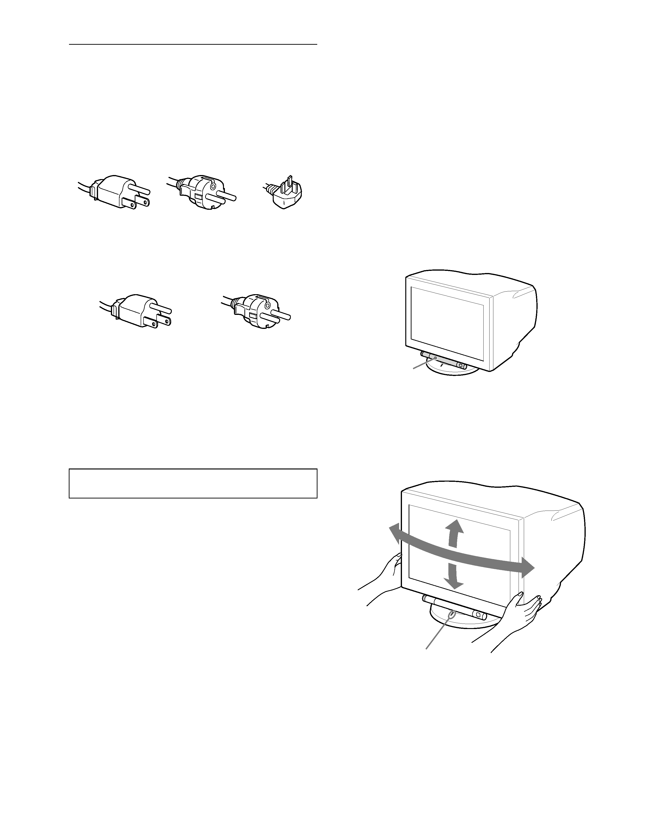
Use of the tilt-swivel
This monitor can be adjusted within the angles shown below. To
find the center of the monitor's turning radius, align the center of
the monitor's screen with the centering dots on the stand.
Hold the monitor at the bottom with both hands when you turn it
horizontally or vertically.
The equipment should be installed near an easily accessible
outlet.
Example of plug types
for 100 to 120 V AC
for 200 to 240 V AC
for 240 V AC only
Example of plug types
for 100 to 120 V AC
for 200 to 240 V AC
Control stick
165°
5°
165°
15°
Centering dots
5
GB
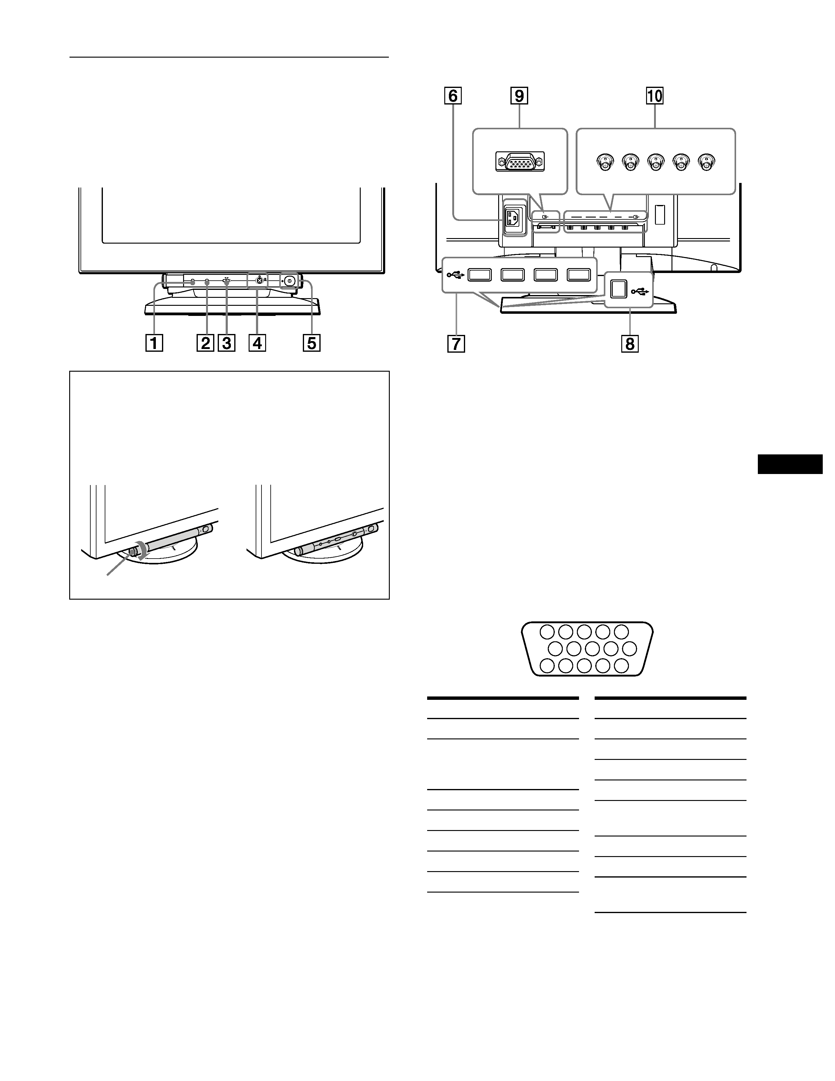
Identifying parts and controls
See the pages in parentheses or further details.
1 RESET (reset) button (page 16)
This button resets the adjustments to the factory settings.
2 ASC (auto sizing and centering) button (page 9)
This button automatically adjusts the size and centering of the
picture.
3 INPUT (input) switch (page 9)
This switch selects the HD15 or BNC video input signal.
4 Joystick (page 11)
The joystick is used to display the menu and make
adjustments to the monitor, including brightness and contrast
adjustments.
5 ! (power) switch and indicator (pages 7, 16, 20)
This button turns the monitor on and off. The power indicator
lights up in green when the monitor is turned on, and either
flashes in green and orange, or lights up in orange when the
monitor is in power saving mode.
6 AC IN connector (page 7)
This connector provides AC power to the monitor.
7 USB (universal serial bus) downstream connectors
(page 8)
Use these connectors to link USB peripheral devices to the
monitor.
8 USB (universal serial bus) upstream connector
(page 8)
Use this connector to link the monitor to a USB compliant
computer.
9 Video input 1 connector (HD15) (page 6)
This connector inputs RGB video signals (0.700 Vp-p,
positive) and sync signals.
* DDC (Display Data Channel) is a standard of VESA.
q; Video input 2 connector (BNC) (page 6)
This connector inputs RGB video signals (0.700 Vp-p,
positive) and sync signals.
To use the control stick
This monitor has a cylindrical swivel control stick. To operate the
controls, turn the knob on the left side downward to expose the control
buttons. When the control buttons are not needed, turn the knob up to
hide the control buttons.
When not using
When using
MENU
INPUT
ASC
RESET
2
1
Front
,
AC IN
RG
B
HD
VD
2
1
Rear
forward side
rear side
forward side
rear side
5 4
3 2 1
6
7
8
9
10
11
12
13
14
15
Pin No.
Signal
1Red
2Green
(Composite Sync
on Green)
3Blue
4
ID (Ground)
5
DDC Ground*
6
Red Ground
7
Green Ground
Pin No.
Signal
8
Blue Ground
9
DDC + 5V*
10
Ground
11
ID (Ground)
12
Bi-Directional
Data (SDA)*
13
H. Sync
14
V. Sync
15
Data Clock
(SCL)*
Knob