SERVICE MANUAL
MODEL
COMMANDER
DEST. CHASSIS NO.
MODEL
COMMANDER
DEST. CHASSIS NO.
MICROFILM
Please file according to model size. .......
FDL-PT222
US
2.2
LCD COLOR TV
2
FDL-PT222
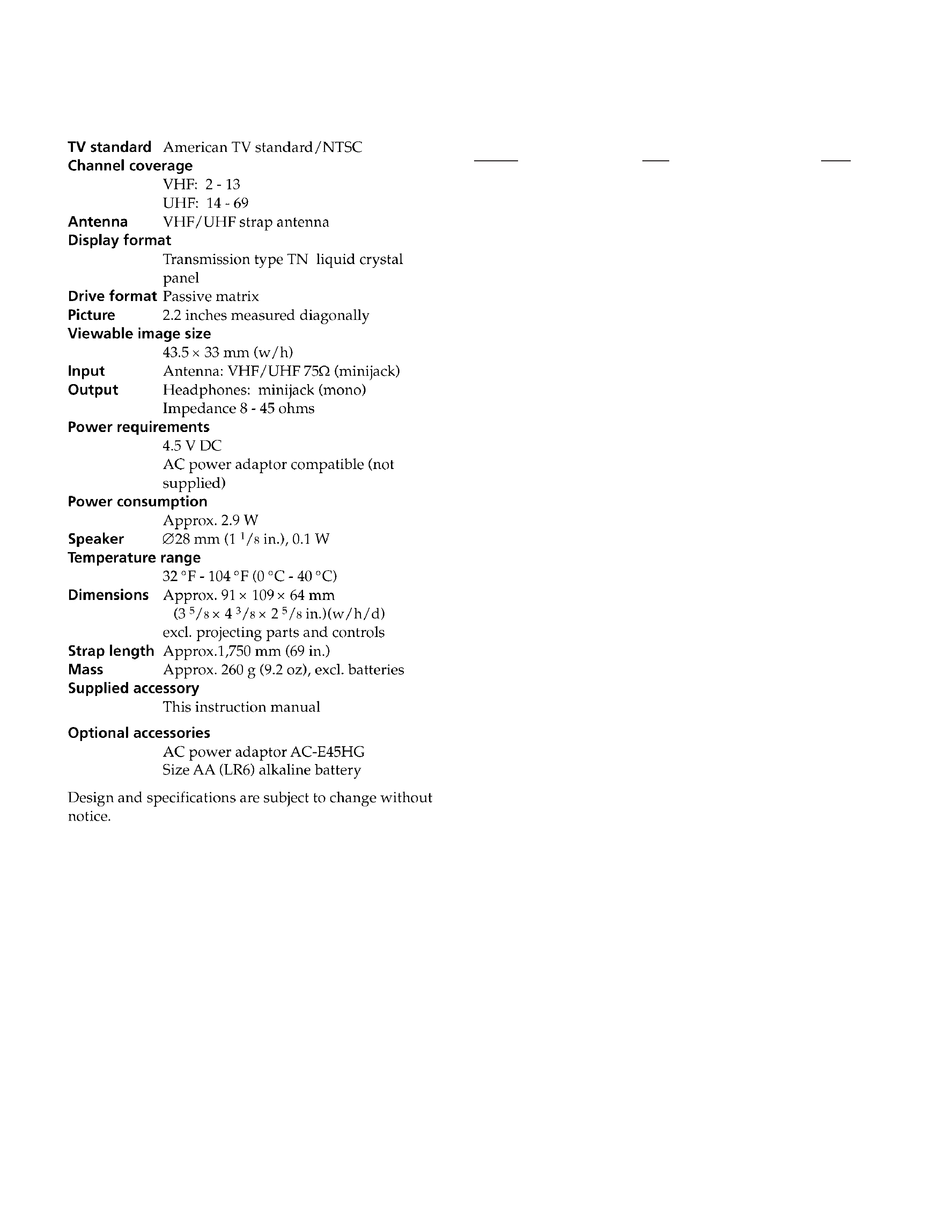
SPECIFICATIONS
TABLE OF CONTENTS
Section
Title
Page
1. GENERAL
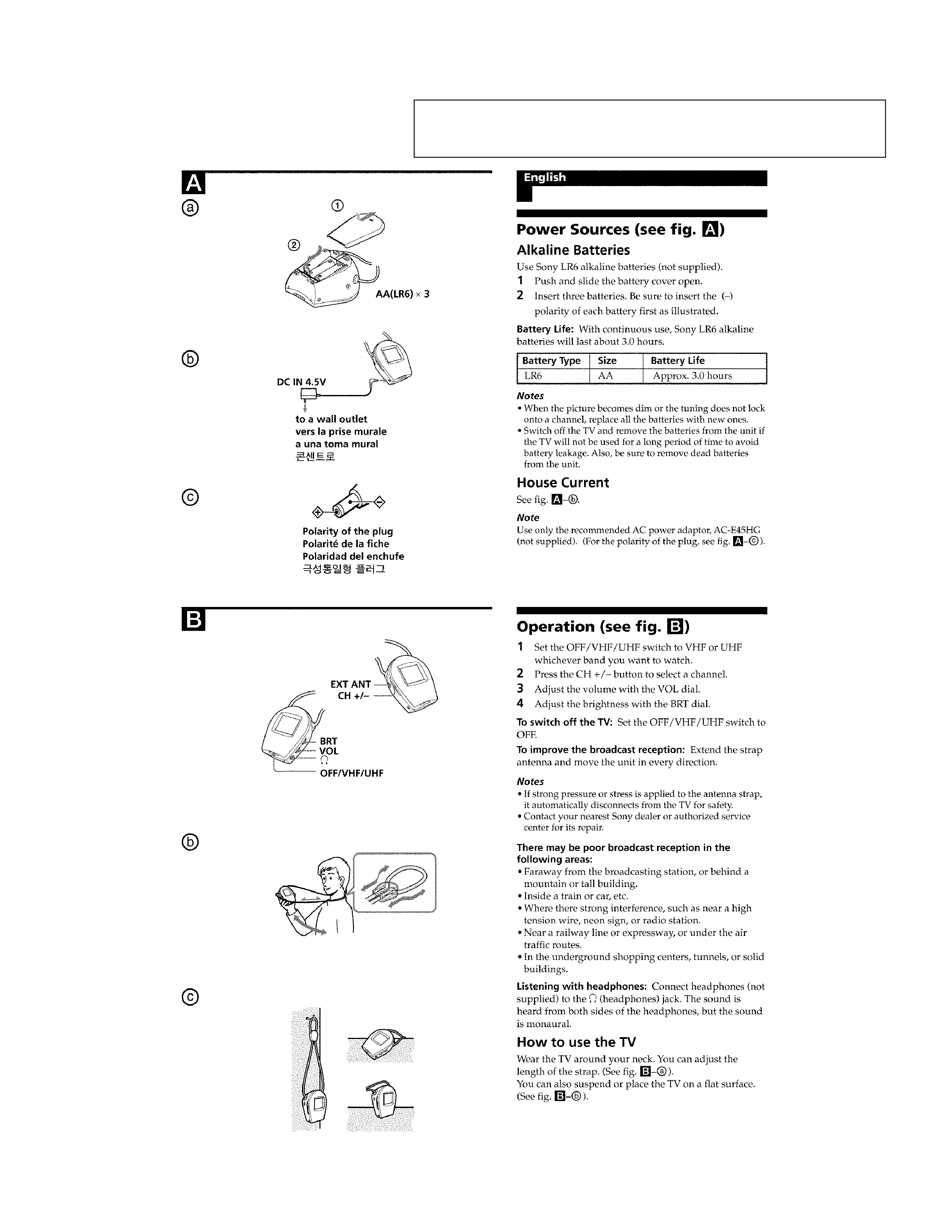
Power Sources (see fig. A) ...................................................... 3
Operation (see fig. B) .............................................................. 3
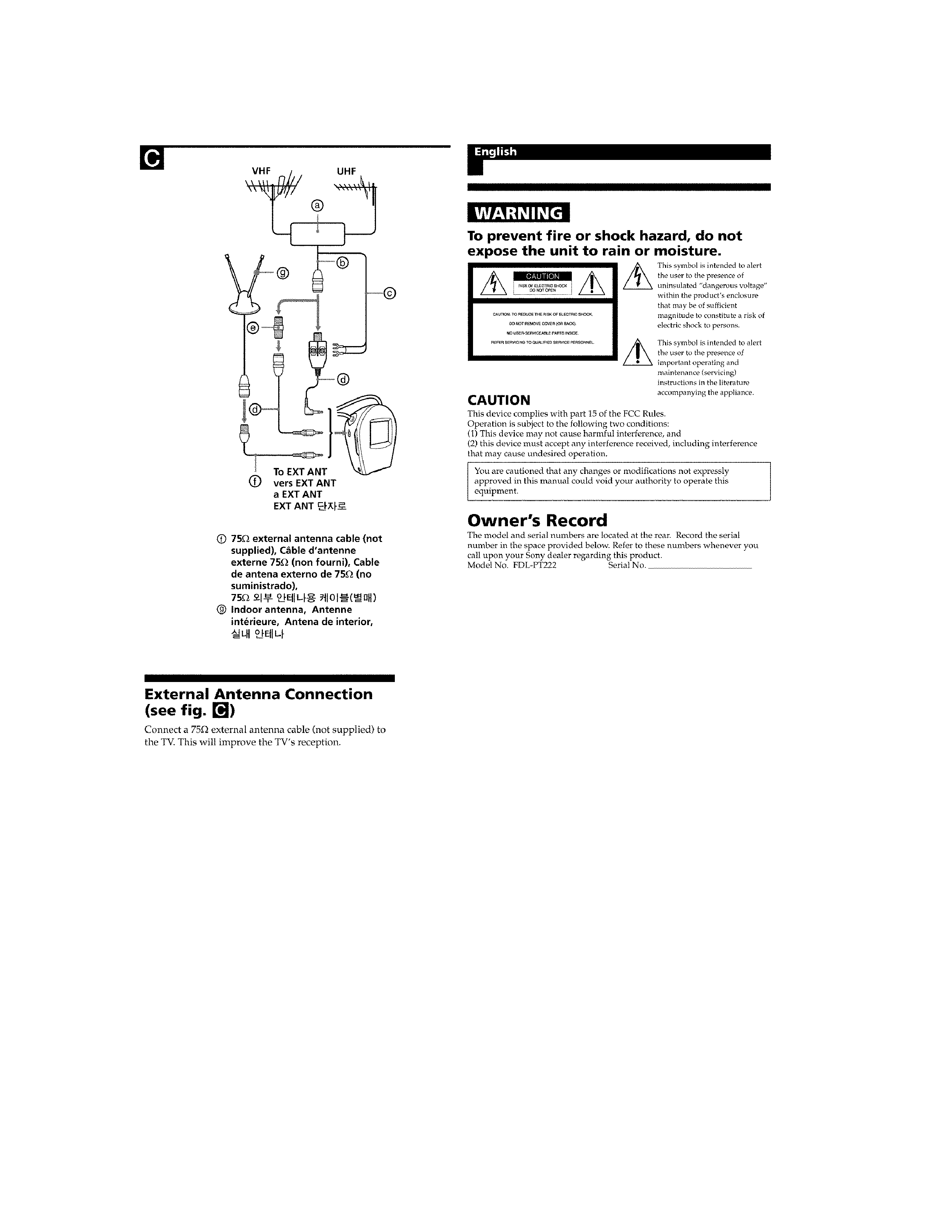
External Antenna Connection (see fig. C) ............................... 4
WARNING .............................................................................. 4
2. DISASSEMBLY
2-1.
Cabinets ........................................................................ 5
2-2.
Service Position ............................................................ 6
3. CIRCUIT ADJUSTMENTS ............................................ 7
4. DIAGRAMS
4-1. Block Diagram (1) ............................................................ 9
4-2. Block Diagram (2) .......................................................... 11
4-3. Circuit Boards Location ................................................. 14
4-4. Printed Wiring Boards and Schematic Diagrams ........... 14
· T1 Board ..................................................................... 15
· A Board ....................................................................... 19
· B Board ....................................................................... 23
4-5. Semiconductors .............................................................. 27
5. EXPLODED VIEWS
5-1. Chassis Section .............................................................. 28
6. ELECTRICAL PARTS LIST ........................................ 29
(CAUTION)
SHORT CIRCUIT THE ANODE OF THE PICTURE TUBE AND THE AN-
ODE CAP TO THE METAL CHASSIS, CRT SHIELD, OR CARBON PAINT-
ED ON THE CRT, AFTER REMOVING THE ANODE.
WARNING!!
AN ISOLATION TRANSFORMER SHOULD BE USED DURING ANY SER-
VICE TO AVOID POSSIBLE SHOCK HAZARD, BECAUSE OF LIVE CHAS-
SIS.
THE CHASSIS OF THIS RECElVER IS DIRECTLY CONNECTED TO THE
AC POWER LINE.
SAFETY-RELATED COMPONENT WARNING!!
COMPONENTS IDENTIFIED BY SHADING AND MARK
! ON THE SCHE-
MATIC DIAGRAMS, EXPLODED VIEWS AND IN THE PARTS LIST ARE
CRITICAL TO SAFE OPERATION. REPLACE THESECOMPONENTS
WITH SONY PARTS WHOSE PART NUMBERS APPEAR AS SHOWN IN
THIS MANUAL OR IN SUPPLEMENTS PUBLISHED BY SONY. CIRCUIT
ADJUSTMENTS THAT ARE CRITICAL TO SAFEOPERATION ARE IDEN-
TIFIED IN THIS MANUAL. FOLLOW THESE PROCEDURES WHENEV-
ER CRITICAL COMPONENTS ARE REPLACED OR IMPROPER OPERA-
TION IS SUSPECTED.
3
SECTION 1
GENERAL
The operating instructions mentioned here are partial abstracts from the
Operating Instructions Manual. The page numbers of the Operating
Instruction Manual remain as in the manual. (Par t no : 4-083-376-11)
4
5
FDL-PT222
SECTION 2
DISASSEMBLY
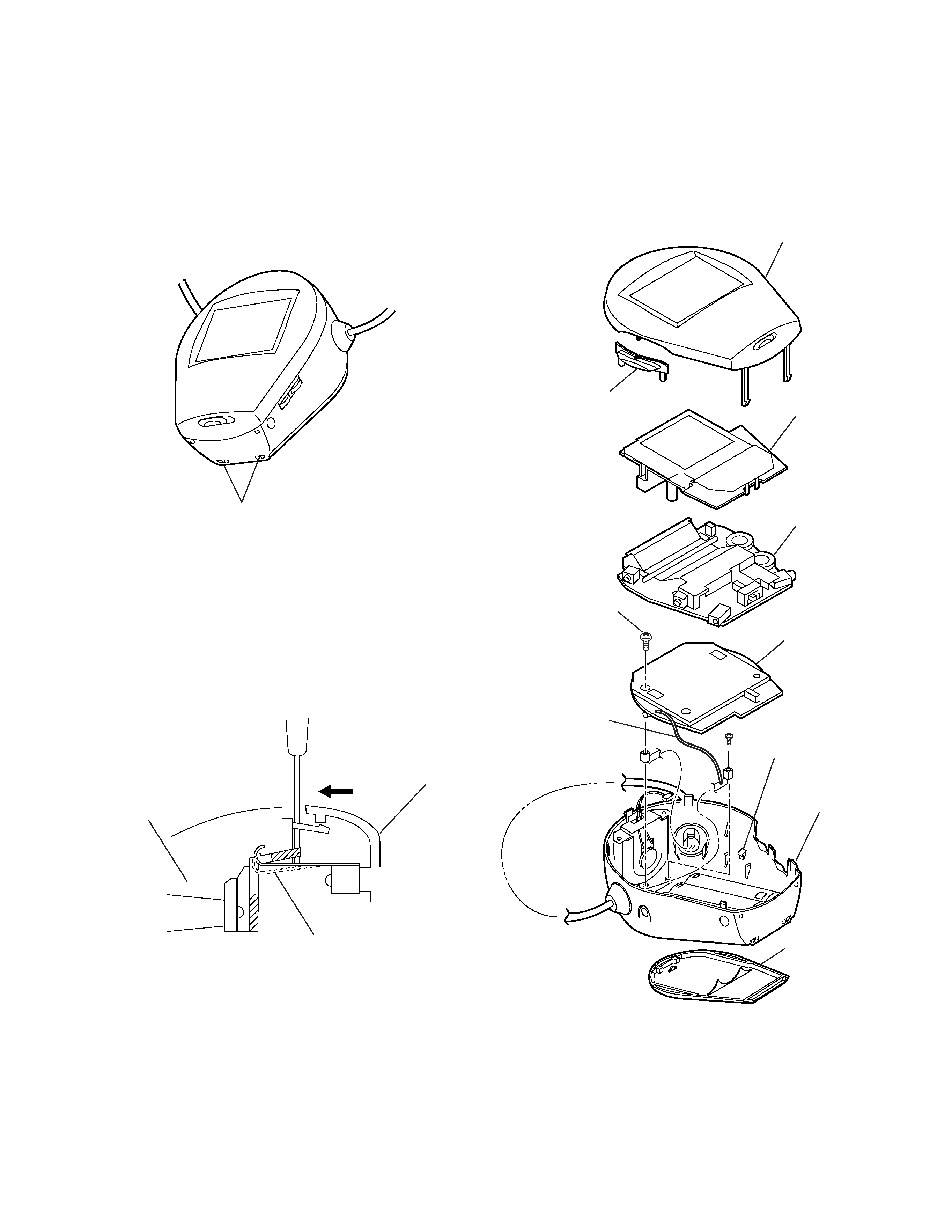
2-1. CABINETS
claw
1. Remove the battery cover 8.
2. Push two claws with a screwdriver or equivalent on the bottom and
remove them.
3. While pushing the rear cabinet, remove claws of joints with
the front cabinet.
4. Insert a screwdriver or equivalent to the gap on the upper side of the
cabinet, and while pushing the lock spring, put it down to the rear cabinet
side.
5. Remove the channel button 2.
6. Disconnect CN501 (for speaker) on the A board.
7. Remove the B board 3 and the A board 4.
8. Remove solder for the lead wire (BLK) 9.
9. Remove a screw (+PTP2X6) 6 secured the T board 5.
10. Release the T1 board 5 from two claws (right and left) on the rear cabinet.
front cabinet
rear cabinet
lock spring
8 battery cover
2 channel button
7 rear cabinet
claw
1 front cabinet
3 B board
5 T1 board
6 screw (+PTP2X6)
4 A board
9 lead wire (BLK)