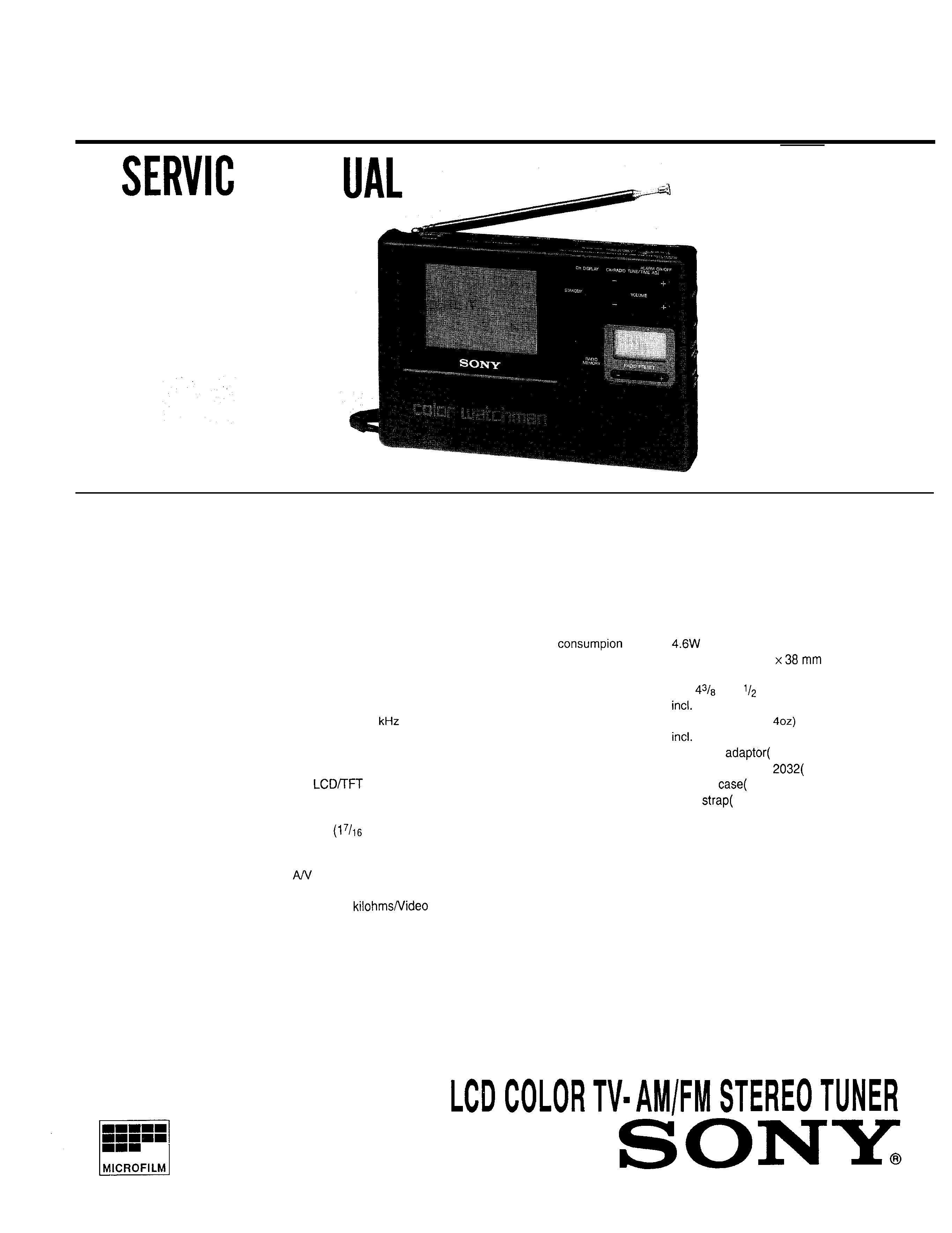
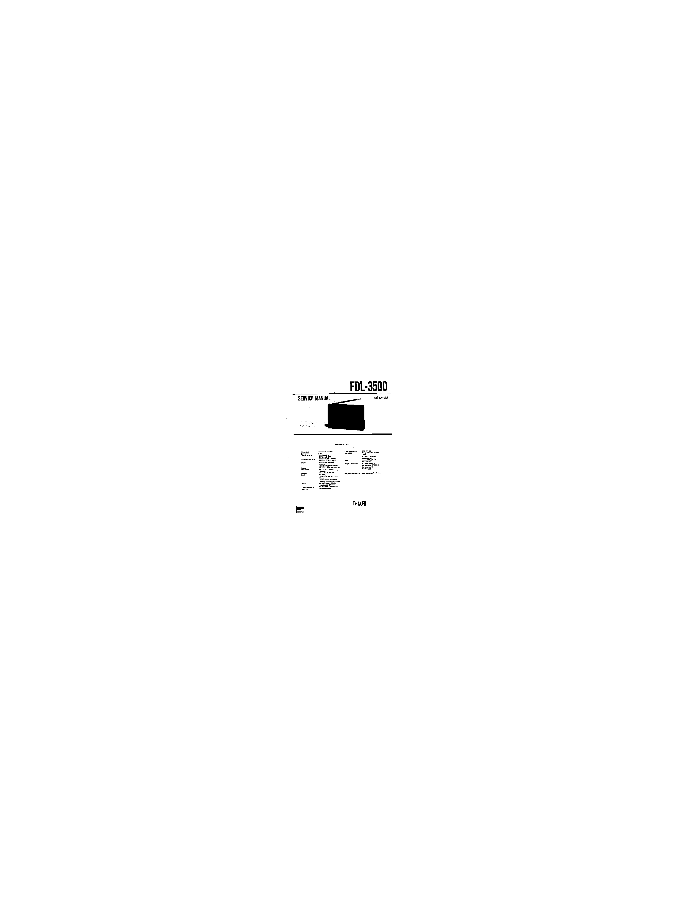
FDL-3500
E MAN
US Model
TV
standard
Color system
Channel
coverage
Radio
frequency
range
Antenna
Display
Picture size
Speaker
Input
output
Power
requirement
Battery life
SPECIFICATIONS
American
TV
standard
NTSC
VHF channels 2-l 3
UHF
channel
14-69
FM:
87.6-108
MHz
(Stereo)
AM: 530-l ,710
(Mono)
VHF/UHF/FM: telescopic
antenna
AM: built-in ferrite bar antenna
TN
active matrix method
3-inch
picture
measured
diagonally
36 mm
inches) dia.
EXT ANT:
minijack, impedance 75 ohms
IN:
tripolar minijack, impedance
Audio 47
75 ohms
PHONES: stereo minijack,
impedance
8-300
ohms
9 V DC, See "Power Sources"
See "Power Soures"
Power
Dimensions
Mass
(9 V DC)
Approx. 175x111
(w/h/d)
(7 x
x `1
inches)
projecting parts
Approx. 570g (1 lb
batteries
AC power
1)
Lithium battery CR
1)
Carrying
1)
Hand
1)
Supplied accessories
Design and specifications subject to change without notice.
LCD COLOR
STEREO TUNER
SONY.
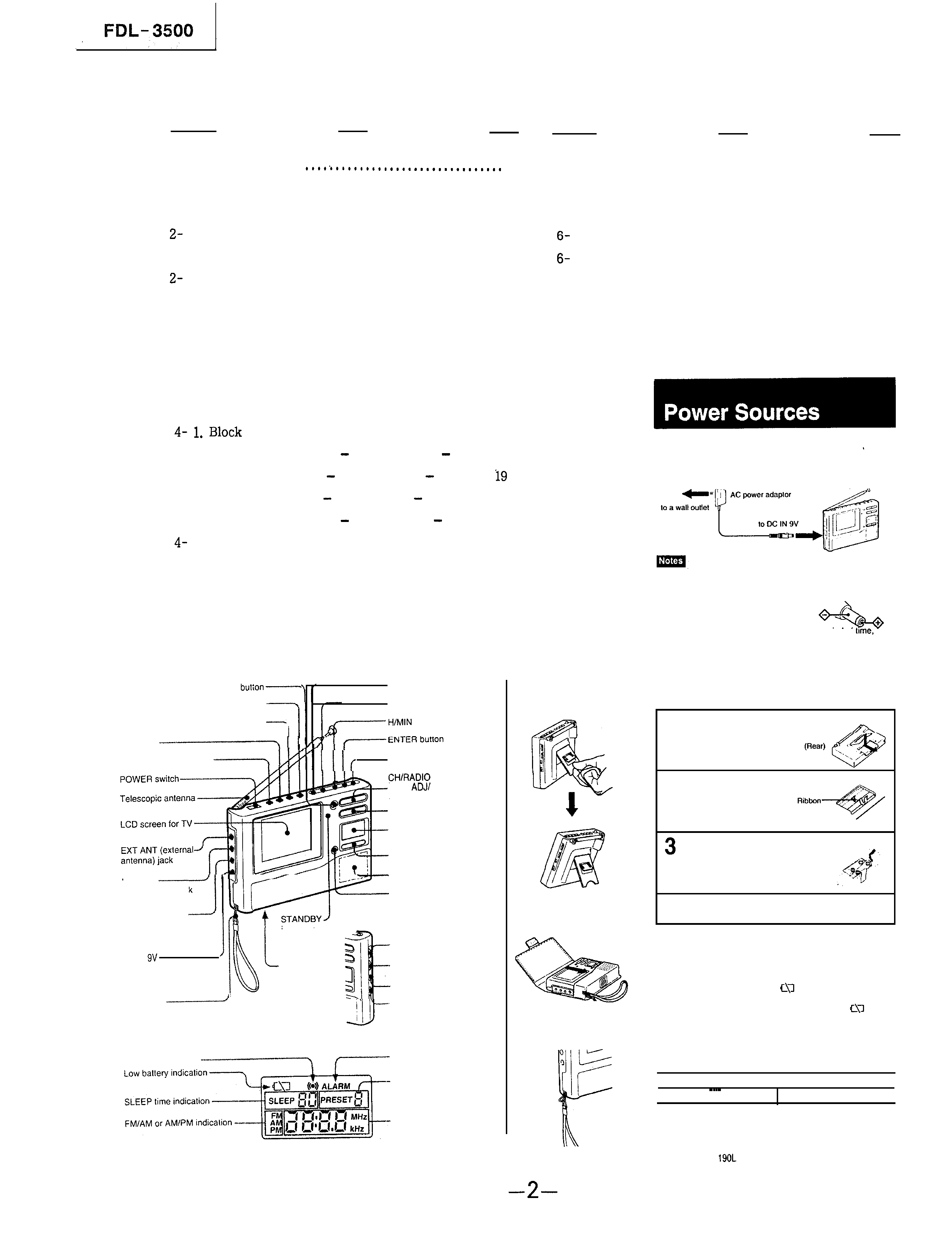
TABLE OF CONTENTS
Section
Title
Page
Section
Title
Page
1. GENERAL . . . . . . . . .
2
5. PIN DESCRIPTION . . . . . . . . . . . . . . . . . . . . . . . . . . . . . . . . . . 37
2. DISASSEMBLY
1. Front and Rearcabinet Assy . . . . . . . . . . . . . . . . . . . 3
6. EXPLODED VIEWS
1. Cabinet Section . . . . . . . . . . . . . . . . . . . . . . . . . . . . . . .
41
2-2. Main and Inverter Board ....................... 3
2. Display Section ............................... 42
3. Sub Board ......................................
4
2-4. Fluorescent Indicator Tube and Indicator
7. ELECTRICAL PARTS LIST ..........................
43
Module ..........................................
4
3. ADJUSTMENTS .....................................
5
4. DIAGRAMS
Diagram . . . . . . . . . . . . . . . . . . . . . . . . . . . . . . . .
12
4-2. Printed Wiring Board
Main Section
. . . . . 15
4-3. Schematic `Diagram
Main Section
. . . . . . . .
4-4. Schematic Diagram
Sub Section
. . . . . . . . . 22
4-5. Printed Wiring Board
Sub Section
. l
. . . . . 25
6. Semiconductor Lead Layouts . . . . . . . . . . . . . . . . . 30
4-7. IC Block Diagrams . . . . . . . . . . . . . . . . . . . . . . . . . . . .31
SECTION
1
GENERAL
CH
DISPLAY
(channel
display)
AM/FM
button
----
VIDEO
IN
button-p,
TV button
PHONES
(headphones)
jack
A/V IN (audio/
visual
input)
jack
SLEEP button
CLOCK/ALARM
button
DC IN
(external
power
input)
jack
(hour/minute) button
ERASE
button
TUNE/
TIME
ALARM
ON/OFF
buttons
VOLUME
buttons
Display
FUNCTION
OFF
button
RADIO
PRESET
buttons
Speaker
RADIO
MEMORY
button
indicator
BRIGHT
control
Battery
compartment
(rear)
HUE
control
TV CH SCAN switch
Hand strap
-FM SENS
switch
Alarm set indication
ALARM
indication
Radio
PRESET
numder
indication
Radio
frequency/
time
indication
How to Use the Stand
You can adjust the stand in
two angles.
Using the Carrying Case
4 Close the lid.
Attaching the Hand Strap
Using on House Current (120V AC)
Use the supplied AC power adaptor.
l
Use only the supplied AC
other AC power adaptor.
power adaptor. Do not use any
Polarity of the plug
*When the unit is not to be used for a long period of
remove the batteries to avoid unit damage caused by battery
leakage
and
corrosion.
Using on the Alkaline Batteries
Insert six size AA (LR 6) batteries (not supplied).
1 Remove the battery compartment lid.
2 Lay the ribbon.
Insert the batteries with correct polarities.
To remove the batteries
Pull the ribbon. The batteries will come out of the compartment?
Battery
replacement
When the batteries are used up,
indication appears on the
display. In this case, replace all the alkaline batteries with new
ones. Radio listening is still possible even after the
indication appears when you watch TV or VCR connected to
the A/V IN jack.
Alkaline battery life
You can use the unit for approximately following hours continuously.
I
TV
I
Radio
I
I
2 hours
20
hours
I
.
The battery life becomes shorter in a cold place.
Using in a Car
USC the DCC-E
car battery cord (not supplied).
FDL- 3500
SECTION 2
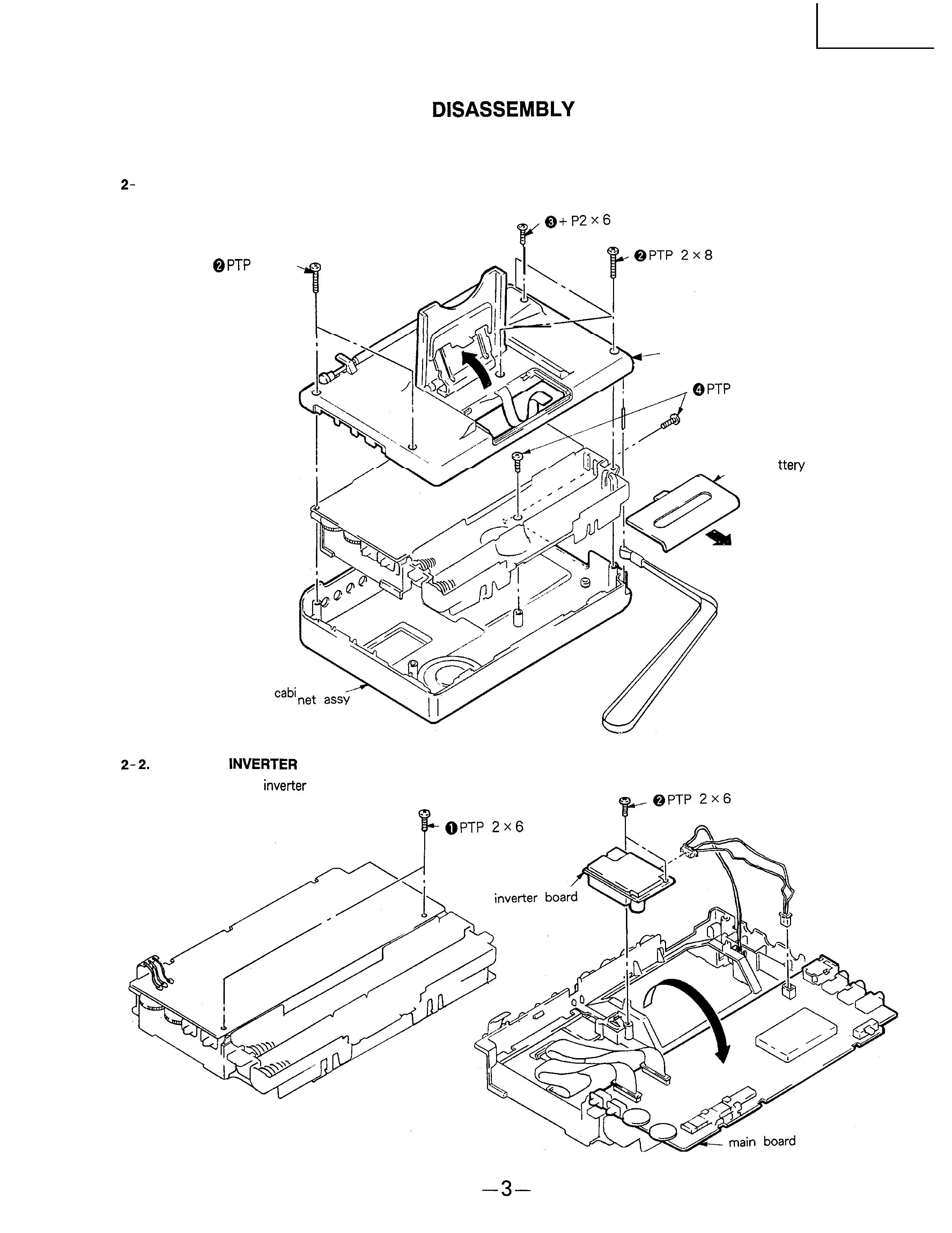
NOTE : Follow the disassembly procedure in the numerical order given.
1. FRONT AND REARCABINET ASSY
Revove the front and rear cabinet assy in the numerical order
given.
.
2x8
front
rear cabinet assy
2x6
@lid ba
case
MAIN AND
BOARD
Remove the main and
board in the numerical order
given.