FLOPPY DISK DRIVE
FDD MECHANICAL ADJUSTMENT MANUAL 2
Please use this manual with the service manual of the respective models.
Ver 1.0 2002. 12
FD-02H
-- 2 --
FDD MECHANICAL ADJUSTMENT MANUAL 2
SECTION 1
DISASSEMBLY
Note: Follow the disassembly procedure in the numerical order given.
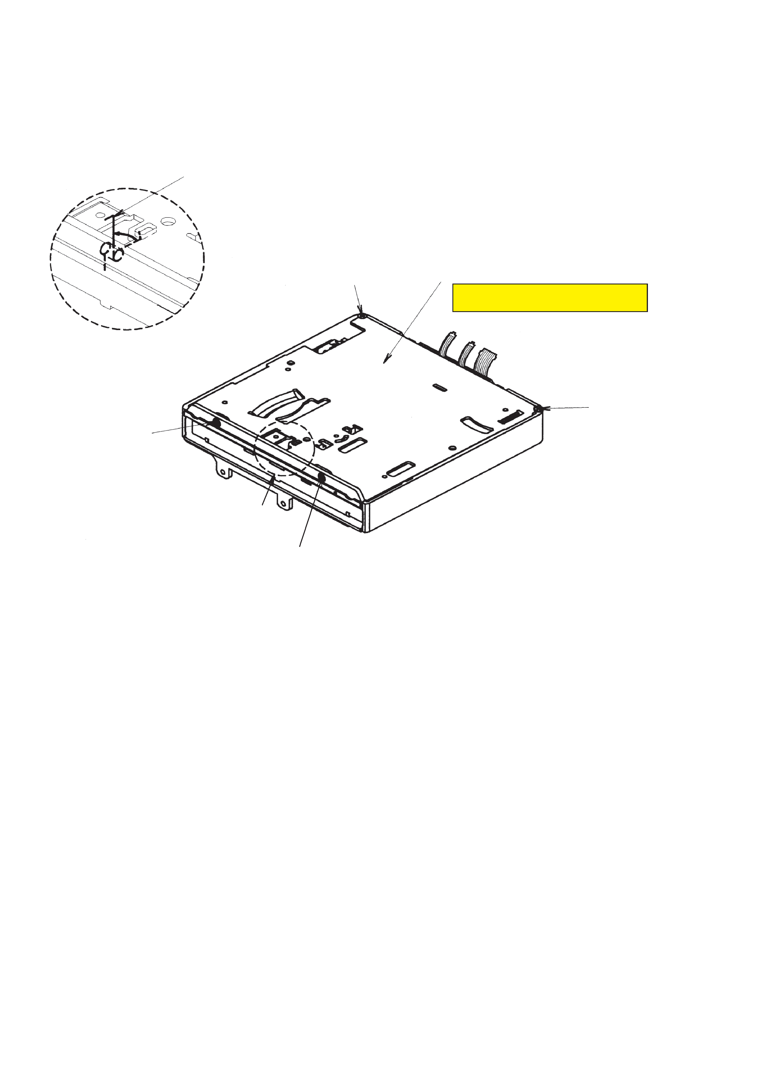
1-1. COVER ASSY 02 SST
1
Remove the TRSN SPR Flap 02 SST.
Detail A
Part A
3
Screw Cover
1.7 x 2.5 Black
3
Screw Cover 1.7 x 2.5 Black
4
Cover Assy 02 SST
2
Screw Cover 02 1.7 x 3.5
2
Screw Cover 02
1.7 x 3.5
Note: When remove the cover, be careful
not to injure a finger etc.
-- 3 --
FDD MECHANICAL ADJUSTMENT MANUAL 2
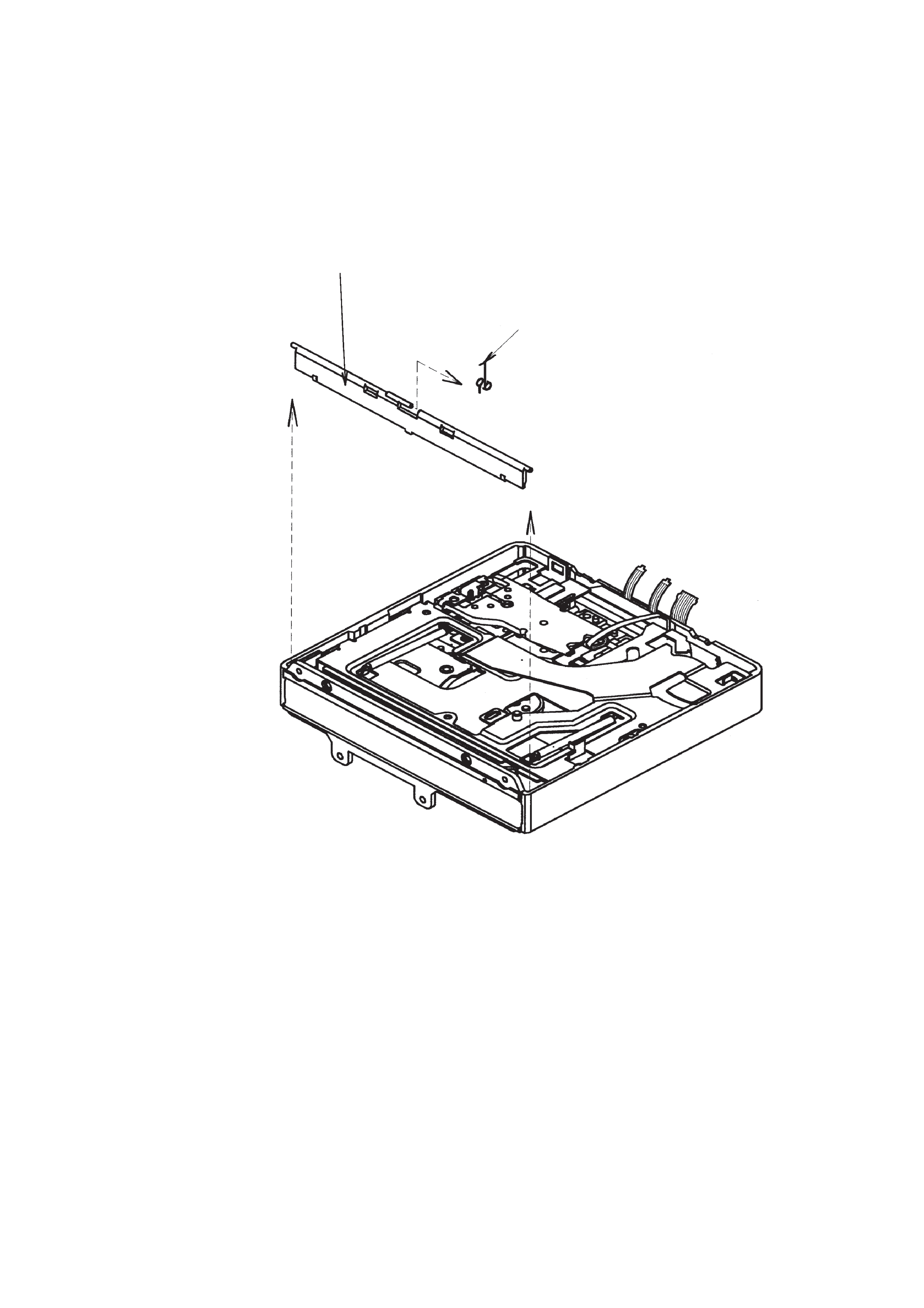
1-2. FLAP 02 SST
2
TRSN SPR Flap 02 SST
1
Flap 02 SST
Note 1: Be sure to hold the spring with your either hand, as it may fall into the drive when
installing the Flap 02 SST.
Note 2: When you lost the spring, remove the Base Assy 02 SST and checkinside the drive.
If you failed to find the spring, scrap the drive (including the Base Assy 02 SST).
-- 4 --
FDD MECHANICAL ADJUSTMENT MANUAL 2
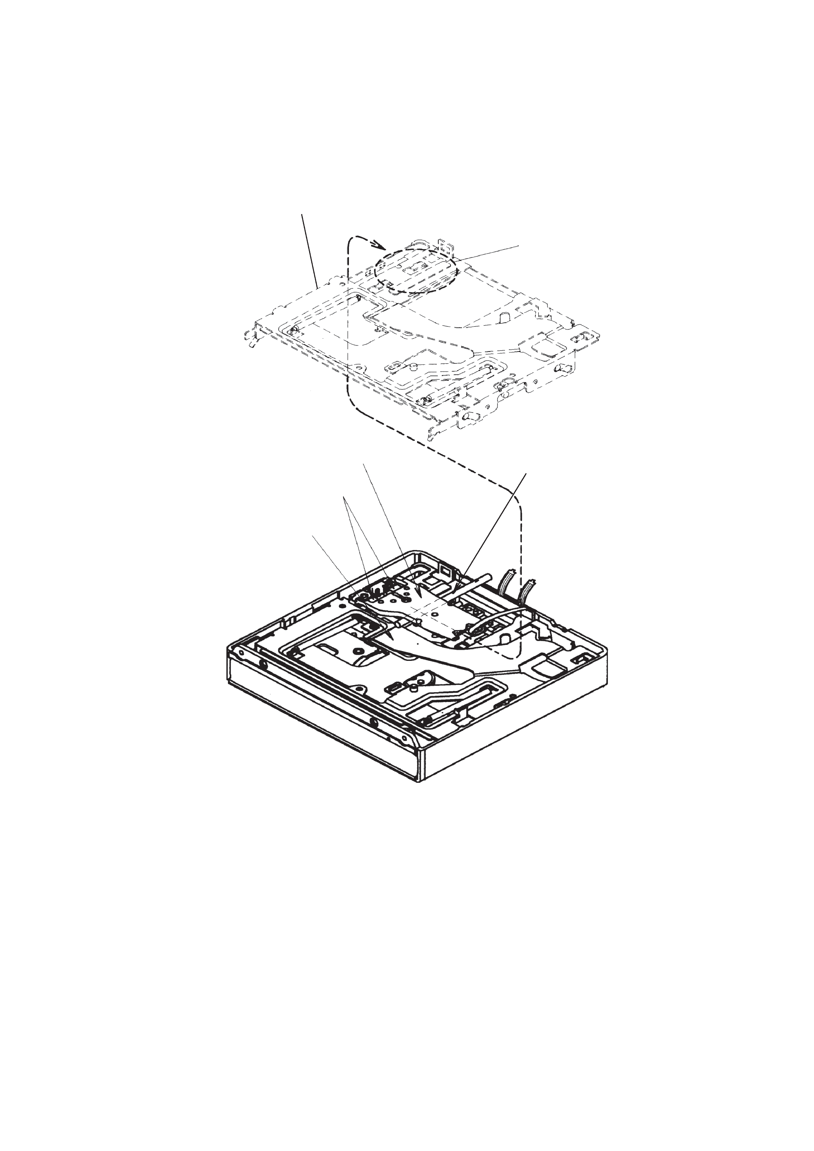
1-3. BASE ASSY 02 SST
Part C
Leaf Spring
HCA
Shaft
1
Inserting the shaft of special jig under
the bottom of HCA, set the drive.
2
Remove the Base Assy 02 SST, being careful so that the part C does not hit
the head piecs.
Note: Take care not to deform Leaf Spring by raising the HCA upper too much.
-- 5 --
FDD MECHANICAL ADJUSTMENT MANUAL 2
SECTION 2
ASSEMBLY
Note: Follow the assembly procedure in the numerical order given.
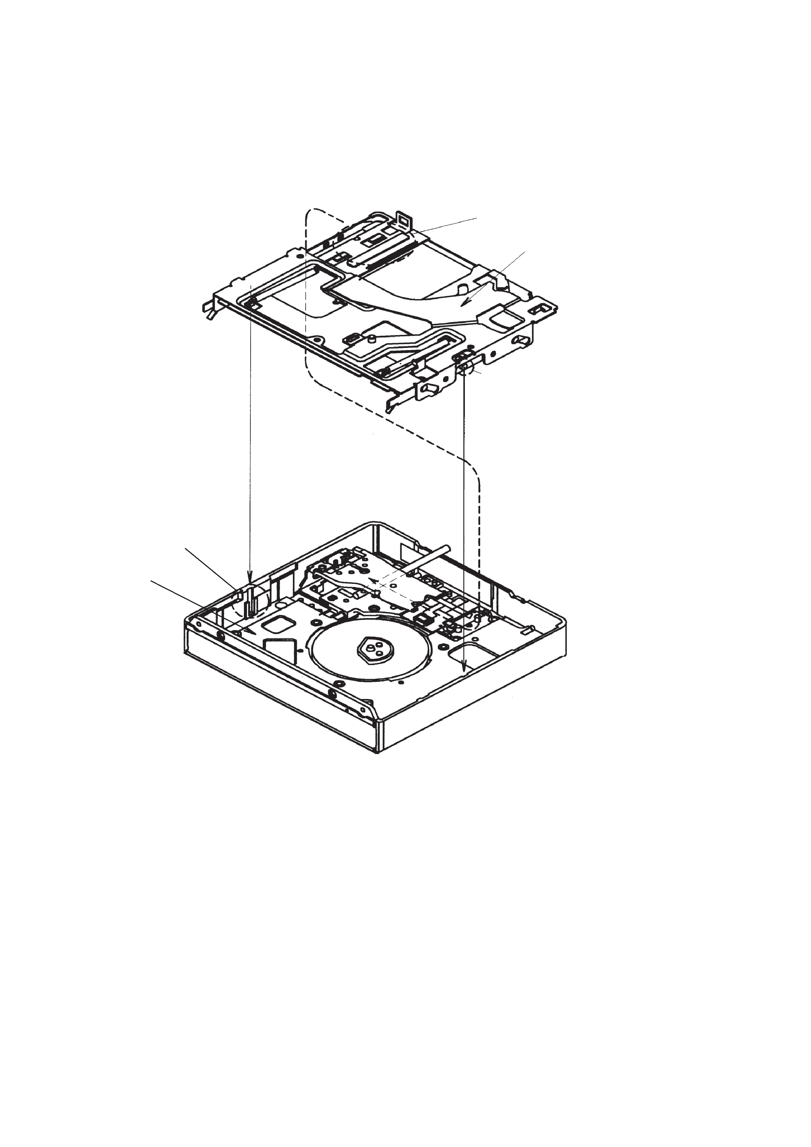
2-1. BASE ASSY 02 SST
Part C
Part A
(left and right 2 places)
Part B
(left and right 2 places)
Frame
1
Install the Base Assy 02 SST (9-885-028-95),
being careful so that the part C does not hit
the head piece.
(Engage convex portions (part A) on the sides
of Base Assy 02 SST with the slots (part B) in
the Frame.)