ECM-DS70P
SERVICE MANUAL
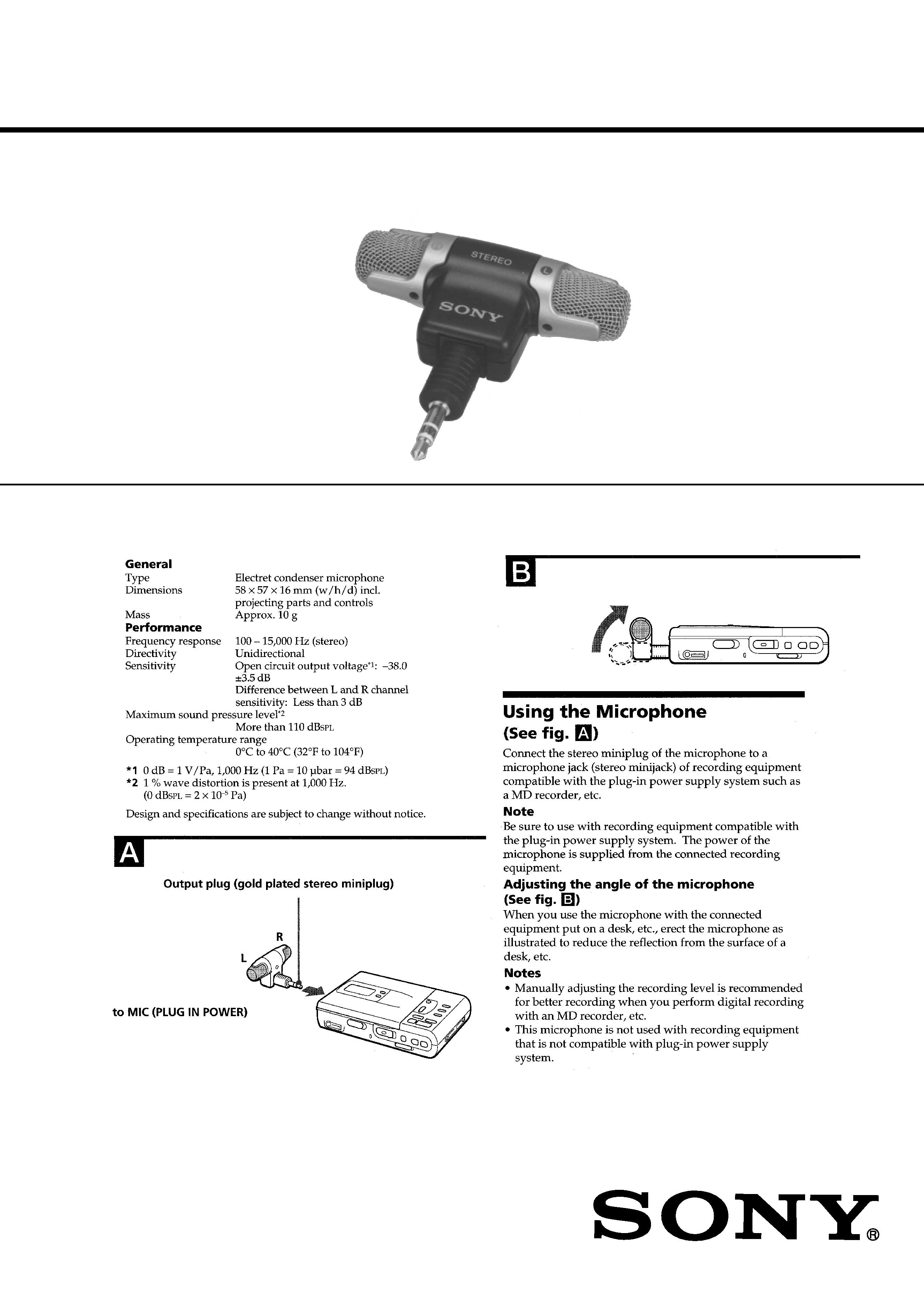
ELECTRET CONDENSER STEREO MICROPHONE
SPECIFICATIONS
US Model
Canadian Model
AEP Model
E Model
Ver 1.1 2001. 03
With SUPPLEMENT-1
(9-923-256-81)
9-923-256-12
2001C0200-1
© 2001.3
Sony Corporation
Audio Entertainment Group
General Engineering Dept.
2
SECTION 1
DIAGRAM
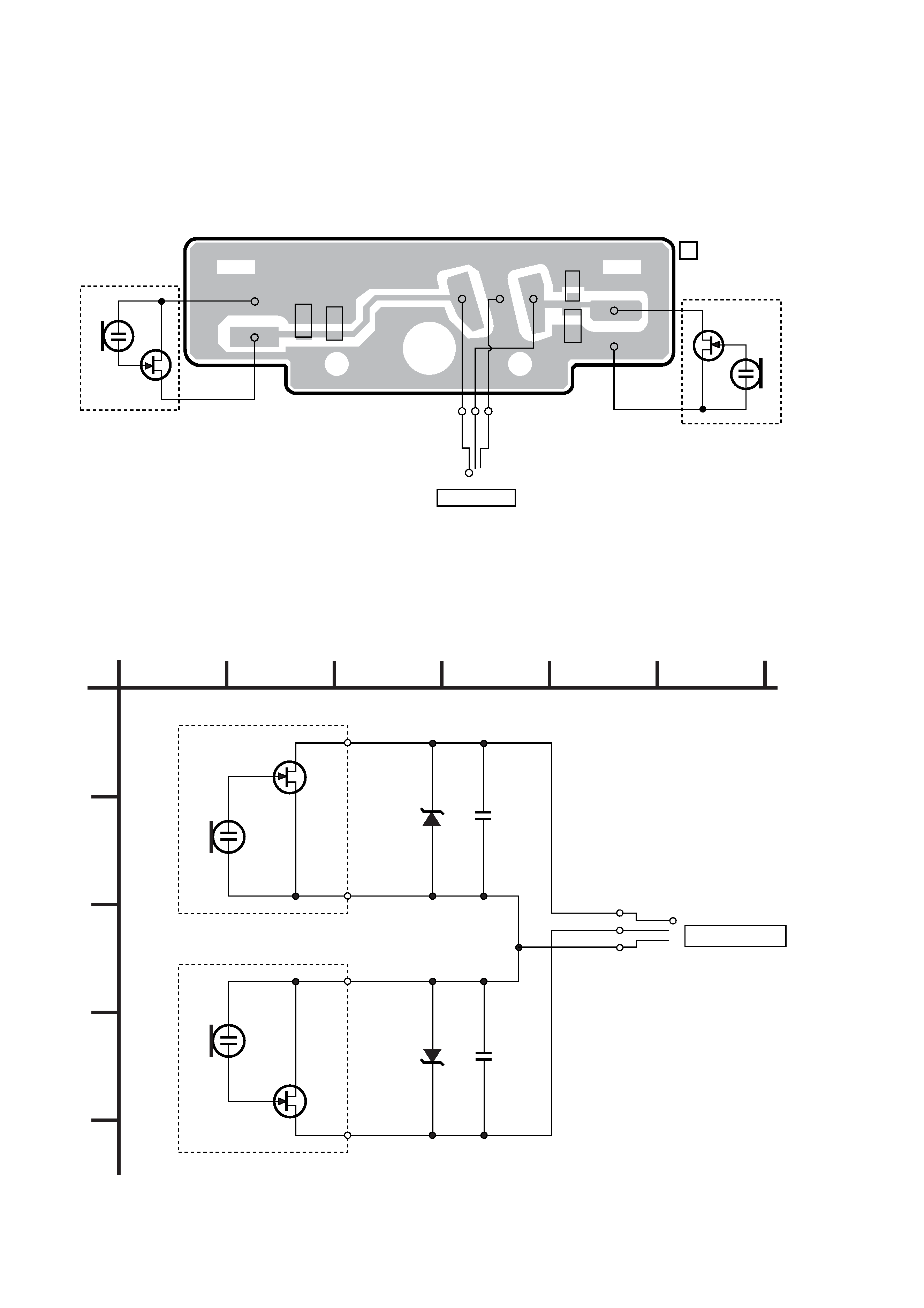
[PRINTED WIRING BOARD]
[SCHEMATIC DIAGRAM]
D1
C1
C2
GRN
GLD
RED
D2
P1
MIC OUTPUT
MIC 1
MIC 2
RED
RED
02
WHT
WHT
1-667-840-
11
[AMP BOARD]
C1
1000p
D1
UDZ-4.7
C2
1000p
D2
UDZ-4.7
S
02
S
MIC 2
MIC 1
P 1
MIC OUTPUT
L ch
R ch
1
A
B
C
D
23
4
5
6
ECM-DS70P
Note on Schematic Diagram:
Note:
· All capacitors are in
µF unless otherwise noted. pF: µµF
50 WV or less are not indicated except for electrolytics
and tantalums.
Note on Printed Wiring Boards:
Note:
· X : parts extracted from the component side.
· b : Pattern on the side which is seen.
3
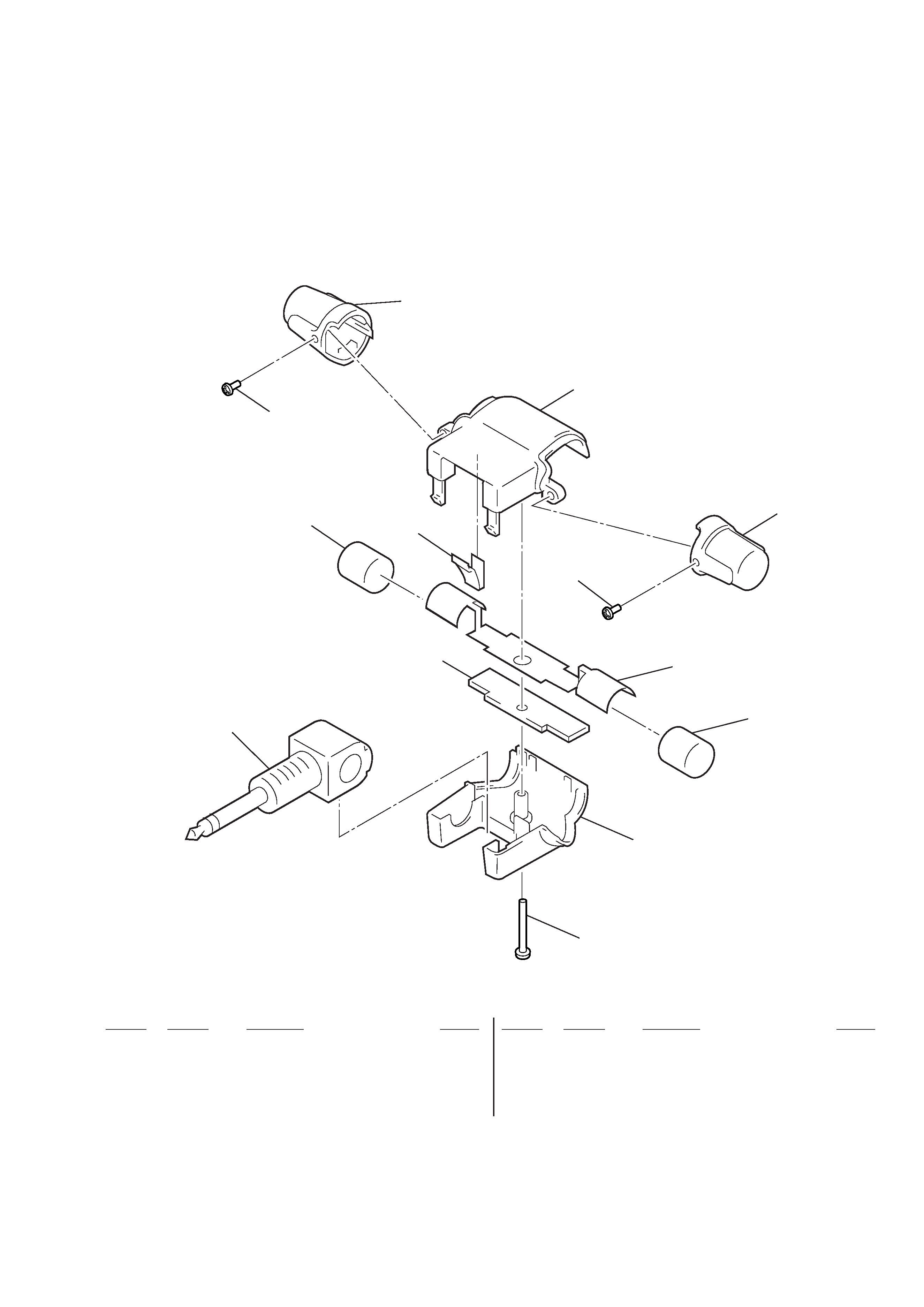
SECTION 2
EXPLODED VIEW
NOTE :
· -XX, -X mean standardized parts, so they
may have some difference from the original
one.
· Items marked " * "are not stocked since they
are seldom required for routine service. Some
delay should be anticipated when ordering
these items.
Ref. No.
Part No.
Description
Remark
Ref. No.
Part No.
Description
Remark
P1
1
2
2
3
4
5
6
7
(including 4)
9
8
4
not supplied
1
2-545-316-01 SPRING, CLICK
2
2-387-701-21 SCREW (1.4)
3
X-2542-154-1 GRILLE ASSY (R)
4
2-545-313-01 CASE, FRONT
5
X-2542-153-1 GRILLE ASSY (L)
* 6
1-667-840-11 AMP BOARD
7
A-4540-471-A CAPSULE ASSY
8
2-545-314-01 CASE, REAR
9
3-334-565-11 SCREW (B1.7 X 10), TAPPING
P1
1-782-912-11 CORD (WITH PLUG) (3 CORE) (MIC OUTPUT)
· The mechanical parts with no reference
number in the exploded views are not
supplied.

4
Ref. No.
Part No.
Description
Remark
NOTE :
· Due to standardization, replacements in the
parts list may be different from the parts
specified in the diagrams or the components
used on the set.
· Items marked " * "are not stocked since
they are seldom required for routine service.
Some delay should be anticipated when
ordering these items.
When indicating parts by reference num-
ber, please include the board.
SECTION 3
ELECTRICAL PARTS LIST
· CAPACITORS
uF :
µ F
*
1-667-840-11 AMP BOARD
**********
< CAPACITOR >
C1
1-163-009-11 CERAMIC CHIP
0.001uF
10%
50V
C2
1-163-009-11 CERAMIC CHIP
0.001uF
10%
50V
< DIODE >
D1
8-719-976-96 DIODE DTZ4.7C
D2
8-719-976-96 DIODE DTZ4.7C
************************************************************
MISCELLANEOUS
***************
P1
1-782-912-11 CORD (WITH PLUG) (3 CORE) (MIC OUTPUT)
************************************************************
ACCESSORIES & PACKING MATERIALS
********************************
3-860-993-11 MANUAL, INSTRUCTION
(ENGLISH,FRENCH,GERMAN,SPANISH,
DUTCH,SWEDISH,ITALIAN,PORTUGUESE)
ECM-DS70P
AMP
2001.03
ECM-DS70P
SUPPLEMENT - 1
File this Supplement with the Service Manual.
Subject : ADDITION OF ACCESORIES (US MODEL ONLY)
SERVICE MANUAL
US Model
Canadian Model
AEPModel
E Model
r
Added follwing Accesories (Service Manual See page 4)
1-757-949-11 CORD, MICROPHONE EXTENSION (US model only)
A-3052-666-A CLIP ASSY, HOLDER (US model only)
Ref. No.
Part No.
Description
Remark
9-923-256-81
2001C0200-1
© 2001.3
Sony Corporation
Audio Entertainment Group
General Engineering Dept.