SERVICE MANUAL
DVD/VIDEO CD/CD PLAYER
AEP Model
UK Model
E Model
Australian Model
SPECIFICATIONS
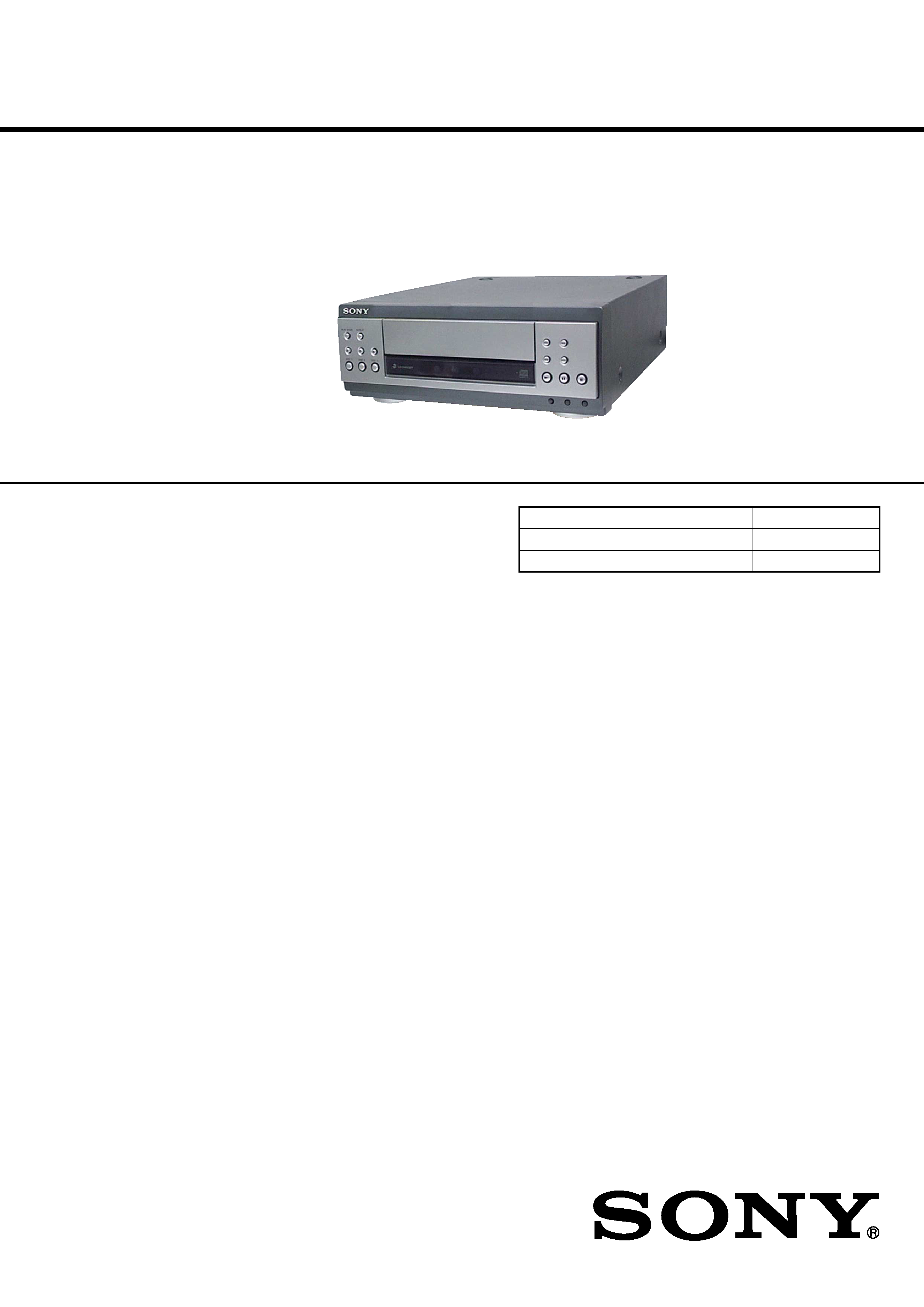
DVP-S9
Ver 1.0 2001.09
DVP-S9 is the DVD/Video CD/CD player
section in MHC-S9D.
Model Name Using Similar Mechanism
NEW
CD Mechanism Type
CDM63D
Optical Pick-up Name
KHM-240AAA
9-873-280-01
Sony Corporation
2001I0500-1
Home Audio Company
C
2001.9
Shinagawa Tec Service Manual Production Group
General
Power requirements
European model:
230 V AC, 50/60 Hz
Australian model:
230 240 V AC,
50/60 Hz
Mexican model:
120 V AC, 60 Hz
Korean model:
220 V AC, 60 Hz
Thailand model:
220 V AC, 50/60 Hz
Other models:
120 V, 220 V or
230 240 V AC,
50/60 Hz
Dimensions (w/h/d)
Approx. 280 x 108 x 330 mm
Mass
Approx. 2.9 kg
Design and specifications are subject to change
without notice.
DVD/Video CD/CD player section
Laser
Semiconductor laser
(
=660 nm/780 nm)
Emission duration:
continuous
Frequency response
DVD (PCM 48 kHz):
2 Hz 22 kHz = (
±1 dB)
CD: 2Hz 20 kHz =
(
±1 dB)
Signal-to-noise ratio
More than 90 dB
Dynamic range
More than 90 dB
Video color system format
NTSC, PAL
OPTICAL OUT
(Square optical connector jack, rear panel)
2
DVP-S9
SAFETY-RELATED COMPONENT WARNING!!
COMPONENTS IDENTIFIED BY MARK 0 OR DOTTED
LINE WITH MARK 0 ON THE SCHEMATIC DIAGRAMS
AND IN THE PARTS LIST ARE CRITICAL TO SAFE
OPERATION. REPLACE THESE COMPONENTS WITH
SONY PARTS WHOSE PART NUMBERS APPEAR AS
SHOWN IN THIS MANUAL OR IN SUPPLEMENTS PUB-
LISHED BY SONY.
The laser diode in the optical pick-up block may suffer electro-
static break-down because of the potential difference generated
by the charged electrostatic load, etc. on clothing and the human
body.
During repair, pay attention to electrostatic break-down and also
use the procedure in the printed matter which is included in the
repair parts.
The flexible board is easily damaged and should be handled with
care.
NOTES ON LASER DIODE EMISSION CHECK
The laser beam on this model is concentrated so as to be focused
on the disc reflective surface by the objective lens in the optical
pick-up block. Therefore, when checking the laser diode emis-
sion, observe from more than 30 cm away from the objective lens.
Notes on chip component replacement
· Never reuse a disconnected chip component.
· Notice that the minus side of a tantalum capacitor may be dam-
aged by heat.
Flexible Circuit Board Repairing
· Keep the temperature of the soldering iron around 270 °C dur-
ing repairing.
· Do not touch the soldering iron on the same conductor of the
circuit board. (within 3 times)
· Be careful not to apply force on the conductor when soldering
or unsoldering.
NOTES ON HANDLING THE OPTICAL PICK-UP
BLOCK OR BASE UNIT
CAUTION
Use of controls or adjustments or performance of procedures
other than those specified herein may result in hazardous ra-
diation exposure.
This appliance is
classified as a CLASS 1
LASER product. The
CLASS 1 LASER
PRODUCT MARKING
is located on the rear
exterior.
CAUTION
The use of optical instruments with this product will
increase eye hazard.
As the laser beam used in this CD/DVD Player is
harmful to eyes, do not attempt to disassemble the
cabinet. Refer servicing to qualified personnel only.
The following caution label is located inside the
apparatus.

3
DVP-S9
TABLE OF CONTENTS
1.
SERVICING NOTES ............................................... 4
2.
GENERAL ................................................................... 5
3.
DISASSEMBLY
3-1. Disassembly Flow ...........................................................
6
3-2. Cover ...............................................................................
7
3-3. CD Mechanism Deck (CDM63D) ..................................
7
3-4. MB Board ........................................................................
8
3-5. VIDEO Board ..................................................................
8
3-6. MAIN Board ...................................................................
9
3-7. Front Panel Section .........................................................
9
3-8. PANEL Board, SUB PANEL Board ............................... 10
3-9. Lid (CD) .......................................................................... 10
4.
TEST MODE .............................................................. 11
5.
ELECTRICAL ADJUSTMENTS ......................... 12
6.
DIAGRAMS
6-1. Block Diagram RF/SERVO Section ........................ 13
6-2. Block Diagram MAIN Section (1/2) ....................... 14
6-3. Block Diagram MAIN Section (2/2) ....................... 15
6-4. Block Diagram
INTERFACE CONTROL Section ............................ 16
6-5. Note For Printed Wiring Boards
and Schematic Diagrams ................................................ 17
6-6. Printed Wiring Board RF Board .............................. 18
6-7. Schematic Diagram RF Board ................................. 19
6-8. Printed Wiring Boards DISC SENSOR/DRIVER/
IN OUT SW/MOTOR/TRAY SENSOR Boards ......... 20
6-9. Schematic Diagram DISC SENSOR/DRIVER/
IN OUT SW/MOTOR/TRAY SENSOR Boards ......... 21
6-10. Printed Wiring Board
MB Board (Component Side) ................................... 22
6-11. Printed Wiring Board
MB Board (Conductor Side) ..................................... 23
6-12. Schematic Diagram MB Board (1/6) ....................... 24
6-13. Schematic Diagram MB Board (2/6) ....................... 25
6-14. Schematic Diagram MB Board (3/6) ....................... 26
6-15. Schematic Diagram MB Board (4/6) ....................... 27
6-16. Schematic Diagram MB Board (5/6) ....................... 28
6-17. Schematic Diagram MB Board (6/6) ....................... 29
6-18. Printed Wiring Board MAIN Board ........................ 30
6-19. Schematic Diagram MAIN Board ........................... 31
6-20. Printed Wiring Boards
PANEL/SUB PANEL/VIDEO Boards ..................... 32
6-21. Schematic Diagram
PANEL/SUB PANEL/VIDEO Boards ..................... 33
6-22. IC Pin Function Description ........................................... 37
7.
EXPLODED VIEWS
7-1. Case Section .................................................................... 47
7-2. Front Panel Section ......................................................... 48
7-3. Chassis Section ............................................................... 49
7-4. CD Mechanism Deck Section-1 (CDM63D) ................. 50
7-5. CD Mechanism Deck Section-2 (CDM63D) ................. 51
7-6. CD Mechanism Deck Section-3 (CDM63D) ................. 52
7-7. CD Mechanism Deck Section-4 (CDM63D) ................. 53
7-8. Optical Pick-up Section .................................................. 54
8.
ELECTRICAL PARTS LIST ............................... 55
4
DVP-S9
SECTION 1
SERVICING NOTES
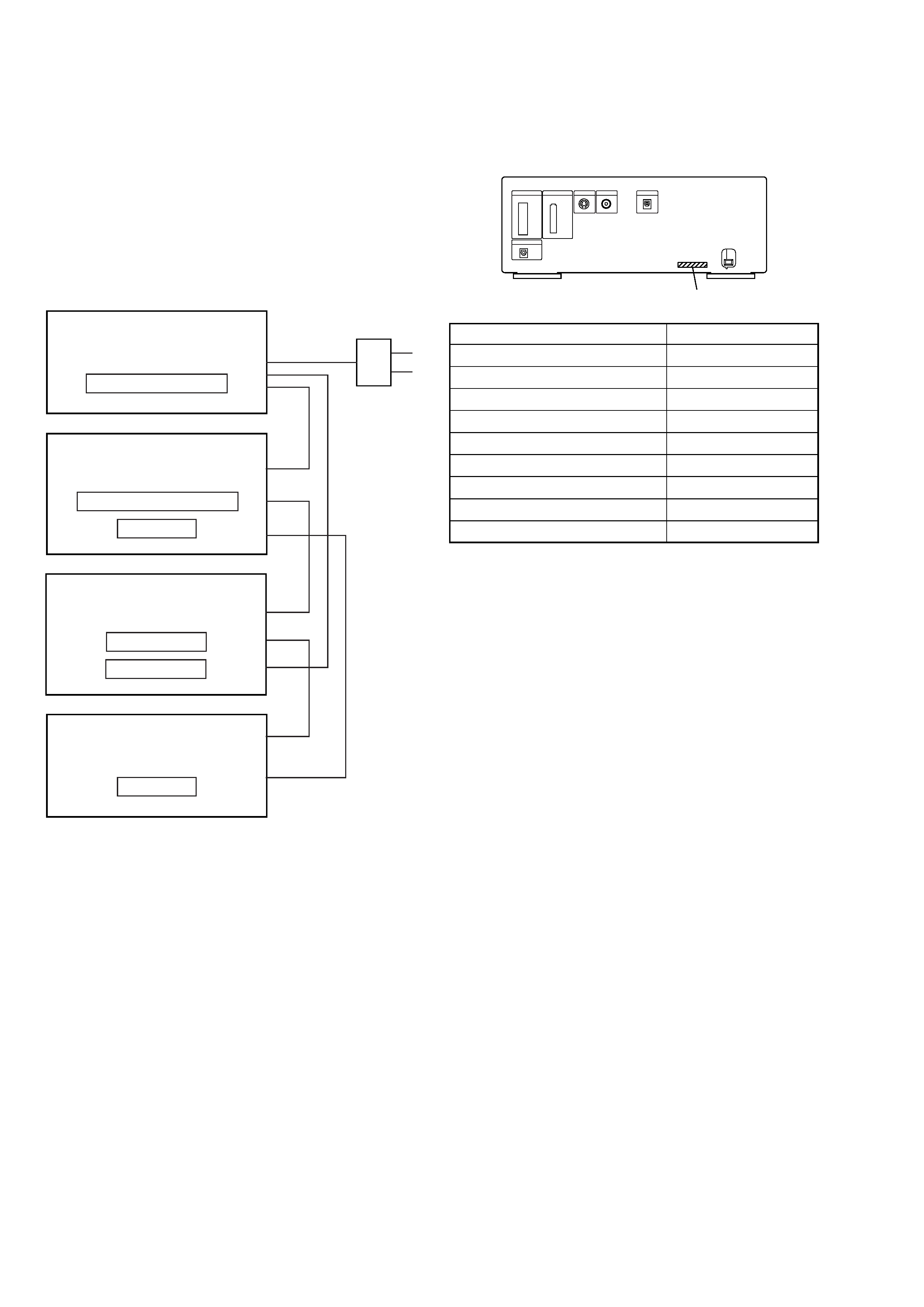
This set is a component of the MHC-S9D.
The MHC-S9D system configuration is as shown below, and there-
fore it does not operate normally unless all four components are
connected.
In performing the repair, connect all components with the system
cables.
Note: The precaution to the users is described on the label stuck on the
back panel (DVD/video CD/CD player) and in the troubleshooting
section in the Operation Manual.
System Configuration:
POWER SUPPLY
AC IN
TA
MASTER & GRAPHIC
µcon
ST
TC
µcon
TC
DISPLAY
HTC & MB
µcon
DVP
POWER BLOCK
MODEL IDENTIFICATION
- Back Panel -
Model
PART No.
AEP model
4-236-808-0[]
UK model
4-236-808-1[]
Korean model
4-236-808-3[]
Singapore model
4-236-808-4[]
Saudi Arabia model
4-236-808-5[]
Austrarian model
4-236-808-6[]
Thai model
4-236-808-7[]
E model
4-236-808-8[]
Mexican model
4-236-808-9[]
PART No.
5
DVP-S9
SECTION 2
GENERAL
This section is extracted from
instruction manual.
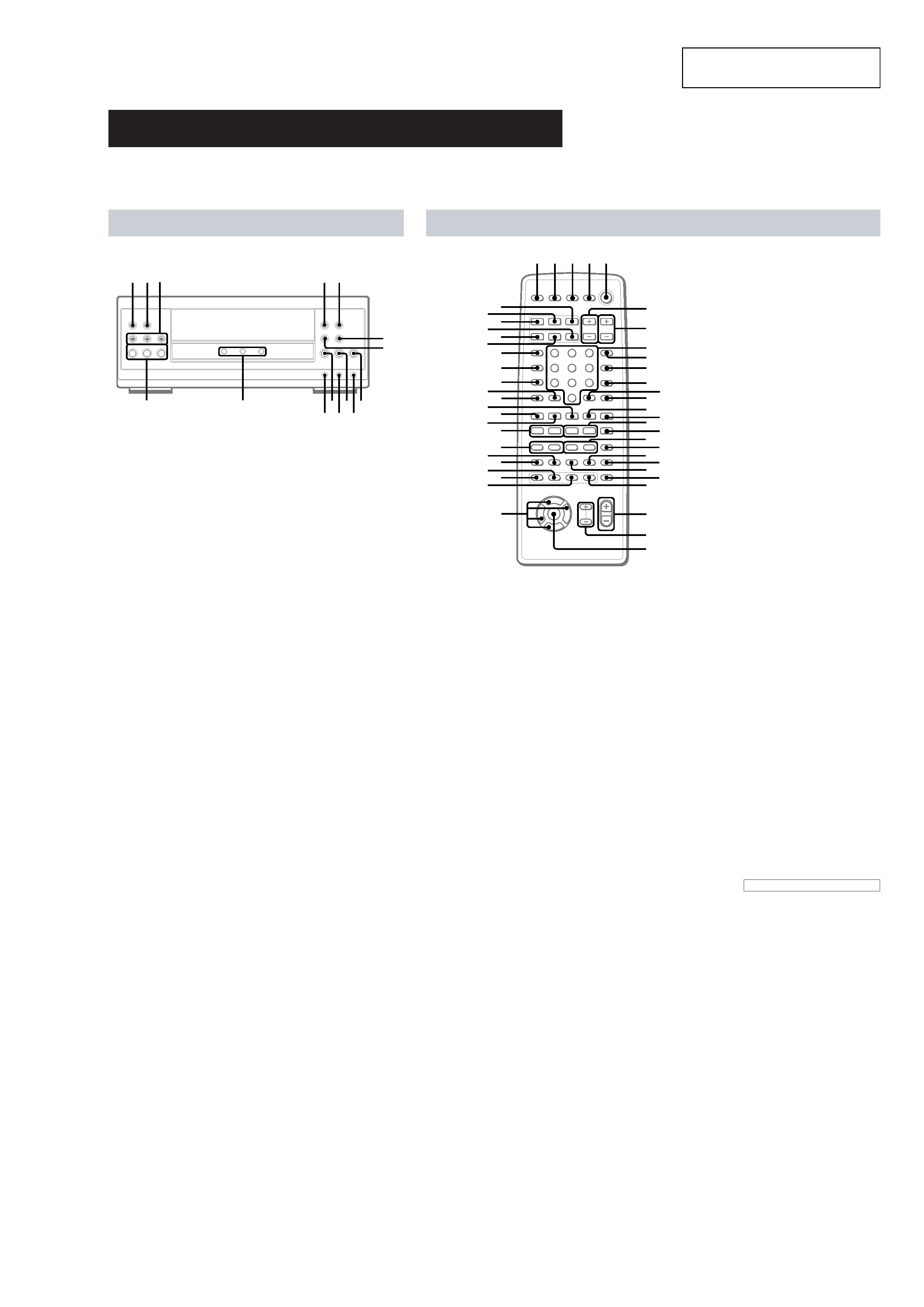
Parts Identification
Main unit
The items are arranged in alphabetical order.
Refer to the pages indicated in parentheses ( ) for details.
DISC 13 rd (25, 26)
DISC 13 indicators rs
DISC 13 Z (eject) ea (25, 26)
NEXT el (26, 27)
PLAY MODE wl (25, 28, 29, 46)
PREV ra (26, 27)
REPEAT e; (12, 30)
RETURN O ej (12, 27, 39, 40)
N SELECT (play) r; (2527,
41, 55, 60)
X (pause) ek (26)
x (stop) eh (12, 26, 27, 30, 38,
45, 55, 61)
. (go back) eg (26, 28, 30)
> (go forward) ef (26, 28, 30)
m (rewind) es (26)
M (fast forward) ed (26)
DVD/VIDEO CD/CD player
mM
.
HS
x
>
1
2
3
wl e;ea
es ed
ef
eg
ej
el
ra
eh
ek
r;
rs
rd
Remote control
ANGLE es (37)
AUDIO ws (34)
CLEAR qs (22, 29, 30, 36)
CLOCK/TIMER SELECT 3
(47, 56)
CLOCK/TIMER SET 2 (17, 47,
56)
DBFB ra (48)
D.SKIP 9 (26)
DIGITAL rf (57)
DISPLAY rj (17, 31, 32, 43, 54)
DVD DISPLAY wd (18, 19, 30,
3234, 3640)
DVD MENU wa (27)
DVD SET UP ql (18, 19, 24, 39)
ENTER wj
EQ ea (52)
EQ ON/OFF wl (53)
FILE SELECT +/ wh (48, 49,
53)
FUNCTION rd (18, 25, 27, 28,
36, 45, 46, 55, 57)
GROOVE rs (48)
KARAOKE PON (Except for
North American and European
models) el (54)
MD rh (57)
Numeric buttons 8 (28, 30)
PLAY MODE qa (25, 28, 29, 46)
REPEAT q; (30)
RETURN O qd (27, 39, 40)
SELECT DVD N eh (20, 25,
27, 29, 30)
SET UP wf (14, 16, 51, 53, 54)
SLEEP 1 (55)
SLOW t/T qk (26)
SPECTRUM ANALYZER rk
(54)
STEP c/C ef (26)
SUBTITLE ed (37)
SUR e; (51)
TAPE A nN ek (44)
TAPE B nN qf (44, 45)
TITLE w; (27)
TUNER/BAND ej (42)
TV @/1 4 (13)
TV CH +/ 7 (13)
TV/VIDEO rl (13)
TV VOL +/ 6 (13)
VIDEO rg (57)
VOL +/ wg
x
M
m
>
.
nN
O
X
T
t
C
c
V
v
Bb
12 3 4 5
e;
es
ef
ej
eg
6
7
9
8
q;
qa
qd
qs
qf
qg
qj
qh
qk
ql
wa
wd
ws
wf
w;
wg
wj
wh
wk
ed
wl
ea
eh
el
rs
ra
rd
ek
r;
rg
rj
rl
rf
rh
rk
BUTTON DESCRIPTIONS
@/1 (power) 5
X (pause) qj
x (stop) qg
m/M (rewind/fast forward),
TUNING /+ qh
./> (go back/go forward),
PRESET /+, PREV/NEXT eg
O
/o/P/p wk
>10 r;