MICROFILM
SERVICE MANUAL
US Model
Canadian Model
Chinese Model
Hong Kong Model
Singapore Model
CD/DVD PLAYER
DVP-S3000
RMT-D100E/D100U
SPECIFICATIONS
· Audio/video/S-link connecting cord (1) (US, Canadian)
· Audio/Video connecting cord (1)
(Chinese, Hong Kong, Singapore)
· S video cable (1)
· Remote commander (remote) RMT-D100U (1) (US, Canadian)
· Remote commander (remote) RMT-D100E
(Chinese, Hong Kong, Singapore)
· sony R6 (size AA) batteries (2)
Design and specifications are subject to change without notice.
2
SAFETY CHECK-OUT
LEAKAGE TEST
The AC leakage from any exposed metal part to earth ground
and from all exposed metal parts to any exposed metal part having
a return to chassis, must not exceed 0.5 mA (500 microamperes).
Leakage current can be measured by any one of three methods.
1.
A commercial leakage tester, such as the Simpson 229 or RCA
WT-540A. Follow the manufacturers' instructions to use these
instruments.
2.
A battery-operated AC milliammeter. The Data Precision 245
digital multimeter is suitable for this job.
3.
Measuring the voltage drop across a resistor by means of a
VOM or battery-operated AC voltmeter. The "limit" indica-
tion is 0.75V, so analog meters must have an accurate low-
voltage scale. The Simpson 250 and Sanwa SH-63Trd are ex-
amples of a passive VOM that is suitable. Nearly all battery
operated digital multimeters that have a 2V AC range are suit-
able. (See Fig. A)
1.
Check the area of your repair for unsoldered or poorly-sol-
dered connections. Check the entire board surface for solder
splashes and bridges.
2.
Check the interboard wiring to ensure that no wires are
"pinched" or contact high-wattage resistors.
3.
Look for unauthorized replacement parts, particularly transis-
tors, that were installed during a previous repair. Point them
out to the customer and recommend their replacement.
4.
Look for parts which, though functioning, show obvious signs
of deterioration. Point them out to the customer and recom-
mend their replacement.
5.
Check the line cord for cracks and abrasion. Recommend the
replacement of any such line cord to the customer.
6.
Check the B+ voltage to see it is at the values specified.
7.
Check the antenna terminals, metal trim, "metallized" knobs,
screws, and all other exposed metal parts for AC leakage. Check
leakage as described below.
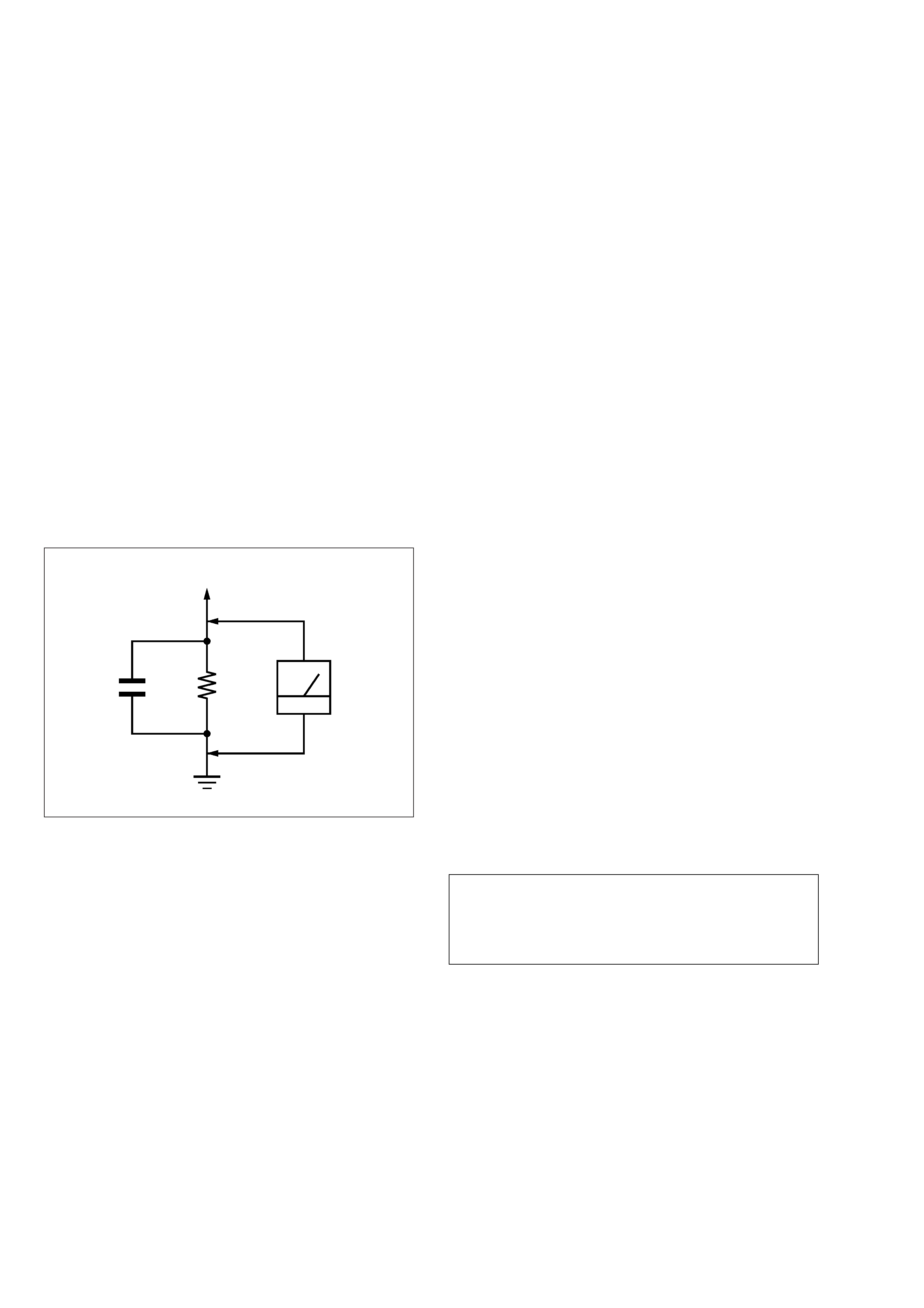
Fig. A
Using AC voltmeter to check AC leakage
After correcting the original service problem, perform the following
safety checks before releasing the set to the customer:
1.5 k
0.15
µF
AC
Voltmeter
(0.75 V)
To Exposed Metal
Parts on Set
Earth Ground
SAFETY-RELATED COMPONENT WARNING!!
COMPONENTS IDENTIFIED BY MARK
! OR DOTTED LINE
WITH MARK
! ON THE SCHEMATIC DIAGRAMS AND IN
THE PARTS LIST ARE CRITICAL TO SAFE OPERATION.
REPLACE THESE COMPONENTS WITH SONY PARTS WHOSE
PART NUMBERS APPEAR AS SHOWN IN THIS MANUAL OR
IN SUPPLEMENTS PUBLISHED BY SONY.
ATTENTION AU COMPOSANT AYANT RAPPORT
À LA SÉCURITÉ!
LES COMPOSANTS IDENTIFIÉS PAR UNE MARQUE
! SUR
LES DIAGRAMMES SCHÉMATIQUES ET LA LISTE DES
PIÈCES
SONT
CRITIQUES
POUR
LA
SÉCURITÉ
DE
FONCTIONNEMENT. NE REMPLACER CES COM- POSANTS
QUE PAR DES PIÈCES SONY DONT LES NUMÉROS SONT
DONNÉS DANS CE MANUEL OU DANS LES SUPPLÉMENTS
PUBLIÉS PAR SONY.
WARNING!!
WHEN SERVICING, DO NOT APPROACH THE LASER
EXIT WITH THE EYE TOO CLOSELY. IN CASE IT IS
NECESSARY TO CONFIRM LASER BEAM EMISSION,
BE SURE TO OBSERVE FROM A DISTANCE OF MORE
THAN 25 cm FROM THE SURFACE OF THE OBJEC-
TIVE LENS ON THE OPTICAL PICK-UP BLOCK.
CAUTION:
The use of optical instrument with this product will increase eye
hazard.
CAUTION
Use of controls or adjustments or performance procedures other
than those specified herein may result in hazardous radiation
exposure.

3
Section
Title
Page
TABLE OF CONTENTS
Service Note ............................................................................. 4
1.
GENERAL
This Player Can Play the Following Discs ....................... 1-1
Getting Started ............................................................... 1-1
Basic Operations ............................................................ 1-2
Playing Discs in Various Modes ...................................... 1-8
Setting and Adjustments ................................................. 1-10
Additional Information ..................................................... 1-12
2.
DISASSEMBLY
2-1.
Top Case Removal .......................................................... 2-1
2-2.
Front Panel Removal ...................................................... 2-1
2-3.
AU-201, 203 Board Removal .......................................... 2-1
2-4.
MB-80 Board Removal .................................................... 2-1
2-5.
MD Block Ass'y Removal ................................................ 2-2
2-6.
Try Removal .................................................................... 2-2
2-7.
Optical Pick-up Removal ................................................. 2-2
2-8.
TT-40 Board Removal ..................................................... 2-2
2-9.
Internal Views ................................................................. 2-3
2-10. Circuit Boards ................................................................. 2-4
3.
BLOCK DIAGRAMS
3-1.
Overall Block Diagram 1 (RF, Servo, Audio Power) ........ 3-1
3-2.
Overall Block Diagram 2 (Signal Process) ...................... 3-6
3-3.
RF/Servo Block Diagram ................................................ 3-11
3-4.
Data Process Block Diagram .......................................... 3-14
3-5.
Video Block Diagram ...................................................... 3-16
3-6.
System Control Block Diagram ....................................... 3-21
3-7.
Audio Block Diagram ...................................................... 3-24
3-8.
Mode Control Block Diagram .......................................... 3-27
3-9.
Power Supply Block Diagram .......................................... 3-30
4.
PRINTED WIRING BOARDS AND SCHEMATIC
DIAGRAMS
4-1.
Frame Schematic Diagram ............................................. 4-1
4-2.
Printed Wiring Boards and Schematic Diagrams ............ 4-5
TT-40, LM-56 Printed Wiring Boards ............................... 4-5
TT-40, LM-56 Schematic Diagram .................................. 4-7
MB-80 Printed Wiring Board ........................................... 4-12
MB-80 (Interface) Schematic Diagram ............................ 4-17
MB-80 (CPU) Schematic Diagram .................................. 4-21
MB-80 (Drive Control) Schematic Diagram ..................... 4-25
MB-80 (DVD Data Process) Schematic Diagram ............ 4-28
MB-80 (CD ROM Decode) Schematic Diagram .............. 4-31
MB-80 (MPEG Video Decode) Schematic Diagram ........ 4-35
MB-80 (Video EQ, Letter Box, Sub Picture)
Schematic Diagram ........................................................ 4-39
MB-80 (Audio Decode) Schematic Diagram ................... 4-42
MB-80 (Video) Schematic Diagram ................................ 4-45
MB-80 (Digital Servo) Schematic Diagram ..................... 4-51
MB-80 (RF Block) Schematic Diagram ........................... 4-55
MB-80 (Drive) Schematic Diagram ................................. 4-59
FP-611/619, PW-116/117 Printed Wiring Boards ............ 4-63
FP-611/619, PW-116/117 Schematic Diagram ................ 4-65
AU-201/203, PS-408/413 Schematic Diagram ............... 4-67
AU-201/203, PS-408/413 Printed Wiring Boards ............ 4-71
SR-740, SUB Printed Wiring Boards and
Schematic Diagram ......................................................... 4-74
SR-745, SUB Printed Wiring Boards and
Schematic Diagram ......................................................... 4-77
Section
Title
Page
5.
IC PIN FUNCTION DESCRIPTION
5-1.
Interface Control Pin Function (MB-75 Board IC021) ..... 5-1
5-2.
Drive Control Pin Function (MB-75 Board IC136) ........... 5-2
5-3.
Extended Output Port 0 (MB-75 Board IC147) ............... 5-3
5-4.
Extended Output Port 1 (MB-75 Board IC148) ............... 5-3
5-5.
Extended Output Port 2 (MB-75 Board IC149) ............... 5-3
5-6.
Extended Output Port 3 (MB-75 Board IC150) ............... 5-3
5-7
D/A Converter (MB-75 Board IC722) .............................. 5-3
5-8
System Control Pin Function (MB-75 Board IC090) ....... 5-4
6. TEST MODE
6-1.
Starting up Test Mode ..................................................... 6-1
6-2.
Syscon Diagnosis ........................................................... 6-1
6-3.
Drive Auto Adjustment .................................................... 6-10
6-4.
Drive Manual Operation .................................................. 6-13
6-4-1.
Drive Manual Operation wnu creen ........................... 6-13
6-4-2.
Disc Type ................................................................... 6-13
6-4-3.
Manual Control 1 ....................................................... 6-13
6-4-4.
Manual Control 2 ....................................................... 6-14
6-4-5.
Manual Control 3 ....................................................... 6-14
6-4-6.
Manual Adjust 1 ......................................................... 6-15
6-4-7.
Manual Adjust 2 ......................................................... 6-15
6-4-8.
Auto Adjust ................................................................ 6-15
6-4-9.
Check ......................................................................... 6-16
6-5.
Emergency History ......................................................... 6-18
6-6.
Other Checks .................................................................. 6-18
7.
ELECTRICAL ADJUSTMENT
7-1.
Power Supply Check ....................................................... 7-1
1.
PS-408/413 Board .......................................................... 7-1
2.
MB-80 Board ................................................................... 7-1
7-2.
+5.2 V Adjustment ........................................................... 7-1
7-3.
Adjustment of System Control ........................................ 7-2
1.
27 MHz Free Run ............................................................ 7-2
2.
22 MHz Adjustment ........................................................ 7-2
3.
33 MHz Check ................................................................ 7-2
4.
33 MHz Lock Check ........................................................ 7-2
5.
24 MHz Adjustment ........................................................ 7-3
6.
36 MHz Check ................................................................ 7-3
7.
36 MHz Lock Check ........................................................ 7-3
8.
16 MHz Check ................................................................ 7-3
7-4.
Adjustment of Video System
1.
Video Level Adjustment .................................................. 7-4
2.
S-Terminal Output Check ................................................ 7-4
3.
Checking Composite Video Output B-Y .......................... 7-4
4.
Checking Composite Video Output R-Y .......................... 7-5
5.
Checking Composite Video Output Y .............................. 7-5
6.
Checking S Video Output S-C ........................................ 7-5
7.
Checking S Video Output DC Level ................................ 7-5
7-5.
Adjustment Related Parts Arrangement ......................... 7-6
8.
REPAIR PARTS LIST
8-1.
Exploded Views .............................................................. 8-1
8-1-1.
Case Assembly .......................................................... 8-1
8-1-2.
Front Panel Assembly ................................................ 8-2
8-1-3.
Chassis Assembly ..................................................... 8-3
8-1-4.
DVD Mechanism Chassis Assembly (1) .................... 8-4
8-1-5.
DVD Mechanism Chassis Assembly (2) .................... 8-5
8-2.
Electrical Parts List ......................................................... 8-6
4
SERVICE NOTE
1.
DISK REMOVAL PROCEDURE
(at POWER OFF)
1)
Insert a cross-tip screwdriver into a hole at the bottom, and
rotate the cam gear 1 in direction A. (See Fig. 1)
Note: To prevent a damege of cam gear, rotate it in direction
A by 1/4 turn.
2)
Draw out the tray 2 in direction B by hand, and remove a
disk. (See Fig. 1)
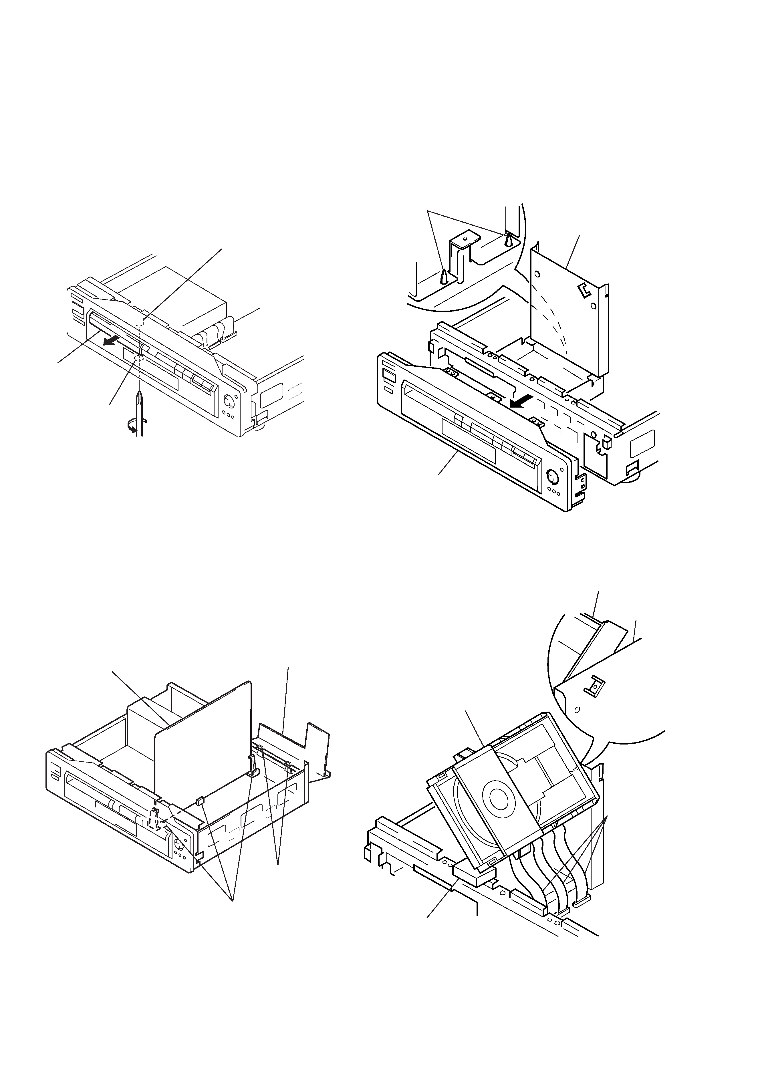
2.
HOW TO SERVICE AU-201, 203 AND MB-
80 BOARDS
1)
Remove the top case from the set. (Refer to 2-1)
2)
Remove the AU-201, 203 board. (Refer to 2-3)
Note: Do not disconnect wiring.
3)
Remove the MB-80 board. (Refer to 2-4)
Note: Do not disconnect wiring.
4)
Erect MB-80 board on three circuit board holders. (See. Fig. 2)
5)
Erect AU-201, 203 board on two claws. (See Fig. 2)
Fig. 1
Fig. 2
1 Cam gear
2 Tray
Hole
B
A
MB-80 board
AU-201 board
(US, Canadian model)
AU-203 board
(Chinese, Hong Kong, Singapore model)
Three circuit board
holders
Two claws
3.
HOW TO SERVICE THE MD BLOCK ASS'Y
1)
Remove the top case from the main unit. (Refer to 2-1)
2)
Remove the front panel. (Refer to 2-2)
Note: Do not disconnect wiring.
3)
Remove the MD block ass'y. (Refer to 2-5)
4)
Remove the MD upper cover, and mount as shown in Fig. 3.
Fig. 3
5)
Install the MD block ass'y as shown in Fig. 4.
Note: Place a cushion at the position A.
6)
Connect three flexible flat cables.
Fig. 4
Claws
MD upper cover
Front panel
MD block ass'y
MD upper
cover
MD block ass'y
Three flexible
flat cable
A
5
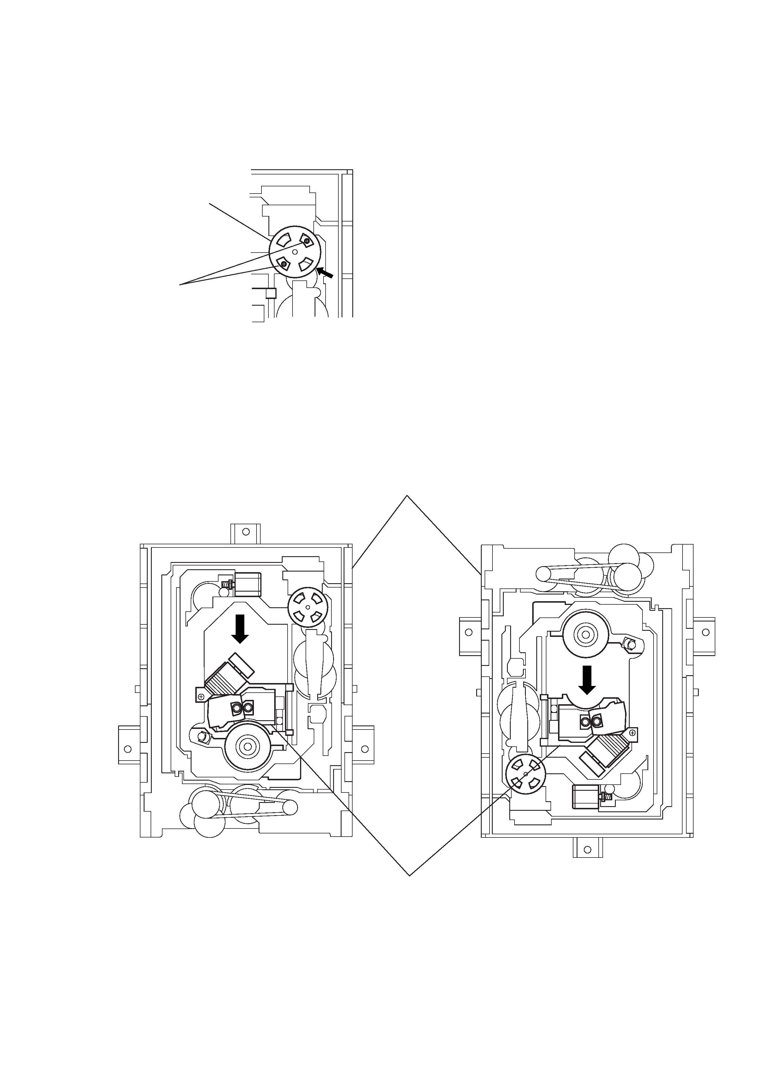
4.
NOTE ON MOUNTEING SLED MOTOR
1)
Push the sled motor assy 1 toward direction A. (See Fig.5)
2)
Tighten two screws 2 (M1.7
× 2.5).
3)
Raising the MD block assy 3 90 º with the side down.
confirm that the optical pick-up 4 falls by self weight.
(See Fig. 6)
4)
Further, with the front side of MD block assy 3 up, confirm
that the optical pick-up falls by self weight.
1 Sled motor ass'y
2 Two screws (M1.7
× 2.5)
Fig. 5
3 MD block ass'y
4 Optical pick-up
Front side
Lower
Upper
Upper
Front side
Lower
Fig. 6
A