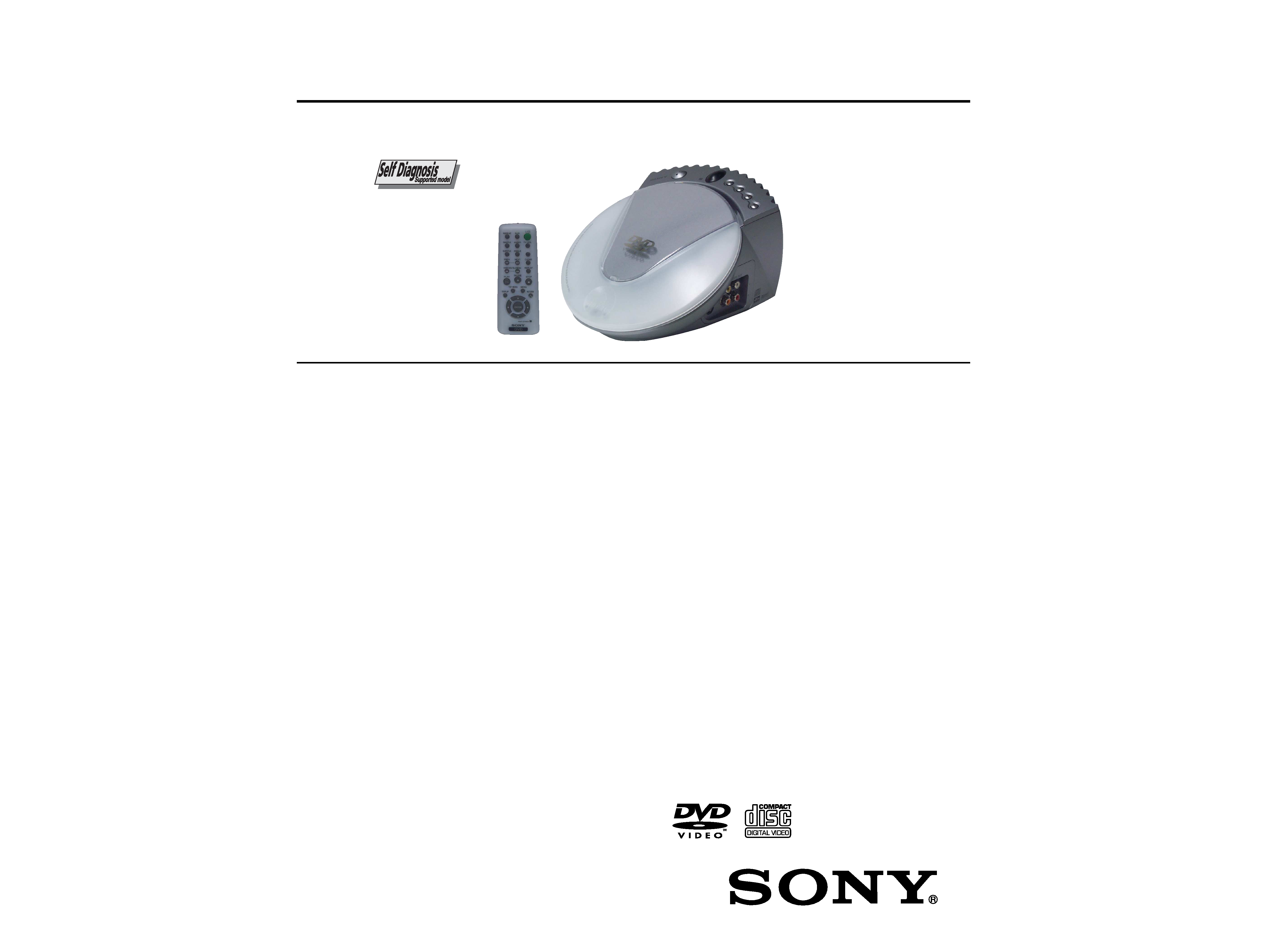
SERVICE MANUAL
US Model
Canadian Model
AEP Model
UK Model
E Model
CD/DVD PLAYER
DVP-PQ1
RMT-D148A
SPECIFICATIONS
System
Laser: Semiconductor laser
Signal format system:
U.S./Canadian models: NTSC
Eur opean models: PAL/NTSC
Asian models: NTSC/PAL (See the
"Display" section in "Troubleshooting"
to switch systems.)
Outputs
(Jack name: Jack type/Output level/
Load impedance)
AUDIO OUT L/R: Phonojack/2Vrms/10k
DIGITAL OUT (COAXIAL):Phonojack/0.5Vpp/75
VIDEO OUT: Phonojack/1.0Vpp/75
S-VIDEO OUT:4-pin mini DIN/
Y: 1.0Vpp,
C: 0.3Vpp (PAL), 0.286Vpp (NTSC)/
75
General
Power requirements:
U.S./Canadian models: 120V, 60Hz
Eur opean/Asian models: 220-240V ,
50/60Hz
Power consumption: 9W
Dimensions (approx.): 190
×135 × 235mm (7× 5 × 9in.)
(w/h/d)
Mass (approx.): 1.3kg (2.9lbs)
Operating temperature: 5
°C to 35 °C (41F to 95F)
Operating humidity: 25-80%
Supplied accessories
Operating Instructions (1)
Audio/video cord (1)
Remote (1)
AA (R6) size batteries (2)
EURO AV adaptor (For European models only) (1)
Design sheet
Specifications and design are subject to change
without notice.
ENERGY STAR® is a U.S. registered mark. As an
ENERGY STAR® Partner, Sony Corporation has
determined that this product meets the ENERGY STAR®
guidelines for energy efficiency.
2
WARNING!!
WHEN SERVICING, DO NOT APPROACH THE LASER
EXIT WITH THE EYE TOO CLOSELY. IN CASE IT IS
NECESSARY TO CONFIRM LASER BEAM EMISSION,
BE SURE TO OBSERVE FROM A DISTANCE OF
MORE THAN 25 cm FROM THE SURFACE OF THE
OBJECTIVE LENS ON THE OPTICAL PICK-UP BLOCK.
CAUTION
Use of controls or adjustments or performance of procedures
other than those specified herein may result in hazardous ra-
diation exposure.
ATTENTION AU COMPOSANT AYANT RAPPORT
À LA SÉCURITÉ!
LES COMPOSANTS IDENTIFIÉS PAR UNE MARQUE 0
SUR LES DIAGRAMMES SCHÉMATIQUES ET LA LISTE
DES PIÈCES SONT CRITIQUES POUR LA SÉCURITÉ
DE FONCTIONNEMENT. NE REMPLACER CES COM-
POSANTS QUE PAR DES PIÈCES SONY DONT LES
NUMÉROS SONT DONNÉS DANS CE MANUEL OU
DANS LES SUPPLÉMENTS PUBLIÉS PAR SONY.
SAFETY-RELATED COMPONENT WARNING!!
COMPONENTS IDENTIFIED BY MARK 0 OR DOTTED
LINE WITH MARK 0 ON THE SCHEMATIC DIAGRAMS
AND IN THE PARTS LIST ARE CRITICAL TO SAFE
OPERATION. REPLACE THESE COMPONENTS WITH
SONY PARTS WHOSE PART NUMBERS APPEAR AS
SHOWN IN THIS MANUAL OR IN SUPPLEMENTS PUB-
LISHED BY SONY.
CAUTION:
The use of optical instrument with this product will increase eye
hazard.
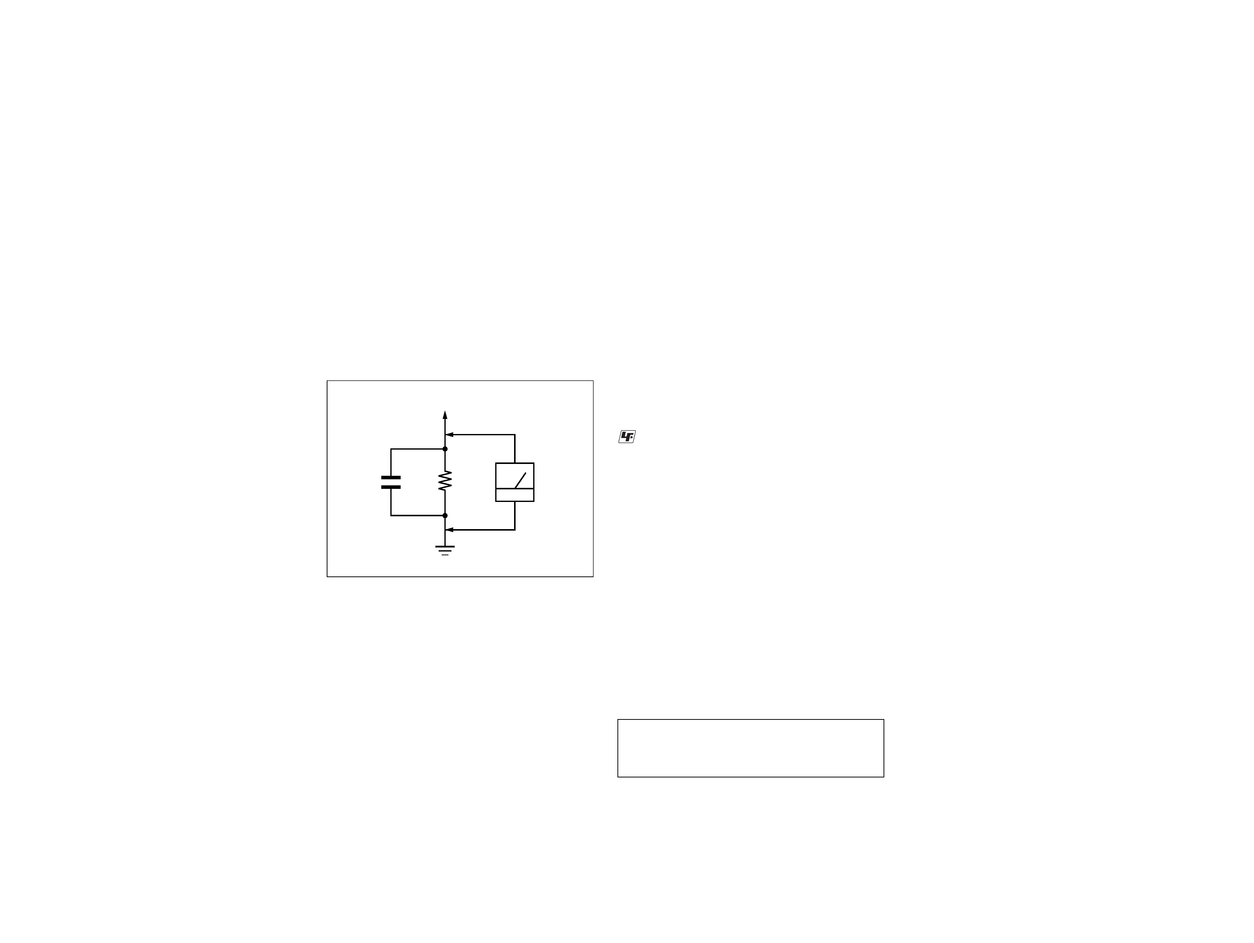
Fig. A.
Using an AC voltmeter to check AC leakage.
1.5 k
0.15 µF
AC
voltmeter
(0.75 V)
To Exposed Metal
Parts on Set
Earth Ground
LEAKAGE TEST
The AC leakage from any exposed metal part to earth ground
and from all exposed metal parts to any exposed metal part having
a return to chassis, must not exceed 0.5 mA (500 microamperes).
Leakage current can be measured by any one of three methods.
1. A commercial leakage tester, such as the Simpson 229 or RCA
WT-540A. Follow the manufacturers' instructions to use these
instruments.
2. A battery-operated AC milliammeter. The Data Precision 245
digital multimeter is suitable for this job.
3. Measuring the voltage drop across a resistor by means of a
VOM or battery-operated AC voltmeter. The "limit" indica-
tion is 0.75V, so analog meters must have an accurate low-
voltage scale. The Simpson 250 and Sanwa SH-63Trd are ex-
amples of a passive VOM that is suitable. Nearly all battery
operated digital multimeters that have a 2V AC range are suit-
able. (See Fig. A)
1. Check the area of your repair for unsoldered or poorly-sol-
dered connections. Check the entire board surface for solder
splashes and bridges.
2. Check the interboard wiring to ensure that no wires are
"pinched" or contact high-wattage resistors.
3. Look for unauthorized replacement parts, particularly transis-
tors, that were installed during a previous repair. Point them
out to the customer and recommend their replacement.
4. Look for parts which, though functioning, show obvious signs
of deterioration. Point them out to the customer and recom-
mend their replacement.
5. Check the line cord for cracks and abrasion. Recommend the
replacement of any such line cord to the customer.
6. Check the B+ voltage to see it is at the values specified.
7. Check the antenna terminals, metal trim, "metallized" knobs,
screws, and all other exposed metal parts for AC leakage.
Check leakage as described below.
SAFETY CHECK-OUT
After correcting the original service problem, perform the following
safety checks before releasing the set to the customer:
: LEAD FREE MARK
Unleaded solder has the following characteristics.
· Unleaded solder melts at a temperature about 40 °C higher than
ordinary solder.
Ordinary soldering irons can be used but the iron tip has to be
applied to the solder joint for a slightly longer time.
Soldering irons using a temperature regulator should be set to
about 350 °C .
Caution: The printed pattern (copper foil) may peel away if the
heated tip is applied for too long, so be careful!
· Strong viscosity
Unleaded solder is more viscous (sticky, less prone to flow) than
ordinary solder so use caution not to let solder bridges occur
such as on IC pins, etc.
· Usable with ordinary solder
It is best to use only unleaded solder but unleaded solder may
also be added to ordinary solder.

3
TABLE OF CONTENTS
Section
Title
Page
Section
Title
Page
Service Note ............................................................................ 4
1.
GENERAL ................................................................... 1-1
2.
DISASSEMBLY
2-1.
LID Assembly Removal ................................................. 2-1
2-2.
Disk Base Assembly Removal ...................................... 2-1
2-3.
Base Unit Removal ........................................................ 2-1
2-4.
BU Holder Removal ....................................................... 2-1
2-5.
SW-370 Board Removal ................................................ 2-2
2-6.
Jack Plate Removal ....................................................... 2-2
2-7.
Lower Case Removal .................................................... 2-2
2-8.
Power Switching Regulator Block Removal .................. 2-2
2-9.
Shield Plate Removal .................................................... 2-3
2-10. AV-65 Board Removal ................................................... 2-3
2-11. IF-95 Board Removal .................................................... 2-3
2-12. MB-103 Board Removal ................................................ 2-3
2-13. Circuit Boards Location ................................................. 2-4
3.
BLOCK DIAGRAMS
3-1.
Overall Block Diagram ................................................... 3-1
3-2.
RF/Servo Block Diagram ............................................... 3-3
3-3.
Signal Processor Block Diagram .................................. 3-5
3-4.
System Control Block Diagram ..................................... 3-7
3-5.
Video/Audio Block Diagram .......................................... 3-9
3-6.
Interface Control Block Diagram ................................... 3-11
3-7.
Power 1 Block Diagram ................................................. 3-13
3-8.
Power 2 Block Diagram ................................................. 3-15
4.
PRINTED WIRING BOARDS AND SCHEMATIC
DIAGRAMS
4-1.
Frame Schematic Diagram ............................................ 4-3
4-2.
Printed Wiring Boards and Schematic Diagrams ......... 4-5
MB-103 Printed Wiring Board ....................................... 4-5
MB-103 (RF AMP, SERVO) Schematic Diagram .......... 4-9
MB-103 (ARP, SERVO DSP) Schematic Diagram ........ 4-11
MB-103 (AV DECODER) Schematic Diagram .............. 4-13
MB-103 (DRIVE) Schematic Diagram .......................... 4-15
MB-103 (SYSTEM CONTROL)
Schematic Diagram ....................................................... 4-17
MB-103 (CLOCK GENERATOR AUDIO D/A
CONVERTER) Schematic Diagram .............................. 4-19
AV-65 Printed Wiring Board .......................................... 4-21
AV-65 (AUDIO/VIDEO OUT) Schematic Diagram ........ 4-23
IF-95 Printed Wiring Board ........................................... 4-25
IF-95 (IF CON) Schematic Diagram ............................. 4-27
SW-370 (FUNCTION SWITCH) Printed Wiring Board
and Schematic Diagram ................................................ 4-29
SW-371 (DOOR SWITCH) Printed Wiring Board
and Schematic Diagram ................................................ 4-31
DPSN-20CP (SWITCHING REGULATOR)
Printed Wiring Board US, CND ................................. 4-32
DPSN-20CP (SWITCHING REGULATOR)
Schematic Diagram US, CND ................................... 4-33
DPSN-20CP-2 (SWITCHING REGULATOR)
Schematic Diagram AEP, UK, E ............................... 4-35
DPSN-20CP-2 (SWITCHING REGULATOR)
Printed Wiring Board AEP, UK, E .............................. 4-37
5.
IC PIN FUNCTION DESCRIPTION
5-1.
System Control Pin Function
(MB-103 Board IC104) .................................................. 5-1
6.
TEST MODE
6-1.
General Description ...................................................... 6-1
6-2.
Starting Test Mode ........................................................ 6-1
6-3.
Syscon Diagnosis .......................................................... 6-1
6-4.
Drive Auto Adjustment .................................................. 6-5
6-5.
Drive Manual Operation ................................................ 6-7
6-6.
Emergency History ........................................................ 6-10
6-7.
Version Information ....................................................... 6-11
6-8.
Video Level Adjustment ................................................ 6-11
6-9.
Troubleshooting ............................................................. 6-11
7.
ELECTRICAL ADJUSTMENT
7-1.
Power Supply Check ..................................................... 7-1
7-2.
Adjustment of Video System ......................................... 7-2
1.
Video Level Adjustment ................................................ 7-2
2.
Checking S Video Output S-Y ....................................... 7-2
3.
Checking S Video Output S-C ....................................... 7-2
7-3. Adjustment Related Parts Arrangement ....................... 7-4
8.
REPAIR PARTS LIST
8-1.
Exploded Views ............................................................. 8-1
8-1-1. Disk Base Section .................................................... 8-1
8-1-2. Lower Case Section ................................................. 8-2
8-2.
Electrical Parts List ....................................................... 8-3
4
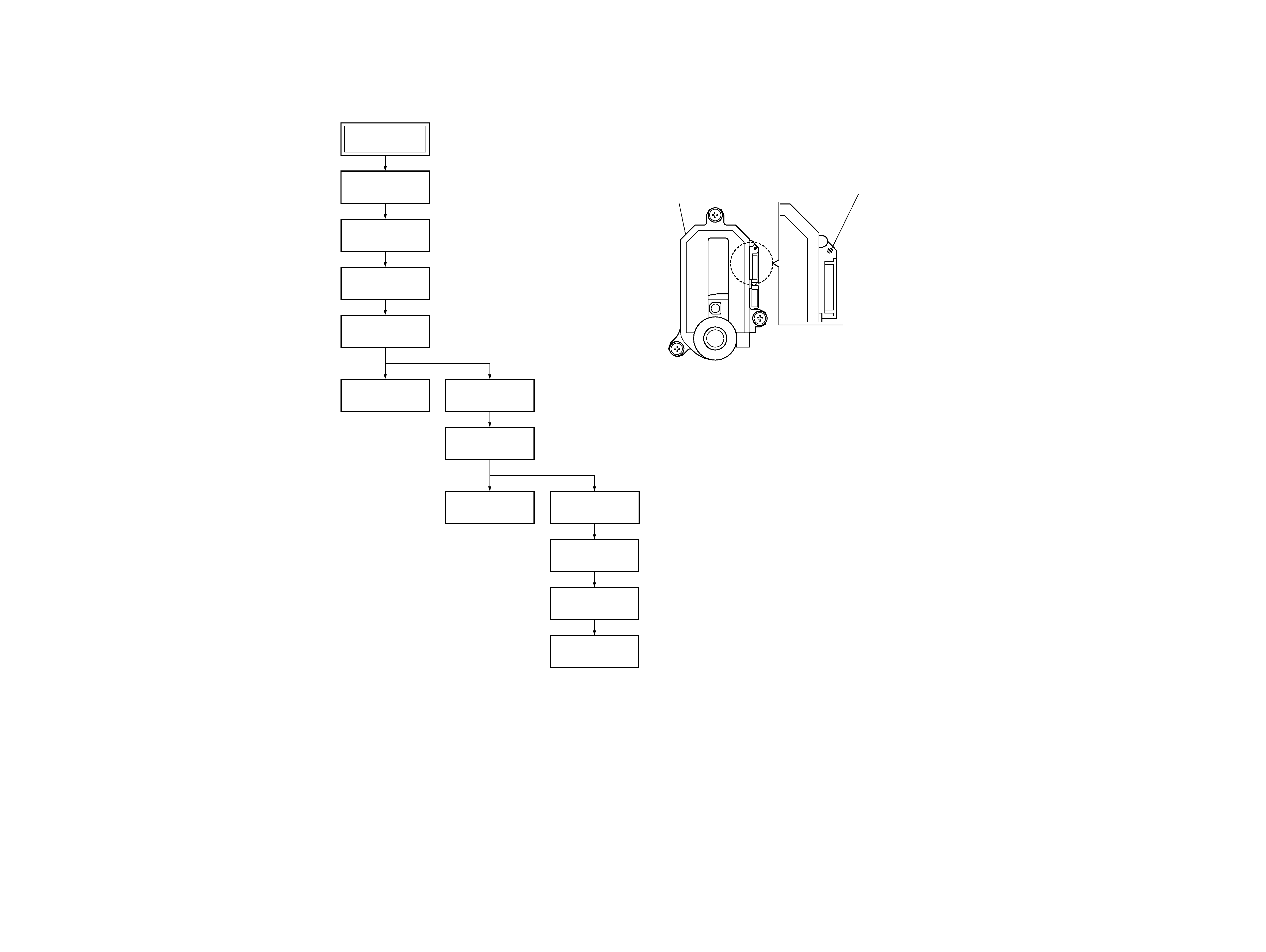
SERVICE NOTE
1.
DISASSEMBLY
·This set can be disassembled in the order shown below.
Set
Lid Assembly
(Page 2-1)
BU Holder
(Page 2-1)
SW-370 Board
(Page 2-2)
Disk Base Assembly
(Page 2-1)
Base Unit
(Page 2-1)
Jack Plate
(Page 2-2)
Lower Case
(Page 2-2)
AV-65 Board
(Page 2-3)
IF-95 Board
(Page 2-3)
MB-103 Board
(Page 2-3)
Shield Plate
(Page 2-3)
Power Switching
Regulator Block
(Page 2-2)
2.
PRECAUTIONS FOR USE OF BASE UNIT
As the laser diode in the base unit is easily damaged by static
electricity, desolder the laser tap of the flexible board of the base
unit when using it.
Before disconnecting the connector, solder first. Before connect-
ing the connector, be careful not to remove the solder. Also take
adequate measures to prevent damage by static electricity. Handle
the flexible board with care as it breaks easily.
Base unit
Laser tap
DVP-PQ1
1-1
1-2
SECTION 1
GENERAL
This section is extracted from instruction
manual (3-075-713-11).
Playable discs
and special
words
If you experience any of the following
difficulties while using the player , use this
troubleshooting guide to help remedy the
problem. Should any problem persist, consult
your near est Sony dealer .
Power
The player does not turn on.
1 Connect the power cord (mains lead)
securely .
1 Close the lid of the player until it clicks.
Display
There is no picture.
The picture is distorted.
1 Check to see if the player is connected
securely .
1 Check to see if the connecting cord is
damaged.
1 Check the connection and change the video
input on the TV so that the pictur
e output
from this player is displayed on the TV
scr een.
1 If the video signal from your DVD player is
output to your TV via a VCR, the copy-
protection signal of some DVD pr
ograms
could affect the pictur e quality. If you still
experience problems after connecting this
player directly to your TV, try connecting to
the S VIDEO input of your TV, if it has one.
1 For Asian models only:
If the player 's menu display or the Setup
Display is distorted, change the color
system of the player to PAL or NTSC.
Hold ?/ 1 down while pressing
x on the
player . The default setting is NTSC.
The picture does not fillthe screen even
after adjusting the "TV TYPE" in
"CUSTOM SETUP."
1 The aspect ratio is fixed on your DVD.
Audio
There is no sound.
1 Check to see if the player is connected
securely .
1 Check to see if the audio connecting cor
d is
damaged.
1 Check to see if the player is connected
corr ectly to the amplifier.
1 Change the audio input setting of your
amplifier so that you can hear the sound
from this player .
1 The player is in the pause, Slow Motion
Play, or the scan mode.
1 If no sound is output from the DIGITAL
OUT (COAXIAL) jack, check the audio
setup setting. (See "Settings and
Adjustments" on the Blue Side.)
1 Press AUDIO repeatedly and select
"STEREO" to play DTS sound tracks on a
CD.
A loud noise occurs.
1 When playing a CD with DTS sound tracks,
noise will come from the AUDIO OUT L/R
jacks.
The volume is low.
1 Select "ON"for "AUDIO ATT" in the audio
setup setting. (See "Settings and
Adjustments" on the Blue Side.)
1 For Asian models only:
If you ar e playing a Super VCD which does
not contain a second audio track, no sound
will come out when you select "2:
STEREO," "2: 1/L," or "2: 2/R" by pressing
AUDIO repeatedly .
Operation
The remote does not function.
1 Remove any obstacles between the remote
and the player .
1 Use the remote near the player.
1 Point the remote at the remote sensor on
the player .
1 Replace all batteries in the remote with new
ones.
The disc does not play.
1 Close the lid of the player until it clicks.
1 Place the disc on the tray with the r ecor ded
side facing down, and press its center until
it clicks into place.
1 The disc type is not compatible with the
player .
1 Moisture has condensed inside the player.
(See "Precautions" for details.)
The player does not start playing from
the beginningof a disc.
1 The player is in Repeat Play, Shuffle Play, or
Resume Play mode. To return to normal
play mode, press CLEAR or press x twice.
Playback stops automatically.
1 A disc with an auto pause signal stops
playback at that signal.
I cannot perform some functions such as
Stop, Scan, Slow Motion Play, Repeat Play,
or Shuffle Play.
1 Some discs prohibit the operation of these
functions.
For betterpictures
If your TV* has an S VIDEO input jack, connect this player to your TV
using an S VIDEO cord for higher quality images.
* You can also use monitors and projectors.
Connecting to your TV using an S VIDEO cord
For better sound
You can connect this player to an amplifier and speakers
to enjoy better
sound. See the relative diagrams below to connect to an amplifier.
A ster eo amplifier: Use a ster eo audio cor d.
An AV amplifier with DTS, Dolby Digital, or MPEG audio decoder: Use
a coaxial digital cord*. You can enjoy the DVD's DTS, Dolby Digital, or
MPEG audio sound.
An AV amplifier with Dolby Surr ound (Pr o Logic) decoder: Use a ster eo
audio cord or coaxial digital cor d*. You can enjoy the DVD's Dolby
Surr ound sound.
* If you connect a coaxial digital cor
d, you cannot use the TVS function of this
player .
Befor e operating this player , adjust the settings of this player ("DIGITAL
OUT"/"DOLBYDIGITAL"/"DTS"/"MPEG") accor ding to the connected
components (e.g., amplifier). For details, see "Settings and Adjustments"
on the Blue Side of this manual.
Connectingan amplifierusinga stereo audiocord
Connectingan amplifierusinga coaxialdigitalcord
Using the
Design Sheet
You can open the clear , fan-shaped
cover on the
lid of this player and insert the supplied
"design sheet" or your favorite pictur es and
photos.
1 PressZPUSH to open the lid of the player.
2 On the back side of the lid, slide the lock
(1) and release the hook (2).
3 Close the lid, and remove the cover.
4 Place a design sheet on the lid.
5 Align the two holes of the cover with the
tabs on the lid (1). Insert the hook into
the hole in the lid (2) until it clicks.
Notes
·Do not insert anything larger than the design sheet
or thicker than a photo beneath the cover .
·Depending on the type of paper you ar e using or
the printing conditions, the cover may get smear ed
with ink.
LanguageCode List
The language spelling conforms to the ISO 639:1988 (E/F) standard.
Code Language
Code Language
Code Language
Code Language
1027
Afar
1028
Abkhazian
1032
Afrikaans
1039
Amharic
1044
Arabic
1045
Assamese
1051
Aymara
1052
Azerbaijani
1053
Bashkir
1057
Byelorussian
1059
Bulgarian
1060
Bihari
1061
Bislama
1066
Bengali;
Bangla
1067
Tibetan
1070
Breton
1079
Catalan
1093
Corsican
1097
Czech
1103
Welsh
1105
Danish
1109
German
1130
Bhutani
11 42
Greek
1144
English
1145
Esperanto
1149
Spanish
1150
Estonian
1151
Basque
1157
Persian
1165
Finnish
1166
Fiji
1171
Far oese
1174
French
1181
Frisian
1183
Irish
1186
Scots Gaelic
1194
Galician
1196
Guarani
1203
Gujarati
1209
Hausa
1217
Hindi
1226
Croatian
1229
Hungarian
1233
Armenian
1235
Interlingua
1239
Interlingue
1245
Inupiak
1248
Indonesian
1253
Icelandic
1254
Italian
1257
Hebr ew
1261
Japanese
1269
Yiddish
1283
Javanese
1287
Geor gian
1297
Kazakh
1298
Greenlandic
1299
Cambodian
1300
Kannada
1301
Korean
1305
Kashmiri
1307
Kurdish
131 1
Kirghiz
1313
Latin
1326
Lingala
1327
Laothian
1332
Lithuanian
1334
Latvian;
Lettish
1345
Malagasy
1347
Maori
1349
Macedonian
1350
Malayalam
1352
Mongolian
1353
Moldavian
1356
Marathi
1357
Malay
1358
Maltese
1363
Burmese
1365
Nauru
1369
Nepali
1376
Dutch
1379
Norwegian
1393
Occitan
1403
(Afan)Oromo
1408
Oriya
1417
Punjabi
1428
Polish
1435
Pashto;
Pushto
1436
Portuguese
1463
Quechua
1481
Rhaeto-
Romance
1482
Kirundi
1483
Romanian
1489
Russian
1491
Kinyarwanda
1495
Sanskrit
1498
Sindhi
1501
Sangho
1502
Serbo-
Croatian
1503
Singhalese
1505
Slovak
1506
Slovenian
1507
Samoan
1508
Shona
1509
Somali
151 1
Albanian
1512
Serbian
1513
Siswati
1514
Sesotho
1515
Sundanese
1516
Swedish
1517
Swahili
1521
Tamil
1525
Telugu
1527
Tajik
1528
Thai
1529
Tigrinya
1531
Turkmen
1532
Tagalog
1534
Setswana
1535
Tonga
1538
Turkish
1539
Tsonga
1540
Tatar
1543
Twi
1557
Ukrainian
1564
Urdu
1572
Uzbek
1581
Vietnamese
1587
Volapük
1613
Wolof
1632
Xhosa
1665
Yoruba
1684
Chinese
1697
Zulu
1703
Not specified
Area Code List
Standard
Code number
Argentina
2044
Australia
2047
Austria
2046
Belgium
2057
Brazil
2070
Canada
2079
Chile
2090
China
2092
Denmark
2115
Finland
2165
France
2174
Germany
2109
India
2248
Indonesia
2238
Italy
2254
Japan
2276
Korea
2304
Malaysia
2363
Mexico
2362
Netherlands
2376
New Zealand
2390
Norway
2379
Pakistan
2427
Philippines
2424
Portugal
2436
Russia
2489
Singapor e
2501
Spain
2149
Sweden
2499
Switzerland
2086
Thailand
2528
United Kingdom
2184
7 Press ENTER.
8 Select the limitation level (e.g., "4:PG13")
using
V/v, and press ENTER.
The viewer limitation becomes mor e strict as
the number becomes lower.
To return to the previous screen
Press O.
To turn off the display
Pr ess DISPLAY.
To changethe password
After performing step 4 of "Setting the
playback limitation level," select "CHANGE
PASSWORD
c" using V/ v, and press ENTER.
Enter your 4-digit passwor d using
B/ V/ v/ b,
and press ENTER. The display for changing
the passwor d appears. Enter a new passwor d
and pr ess ENTER. T o confirm the passwor d,
enter the new passwor d again, and press
ENTER.
Playingdiscswithplayback
limitations
1 Place the disc on the tray, and close the lid
until it clicks. Then press H.
The display for entering your passwor d
appears.
2 Enter the 4-digit password using B/V/v/b,
and press ENTER.
Playback starts.
To cancel the playback limitation
Select "OFF" for "LEVEL" in step 8 of "Setting
the playback limitation level."
If you forget your password
Open the lid and perform steps 1-3 of "Setting
the playback limitation level." Enter the 6-digit
number "199703" in step 4, and press ENTER.
After entering a new passwor d and pressing
ENTER, repeat the entire procedur e from step 1
of "Playing discs with playback limitations."
Identifying the discs
Playable discs
DVD VIDEOs:
Music CDs:
VIDEO CDs:
The "DVD VIDEO" logo is a trademark.
Non-playable discs
· CD-Rs/CD-R Ws/CD-ROMs (including photo
CDs)
(except those discs that ar
e recor ded in music CD
or VIDEO CD format, and MP3 audio tracks)
·Data sections in CD-EXTRAs
· HD (high density) layer of Super Audio CDs
·DVD-ROMs, DVD Audio discs, DVD-RWs (VR
mode)
·DVDs with r egion codes that cannot be played on
this player .
· Irregularly shaped discs such as heart- or star -
shaped discs.
·A disc with stickers or glue on its surface.
For U.S./Canadian models:
·A disc r ecor ded in a color system other than NTSC.
For European/Asian models:
·A disc recor ded in the NTSC color system when
connected to a PAL TV.
·A disc recor ded in the PAL color system when
connected to an NTSC TV.
Note
Some CD-Rs/CD-R Ws/DVD-Rs/DVD-R Ws (VR
mode) may not be able to play due to the recor ding
conditions (i.e., not finalized, etc.).
More on playable DVDs
Regioncode
Your player has a region code printed on the bottom
of the player (see "Precautions" for the specific
location) and will only play DVDs that ar e labeled
with identical region codes or the
ALL
mark.
Copyright
This product incorporates copyright protection
technology that is protected by method claims of
certain U.S. patents, other intellectual property rights
owned by Macr ovision Corporation, and other rights
owners. Use of this copyright protection technology
must be authorized by Macr ovision Corporation, and
is intended for home and other limited viewing uses
only unless otherwise authorized by Macr ovision
Corporation. Reverse engineering or disassembly is
prohibited.
More on playable DATA CDs
Formats
You can play MP3 audio tracks recor ded on CD-Rs/
CD-RWs/CD-ROMs in accor dance with ISO9660*
Level1/Level2/Joliet formats.
You can also play discs with MP3 audio tracks
recorded in multisession format (a format in which
data is added on to the disc) only if an MP3 audio
track is recor ded in the first session.
*A logical file format for CD-ROM formalized by the
International Organization for Standar dization (ISO).
Hint
For details on MP3 audio tracks that can be played,
refer to the notes for "Playing MP3 audio tracks from
a list" on the Blue Side of this manual.
Understanding disc structures
A disc is str uctur ed by sections as shown below .
DVD
*1 Equivalent to one movie, album, or song.
VIDEO CD/CD
*2 Sections of a picture or a music featur e on a VIDEO CD or CD.
On a VIDEO CD with PBC function, a disc is divided
up into "scenes."
DATA CD (CD-R/CD-RW/CD-ROM)
*3 Folders made to r ecord MP3 audio tracks on a disc.
*4 Audio data recor ded in MP3 format. (MP3 files)
Understanding special words
Dolby* Digital
Digital audio compr ession technology developed by
Dolby Laboratories. Conforms to 5.1ch surr ound
mode.
* Manufactur ed under license from Dolby Laboratories. "Dolby,"
"Pro Logic," and the double-D symbol are trademarks of Dolby
Laboratories.
DTS*
Digital audio compr ession technology developed by
Digital Theater Systems. Conforms to 5.1ch surr ound
mode.
*"DTS" and "DTS Digital Out" ar e trademarks of Digital Theater
Systems, Inc.
Dolby Surround (Pro Logic)
Audio signal processing technology developed by
Dolby Laboratories for surr ound mode.
MP3
MP3 (MPEG1 Audio Layer 3) is a standar d format
defined by ISO/MPEG which compr esses audio
data. This player conforms to a sampling frequency
of 32kHz, 44.1kHz, and 48kHz.
MPEG
The name of a committee that generates
international
standar ds for the digital video and audio
compr ession system. Also the standar d authorized
by the committee. MPEG1 conforms to up to 2-
channel ster eo. MPEG2, used on the DVDs, conforms
to up to 7.1ch surr ound.
The power requir ements, power consumption, and
region code of this player ar
e indicated at the bottom
of the player . Check that the player`s operating
voltage is identical with your local power supply .
On safety
·Caution The use of optical instr uments with this
product will increase eye hazar d.
· Should any solid object or liquid fall into the
cabinet, unplug the player and have it checked by
qualified personnel befor e operating it any further.
On power sources (mains)
· The player is not disconnected
from the AC power
sour ce (mains) as long as it is connected to the wall
outlet, even if the player itself has been turned off.
· If you ar e not going to use the player for a long
time, be sur e to disconnect the player from the wall
outlet. To disconnect the AC power cor d (mains
lead), grasp the plug itself; never pull the cor d.
On placement
·Do not install the player in an inclined position. It
is designed to be operated only in a horizontal
position.
· Place the player in a location with adequate
ventilation to prevent heat build-up in the player .
·Do not place the player on a soft surface such as a
rug that might block the ventilation holes.
·Do not place the player in a location near heat
sour ces, or in a place subject to direct sunlight,
excessive dust, or mechanical shock.
·Keep the player and discs away from equipment
with strong magnets, such as microwave ovens, or
large loudspeakers.
On operation
· If the player is brought directly from a cold to a
warm location, or is placed in a very damp room,
moistur e may condense on the lenses inside the
player . Should this occur , the player may not
operate properly. In this case, remove the disc and
leave the player turned on for about half an hour
until the moistur e evaporates.
·Do not touch the disc if it is still spinning when
you open the lid.
·When you move the player , take out any discs. If
you don`t, the disc may be damaged.
On adjusting volume
Do not turn up the volume while listening to a
section with very low level inputs or no audio
signals. If you do, the speakers
may be damaged
when a peak level section is played.
On cleaning
Clean the cabinet, panel, and contr ols with a soft cloth
slightly moistened with a mild deter gent solution. Do
not use any type of abrasive pad, scouring powder
, or
solvent such as alcohol or benzine.
On cleaningdiscs
Do not use a commer cially available cleaning disc. It
may cause a malfunction.
IMPORTANT NOTICE
Caution: This player is capable of holding a still video
image or on-screen display image on your television
scr een indefinitely. If you leave the still video image or
on-screen display image displayed on your TV for an
extended period of time, you risk permanent damage
to your television screen.
Projection televisions ar e especially susceptible to this.
If you have any questions or problems concerning
your player , please consult your near est Sony dealer .
Notes aboutdiscs
·To keep a disc clean, handle it by its edge. Do not
touch the surface.
·Do not expose the disc to direct sunlight or heat
sour ces such as hot air ducts, or leave it in a car
parked in direct sunlight as the temperatur e may
rise considerably inside the car .
·After playing, stor e the disc in its case.
·Clean the disc with a cleaning cloth. Wipe the disc
from the center out.
·Do not use solvents such as benzine, thinner ,
commer cially available cleaners, or anti-static
spray intended for vinyl LPs.
Precautions
Connecting
Other
Components
Troubleshooting
Note
This equipment has been tested and found to comply
with the limits for a Class B digital device, pursuant
to Part 15 of the FCC Rules. These limits are designed
to provide reasonable
protection against harmful
interfer ence in a residential installation. This
equipment generates,
uses, and can radiate radio
frequency ener gy and if not installed and used in
accordance
with the instr uctions, may cause harmful
interfer ence to radio communications.
However ,
ther e is no guarantee that interfer ence will not occur
in a particular installation. If this equipment does
cause harmful interfer ence to radio or television
reception, which can be determined by turning the
equipment off and on, the user is encouraged
to try
to corr ect the interfer ence by one or mor e of the
following measur es:
Reorient or relocate the receiving antenna.
Increase the separation between the equipment and
receiver .
Connect the equipment into an outlet on a circuit
different from that to which the receiver is
connected.
Consult the dealer or an experienced radio/TV
technician for help.
For customers in the U.S.A. and Canada
This symbol is intended to alert the user
to the presence of uninsulated
"danger ous voltage" within the
product's enclosur e that may be of
sufficient magnitude to constitute a risk
of electric shock to persons.
This symbol is intended to alert the user
to the presence of important operating
and maintenance
(servicing) instr uctions
in the literatur e accompanying
the
appliance.
For customers in Europe
This appliance is classified as a CLASS 1 LASER
product. The CLASS 1 LASER PRODUCT
MARKING is located at the bottom of the player.
Noticefor customers in the United Kingdom
and Republicof Ireland
A moulded plug complying with BS1363 is fitted to
this equipment for your safety and convenience.
Should the fuse in the plug supplied need to be
replaced, a 5 AMP fuse appr oved by ASTA or BSI to
BS1362, (i.e., marked with
or
mark) must be
used. If the plug supplied with this equipment has a
detachable fuse cover , be sur e to attach the fuse cover
after you change the fuse. Never use the plug
without the fuse cover . If you should lose the fuse
cover , please contact your near est Sony service
station.
About this manual
Thank you for pur chasing this Sony CD/DVD
Player . Before operating this player , please read this
manual thoroughly and r etain it for future r eference.
In this manual, the basic information on connection,
operation, and settings is given on the back side
(Blue Side). The advanced information on connection
and settings, and additional information is given on
this side (Brown Side).
WARNING
To pr event fir e or shock hazard, do not expose the
player to rain or moisture.
To avoid electrical shock, do not open the cabinet.
Refer servicing to qualified personnel only.
Power cord (mains lead) must only be changed at a
qualified service shop.
CAUTIONS
· The use of optical instr uments with this product
will increase eye hazard. As the laser beam used in
this CD/DVD player is harmful to eyes, do not
attempt to disassemble
the cabinet.
Refer servicing to qualified personnel only.
·TO PREVENT ELECTRIC SHOCK, MATCH WIDE
BLADE OF PLUG TO WIDE SLOT AND FULLY
INSER T.
PRECAUTIONS
· The nameplate is located at the bottom of the
player.
·To prevent fire or shock hazar d, do not place
objects filled with liquids, such as vases, on the
apparatus.
For customers in the U.S.A.
Owner's Record
The model and serial numbers are located at the
bottom of the player . Recor d the serial number in the
space provided below . Refer to them whenever you
call upon your Sony dealer regar ding this product.
Model No. DVP-PQ1
Serial No. ___________________
You ar e cautioned that any change or modifications
not expr essly appr oved in this manual could void
your authority to operate this equipment.
The following caution label is located on the reverse
side of the disc tray.
Enter a password, then press
.
ENTER
PARENTAL CONTROL
I cannot switch the audio language or the
angle.
I cannot change the subtitle language or
cancel the subtitles.
1 Instead of pressing AUDIO, ANGLE, or
SUBTITLE, press MENU to display the
DVD's menu and select the desir ed option
with
B/ V/ v/ b and ENTER.
1 Ther e are no multilingual tracks, subtitles,
or multi-angles recor ded on that DVD.
1 Ther e are no other recor ded angles for the
scene you ar e watching.
1 The changing of language, angle, or
subtitles is prohibited on that DVD.
The playerdoes not operateproperly.
1 Static electricity, etc., may affect the player's
operation.
Disconnect the AC power cor d (mains
lead), then connect it again.
Error Messages
A five-character service number
(combination of a letter and digits (e.g.,
"E:61:10")) is displayed on the screen.
1 When the first 3 digits are "C13":
Clean the disc with a cleaning cloth.
1 When the first 3 digits are "C31":
Place the disc corr ectly on the tray.
1 When the digits start with "E":
Consult your near est Sony dealer .
Disc
Title*1
Chapter
Disc
Album*3
Track*4
To S-VIDEO OUT
S VIDEO cord
(not supplied)
To S VIDEO input
TV
Player
To AUDIO OUT L/R
White
Red
White
Red
Audio/videocord
(supplied)
To AUDIO OUT L/R
Audio/videocord
(supplied)
To videoinput
TV
Player
To audio
input
Yellow
Red
Yellow
Red
Stereo audiocord
(not supplied)
White
Amplifier
White
To VIDEO OUT
Audio/videocord
(supplied)
To videoinput
TV
Player
To coaxialdigital
input
Yellow
Yellow
Coaxialdigitalcord
(not supplied)
Amplifier
You can set a passwor d and choose a playback
limitation level for DVDs with the playback
limitation function. Scenes that are limited by
this function may be blocked or replaced with
different scenes.
Settingthe playbacklimitation
level
1 Press DISPLAY repeatedly in stop mode to
show Setup Display.
2 Select "CUSTOM SETUP" usingV/v, and
press ENTER.
3 Select "PARENTAL CONTROLc" using V/v,
and press ENTER.
4 Enter a 4-digit password, and press ENTER.
Select the numbers using
V/ v. Press b to go to
the next digit. When entering a passwor d for
the first time, repeat this step once more to
confirm the enter ed passwor d.
<TV screen>
5 Select "STANDARD" using V/v, and press
ENTER.
6 Select an area as the playback limitation
level standard (e.g., "USA") using
V/v,
and press ENTER.
When you chose "OTHERS
c," select and
enter a code number from the ar ea code list
given at the end of this section using
B/ V/ v/
b.
Disc
Track*2
Index
Limiting
Playback
To audio
input
To VIDEO OUT
To DIGITAL OUT
(COAXIAL)
Region code
Enter the numberstartingfrom here.
Power requirements and
power consumption
designsheet
AUDIO OUT
DIGIT AL OUT(COAXIAL)
S-VIDEO OUT
VIDEO OUT
(R)
(L)
INPUT
S VIDEO
L(white)
R(red)
AUDIO
AUDIO OUT
DIGIT AL OUT(COAXIAL)
S-VIDEO OUT
VIDEO OUT
(R)
(L)
INPUT
VIDEO
INPUT
L(white)
R(red)
AUDIO
S-VIDEO
OUT
VIDEO OUT
INPUT
VIDEO
AUDIO OUT
DIGIT AL OUT(COAXIAL)
DIGIT A L IN
COAXIAL
DVP-XXXX
00V 00Hz
00W
NO.
0-000-000-00
X
1
2
1
1
2