SERVICE MANUAL
CD/DVD PLAYER
US Model
Canadian Model
AEP Model
UK Model
E Model
Chinese Model
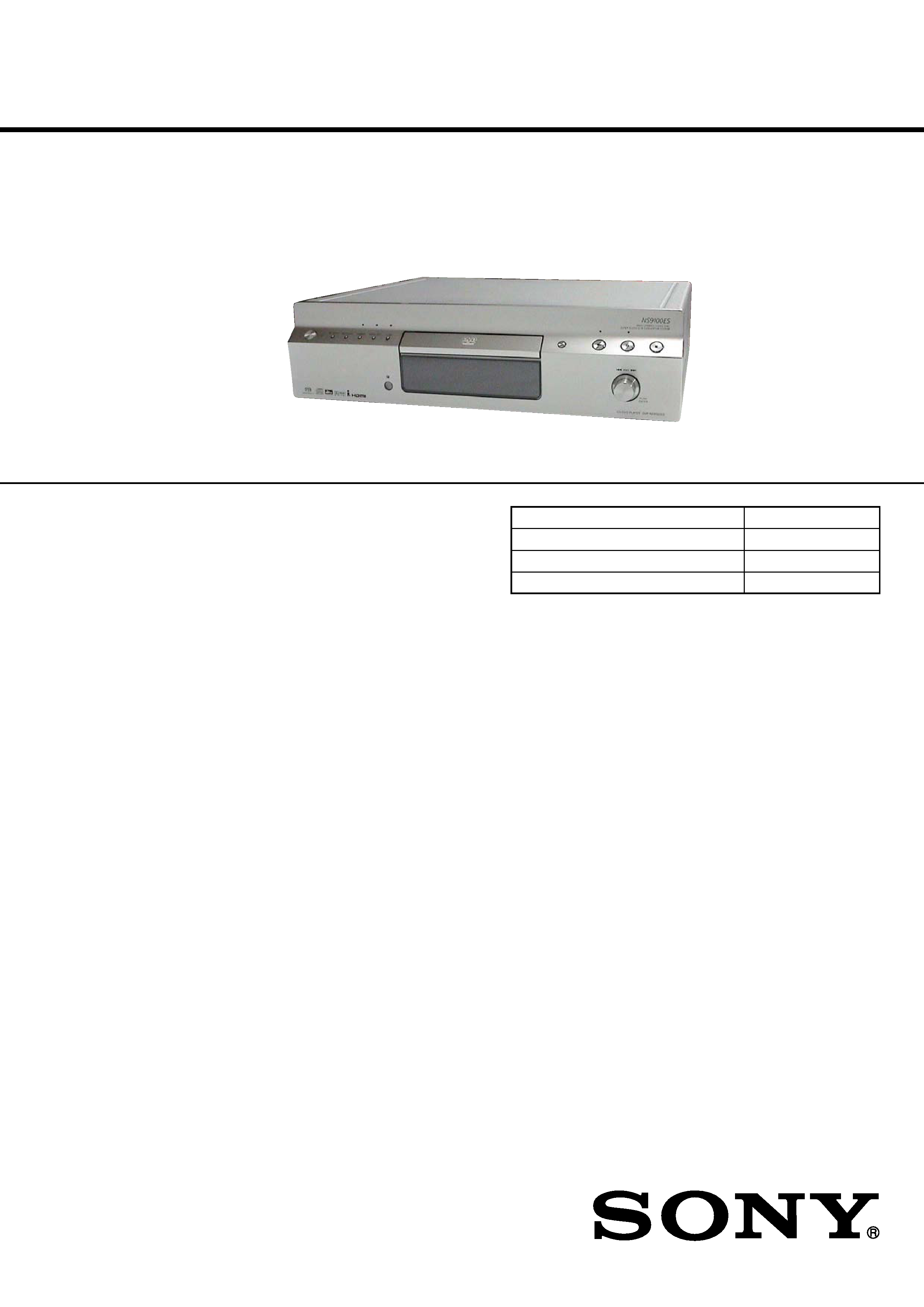
DVP-NS9100ES
Ver. 1.0 2005.08
SPECIFICATIONS
9-879-852-01
2005H05-1
© 2005.08
Sony Corporation
Audio Group
Published by Sony Engineering Corporation
Model Name Using Similar Mechanism
DVP-NS3100ES
CD/DVD Mechanism Type
CDM66DB-DVBU66
Base Unit Name
DVBU66
Optical Traverse Unit Name
DBU-3
* Manufactured under license from Dolby
Laboratories. "Dolby," "Pro Logic," and the
double-D symbol are trademarks of Dolby
Laboratories.
** "DTS" and "DTS Digital Surround" are
registered trademarks of Digital Theater
Systems, Inc.
System
Laser: Semiconductor laser
= 780 nm for CD
= 650 nm for Super Audio CD and
DVD
Emission duration: continuous
Signal format system:
NTSC (US, CND, KR models)
PAL (NTSC) (AEP, UK, RU, CH models)
Audio characteristics
Frequency response: DVD VIDEO (PCM
96 kHz): 2 Hz to 44 kHz (44 kHz: 2 dB
±1 dB), Super Audio CD: 2 Hz to
100 kHz (50 kHz: 3 dB
±1dB), CD:
2Hz to 20 kHz (
±0.5 dB)
Signal-to-noise ratio (S/N ratio): 112 dB
Harmonic distortion: Super Audio CD:
0.0008 %, CD: 0.0015 %
Dynamic range: DVD VIDEO: 115 dB,
Super Audio CD: 108 dB, CD: 100 dB
Wow and flutter: Less than detected value
(
±0.001% W PEAK)
Outputs
(Jack name: Jack type/Output level/Load
impedance)
AUDIO OUT L/R 1/2: Phono jack/2 Vrms/
10 kilohms
DIGITA L OUT (OPTICAL): Optical
output jack/18 dBm (wave length:
660 nm)
HDMI OUT: TypeA (19 pin)
5.1CH OUTPUT: Phono jack/2 Vrms/
10 kilohms
COMPONENT VIDEO OUT(Y, PB/CB,
PR/CR):
Phono jack/Y: 1.0 Vp-p/PB/CB, PR/CR:
interlace1) = 0.648 Vp-p, progressive or
interlace2) = 0.7 Vp-p/75 ohms
1) BLACK LEVEL (COMPONENT
OUT) is ON
2) BLACK LEVEL (COMPONENT
OUT) is OFF
i.LINK S200 (AUDIO) 1/2: 4-pin
Maximum data transmission speed:
200 Mbps
General
Power requirements:
VIDEO OUT 1/2: (US, CND, KR, CH models)
(AEP, UK, RU models)
VIDEO OUT:
S VIDEO OUT 1/2: (US, CND, KR, CH models)
S VIDEO OUT: (AEP, UK, RU models)
120 V AC, 60 Hz (US, CND models)
220 V AC, 60 Hz (KR, CH models)
230 V AC, 50/60 Hz (AEP, UK, RU models)
Power consumption:
38 W (US, CND models)
36 W (AEP, UK, RU, KR, CH models)
0.1 W (at the Power Saving Mode)
Mass (approx.):
10 kg (22 lb) (US, CND, KR, CH models)
10.5 kg (AEP, UK, RU models)
Operating temperature: 5
°C to 35 °C
(41
°F to 95 °F)
Operating humidity: 25 % to 80 %
Dimensions (approx.): 430
× 125 × 390 mm
(17
× 5 × 153/8 in.) (width/height/depth)
incl. projecting parts
Supplied accessories
Specifications and design are subject to
change without notice.
·Audio/video cord
(pinplug
× 3 y pinplug × 3) (1)
·Remote commander (remote) (1)
·Size AA (R6) batteries (2)
·AC power cord (1)
DIGITAL OUT (COAXIAL): Phono jack/
0.5 Vp-p/75 ohms
Phono jack/1.0 Vp-p/75 ohms
4-pin mini DIN/Y: 1.0 Vp-p/C: 0.286 Vp-p
(NISC), 0.3 Vp-p (PAL) /75 ohms
·Abbreviation
CH
: Chinese model
CND : Canadian model
KR
: Korean model
RU
: Russian model
2
DVP-NS9100ES
Notes on chip component replacement
· Never reuse a disconnected chip component.
· Notice that the minus side of a tantalum capacitor may be
damaged by heat.
Flexible Circuit Board Repairing
· Keep the temperature of the soldering iron around 270 °C
during repairing.
· Do not touch the soldering iron on the same conductor of the
circuit board (within 3 times).
· Be careful not to apply force on the conductor when soldering
or unsoldering.
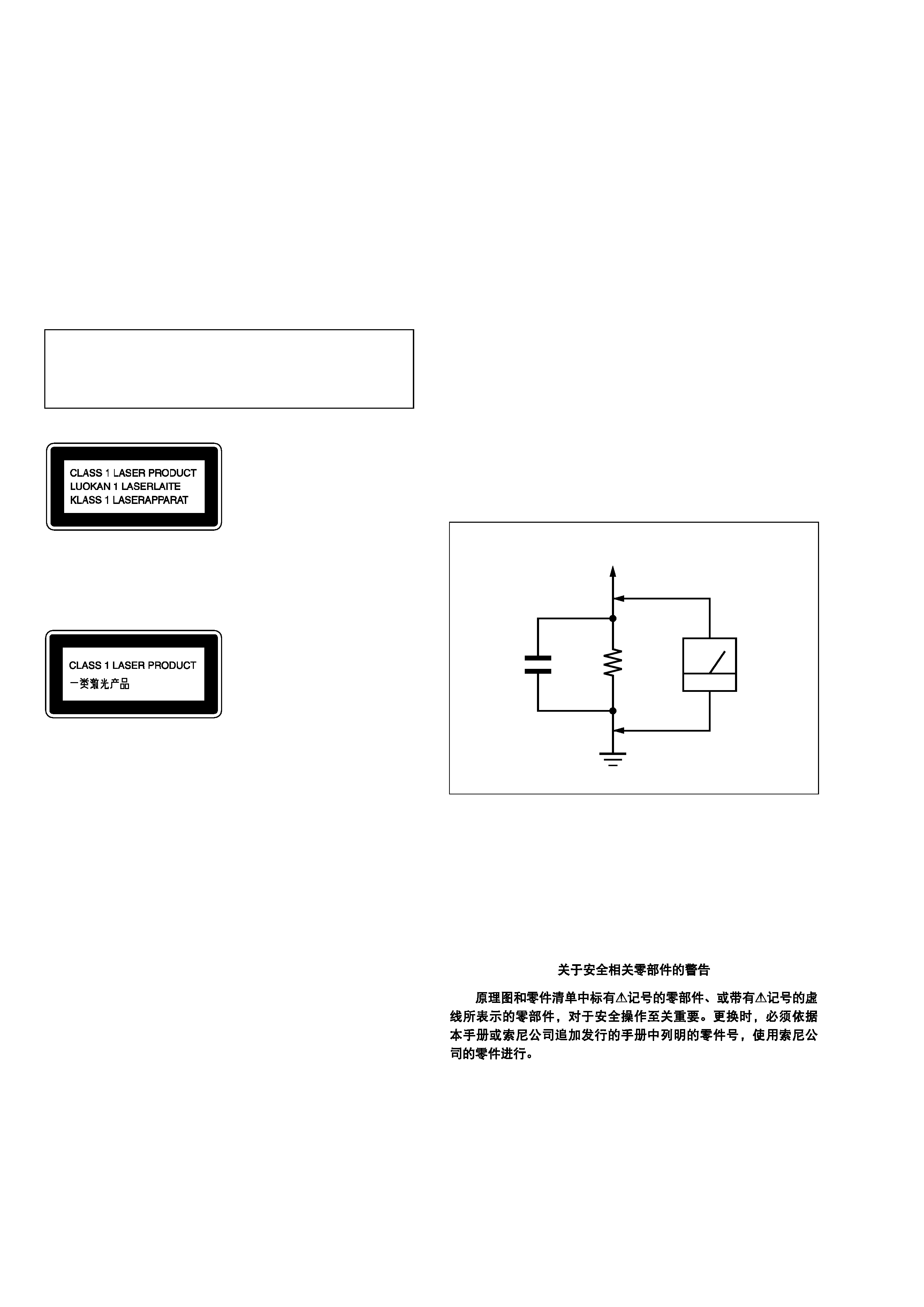
CAUTION
Use of controls or adjustments or performance of procedures
other than those specified herein may result in hazardous radiation
exposure.
SAFETY-RELATED COMPONENT WARNING!!
COMPONENTS IDENTIFIED BY MARK 0 OR DOTTED LINE
WITH MARK 0 ON THE SCHEMATIC DIAGRAMS AND IN
THE PARTS LIST ARE CRITICAL TO SAFE OPERATION.
REPLACE THESE COMPONENTS WITH SONY PARTS WHOSE
PART NUMBERS APPEAR AS SHOWN IN THIS MANUAL OR
IN SUPPLEMENTS PUBLISHED BY SONY.
SAFETY CHECK-OUT
After correcting the original service problem, perform the following
safety check before releasing the set to the customer:
Check the antenna terminals, metal trim, "metallized" knobs, screws,
and all other exposed metal parts for AC leakage.
Check leakage as described below.
LEAKAGE TEST
The AC leakage from any exposed metal part to earth ground and
from all exposed metal parts to any exposed metal part having a
return to chassis, must not exceed 0.5 mA (500 microamperes.).
Leakage current can be measured by any one of three methods.
1. A commercial leakage tester, such as the Simpson 229 or RCA
WT-540A. Follow the manufacturers' instructions to use these
instruments.
2. A battery-operated AC milliammeter. The Data Precision 245
digital multimeter is suitable for this job.
3. Measuring the voltage drop across a resistor by means of a
VOM or battery-operated AC voltmeter. The "limit" indication
is 0.75 V, so analog meters must have an accurate low-voltage
scale. The Simpson 250 and Sanwa SH-63Trd are examples
of a passive VOM that is suitable. Nearly all battery operated
digital multimeters that have a 2 V AC range are suitable. (See
Fig. A)
Fig. A.
Using an AC voltmeter to check AC leakage.
1.5 k
0.15
µF
AC
voltmeter
(0.75 V)
To Exposed Metal
Parts on Set
Earth Ground
ATTENTION AU COMPOSANT AYANT RAPPORT
À LA SÉCURITÉ!
LES COMPOSANTS IDENTIFIÉS PAR UNE MARQUE 0 SUR
LES DIAGRAMMES SCHÉMATIQUES ET LA LISTE DES
PIÈCES
SONT
CRITIQUES
POUR
LA
SÉCURITÉ
DE
FONCTIONNEMENT. NE REMPLACER CES COM- POSANTS
QUE PAR DES PIÈCES SONY DONT LES NUMÉROS SONT
DONNÉS DANS CE MANUEL OU DANS LES SUPPLÉMENTS
PUBLIÉS PAR SONY.
This appliance is classified as a CLASS 1 LASER product.
The CLASS 1 LASER PRODUCT MARKING is located on
the rear exterior.
3
DVP-NS9100ES
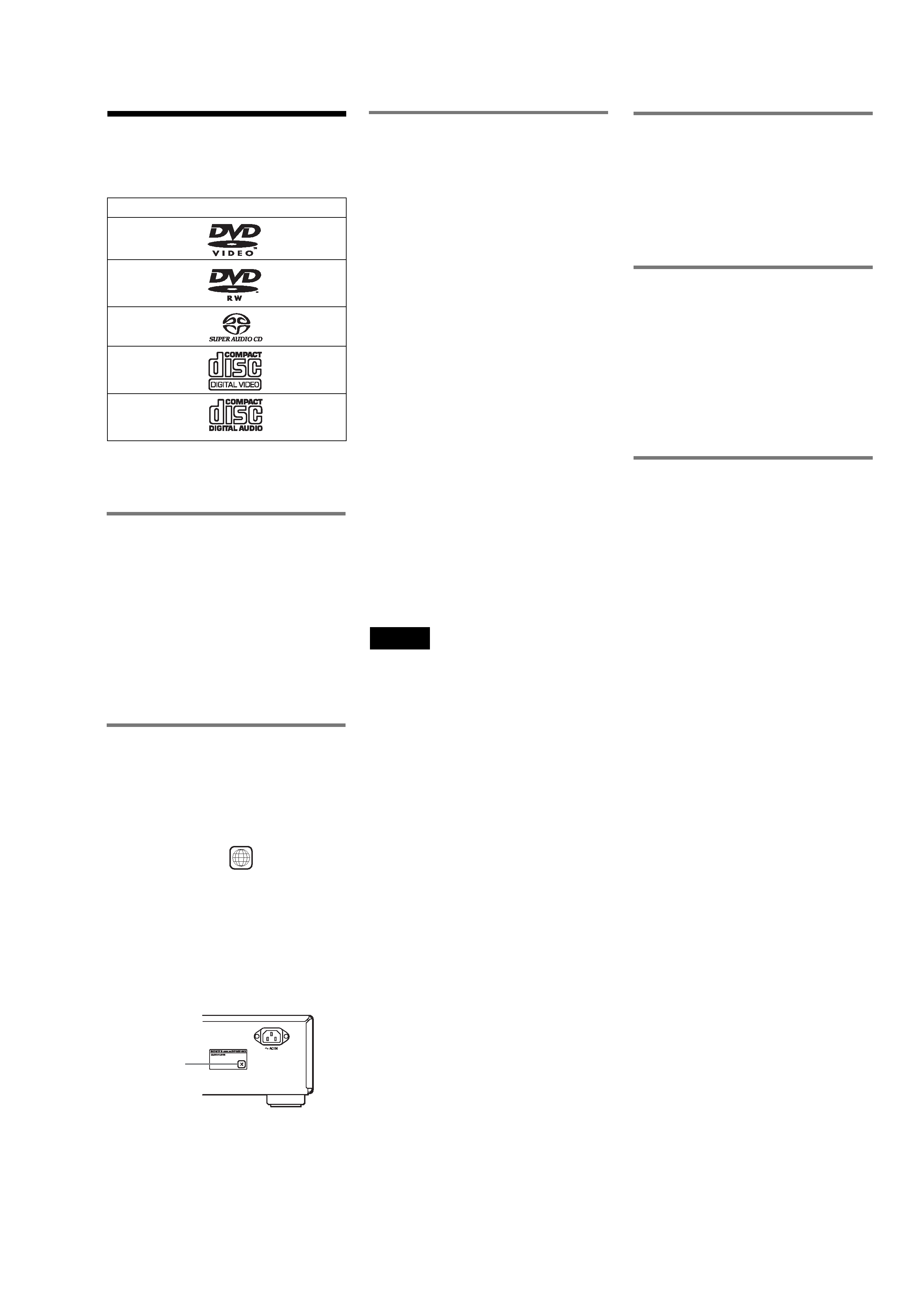
This Player Can Play the
Following Discs
"DVD VIDEO" and "DVD-RW" are
trademarks.
Note about CDs
The player can play CD-ROMs/CD-Rs/CD-
RWs recorded in the following formats:
music CD format
video CD format
MP3 audio tracks and JPEG image files of
format conforming to ISO 9660* Level 1/
Level 2, or its extended format, Joliet
KODAK Picture CD format
*A logical format of files and folders on CD-
ROMs, defined by ISO (International
Organization for Standardization).
Region code
Your player has a region code printed on the
back of the unit and will only play DVD
VIDEOs (playback only) labeled with
identical region codes. This system is used to
protect copyrights.
DVD VIDEOs labeled
will also play on
this player.
Format of discs
DVD VIDEO
DVD-RW
Super Audio CD
VIDEO CD
Music CD
ALL
If you try to play any other DVD VIDEO, the
message "Playback prohibited by area
limitations." will appear on the TV screen.
Depending on the DVD VIDEO, no region
code indication may be labeled even though
playing the DVD VIDEO is prohibited by
area restrictions.
Example of discs that the player
cannot play
The player cannot play the following discs:
·CD-ROMs/CD-Rs/CD-RWs other than
those recorded in the format listed on the
previous page.
·Data part of CD-Extras
·DVD-ROMs
·DVD Audios
Also, the player cannot play the following
discs:
·A DVD VIDEO with a different region
code.
·A disc recorded in a colour system other
than PAL or NTSC, such as SECAM (this
player conforms to the PAL/NTSC colour
system).
·A disc that has a non-standard shape (e.g.,
card, heart).
·A disc with paper or stickers on it.
·A disc that has the adhesive of cellophane
tape or a sticker still left on it.
·DVD-Rs recorded in VR mode (Video
Recording format)
·Copy-Once programmes recorded on
CPRM* compatible DVD-Rs.
*CPRM; Content Protection for Recordable Media
is a coding technology that protects copyright for
Copy-Once programmes.
Notes
· Notes about DVD+RWs/DVD+Rs, DVD-RWs/
DVD-Rs or CD-Rs/CD-RWs
Some DVD+RWs/DV D+Rs, DVD-RWs/DVD-
Rs or CD-Rs/CD-RWs cannot be played on this
player due to the recording quality or physical
condition of the disc, or the characteristics of the
recording device and authoring software.
The disc will not play if it has not been correctly
finalized. For more information, see the operating
instructions for the recording device. Note that
some playback functions may not work with some
DVD+RWs/DVD+Rs, even if they have been
correctly finalized. In this case, view the disc by
normal playback. Also some DATA CDs created
in Packet Write format cannot be played.
·Music discs encoded with copyright protection
technologies
This product is designed to playback discs that
conform to the Compact Disc (CD) standard.
Recently, various music discs encoded with
copyright protection technologies are marketed
by some record companies. Please be aware that
among those discs, there are some that do not
conform to the CD standard and may not be
playable by this product.
Note on DualDiscs
A DualDisc is a two sided disc product which
mates DVD recorded material on one side
with digital audio material on the other side.
However, since the audio material side does
not conform to the Compact Disc (CD)
standard, playback on this product is not
guaranteed.
Note on playback operations of
DVDs and VIDEO CDs
Some playback operations of DVDs and
VIDEO CDs may be intentionally set by
software producers. Since this player plays
DVDs and VIDEO CDs according to the disc
contents the software producers designed,
some playback features may not be available.
Also, refer to the instructions supplied with
the DVDs or VIDEO CDs.
Copyrights
This product incorporates copyright
protection technology that is protected by
U.S. patents and other intellectual property
rights. Use of this copyright protection
technology must be authorized by
Macrovision, and is intended for home and
other limited viewing uses only unless
otherwise authorized by Macrovision.
Reverse engineering or disassembly is
prohibited.
Region code

4
DVP-NS9100ES
TABLE OF CONTENTS
1.
SERVICING NOTES ..............................................
5
2.
GENERAL .................................................................. 10
3.
DISASSEMBLY
3-1.
Disassembly Flow .......................................................... 12
3-2.
Case ................................................................................ 12
3-3.
Front Panel Section ........................................................ 13
3-4.
Mechanism Deck (CDM66DB-DVBU66) .................... 13
3-5.
Base Unit (DVBU66) ..................................................... 14
3-6.
Optical Traverse Unit (DBU-3) ...................................... 14
4.
SERVICE MODE ..................................................... 15
5.
TEST MODE ............................................................. 16
6.
ELECTRICAL ADJUSTMENTS ........................ 24
7.
DIAGRAMS
7-1.
Block Diagram SERVO Section ............................... 27
7-2.
Block Diagram AUDIO Section (1/2) ...................... 28
7-3.
Block Diagram AUDIO Section (2/2) ...................... 29
7-4.
Block Diagram I.LINK Section ................................ 30
7-5.
Block Diagram VIDEO Section (1/2) ...................... 31
7-6.
Block Diagram
VIDEO Section (2/2) (AEP, UK, RU models) ......... 32
7-7.
Block Diagram PANEL Section ............................... 33
7-8.
Block Diagram POWER SUPPLY Section .............. 34
7-9.
Printed Wiring Board BU Board .............................. 36
7-10. Schematic Diagram BU Board ................................. 37
7-11. Printed Wiring Boards MAIN Section (1/2) ............. 38
7-12. Printed Wiring Board MAIN Section (2/2) .............. 39
7-13. Schematic Diagram MAIN Section (1/15) ............... 40
7-14. Schematic Diagram MAIN Section (2/15) ............... 41
7-15. Schematic Diagram MAIN Section (3/15) ............... 42
7-16. Schematic Diagram MAIN Section (4/15) ............... 43
7-17. Schematic Diagram MAIN Section (5/15) ............... 44
7-18. Schematic Diagram MAIN Section (6/15) ............... 45
7-19. Schematic Diagram MAIN Section (7/15) ............... 46
7-20. Schematic Diagram MAIN Section (8/15) ............... 47
7-21. Schematic Diagram MAIN Section (9/15) ............... 48
7-22. Schematic Diagram MAIN Section (10/15) ............. 49
7-23. Schematic Diagram MAIN Section (11/15) ............. 50
7-24. Schematic Diagram MAIN Section (12/15) ............. 51
7-25. Schematic Diagram MAIN Section (13/15) ............. 52
7-26. Schematic Diagram MAIN Section (14/15) ............. 53
7-27. Schematic Diagram MAIN Section (15/15) ............. 54
7-28. Printed Wiring Board
AUDIO Board (Component Side) ............................ 56
7-29. Printed Wiring Board
AUDIO Board (Conductor Side) .............................. 57
7-30. Schematic Diagram AUDIO Board (1/4) ................. 58
7-31. Schematic Diagram AUDIO Board (2/4) ................. 59
7-32. Schematic Diagram AUDIO Board (3/4) ................. 60
7-33. Schematic Diagram AUDIO Board (4/4) ................. 61
7-34. Printed Wiring Board
VIDEO Board (Component Side)
(US, CND, KR, CH models) .......................................... 62
7-35. Printed Wiring Board
VIDEO Board (Conductor Side)
(US, CND, KR, CH models) .......................................... 63
7-36. Schematic Diagram
VIDEO Board (1/2) (US, CND, KR, CH models) ... 64
7-37. Schematic Diagram
VIDEO Board (2/2) (US, CND, KR, CH models) ... 65
7-38. Printed Wiring Board
VIDEO Board (Component Side)
(AEP, UK, RU models) .................................................. 66
7-39. Printed Wiring Board
VIDEO Board (Conductor Side)
(AEP, UK, RU models) .................................................. 67
7-40. Schematic Diagram
VIDEO Board (1/2) (AEP, UK, RU models) ............ 68
7-41. Schematic Diagram
VIDEO Board (2/2) (AEP, UK, RU models) ............ 69
7-42. Printed Wiring Board DISPLAY Board ................... 70
7-43. Schematic Diagram DISPLAY Board ...................... 71
7-44. Printed Wiring Boards KEY Section ........................ 72
7-45. Schematic Diagram KEY Section ............................ 73
7-46. Printed Wiring Board RS232C Board ...................... 74
7-47. Schematic Diagram RS232C Board ......................... 75
7-48. Printed Wiring Board POWER2 Board .................... 76
7-49. Schematic Diagram POWER2 Board ....................... 77
7-50. Printed Wiring Board
POWER1 Board (Component Side) ......................... 78
7-51. Printed Wiring Board
POWER1 Board (Conductor Side) ........................... 79
7-52. Schematic Diagram POWER1 Board ....................... 80
8.
EXPLODED VIEWS
8-1.
Case Section ................................................................... 115
8-2.
Display Board Section .................................................... 116
8-3.
Front Panel Section ........................................................ 117
8-4.
Video Board Section (US, CND, KR, CH models) ........ 118
8-5.
Video Board Section (AEP, UK, RU models) ................ 119
8-6.
Chassis Section ............................................................... 120
8-7.
Mechanism Deck Section (CDM66DB-DVBU66) ........ 121
8-8.
Base Unit Section (DVBU66) ........................................ 122
9.
ELECTRICAL PARTS LIST ............................... 123
· Abbreviation
CH
: Chinese model
CND : Canadian model
KR
: Korean model
RU
: Russian model
5
DVP-NS9100ES
NOTES ON REPLACEMENT OF THE MAIN BOARD
1. Flash Memory
New part of flash memory (IC253, IC801) on the MAIN board
cannot be used. Therefore, if the mounted MAIN board is replaced,
exchange new flash memory with that used before the replacement.
2. Adjustment
When replacing the MAIN board, since the adjustment value is not
set up correctly, "Drive Auto Adjustment" in the Test Mode can't
be performed.
In this case, initialize memory in the following procedures.
Procedure:
1. Connect a video monitor to VIDEO OUT jack (J502).
2. Press the [TOP MENU], [CLEAR], I/1 keys on the remote
commander (RM-ASP003 or RM-ASP004) in this order with
standby status to enter the Test Mode, then "DIAG START"
will be displayed on the fluorescent indicator tube and the
Test Mode Menu screen will be displayed on the monitor.
3. Press the [2] key on the remote commander to select the "2.
Drive Manual Operation".
4. Press the [6] key on the remote commander to select the "6.
Memory Check".
5. Press the [CLEAR] key on the remote commander to initialize
the memory.
Note: Refer to page 17 for detail of the Test Mode
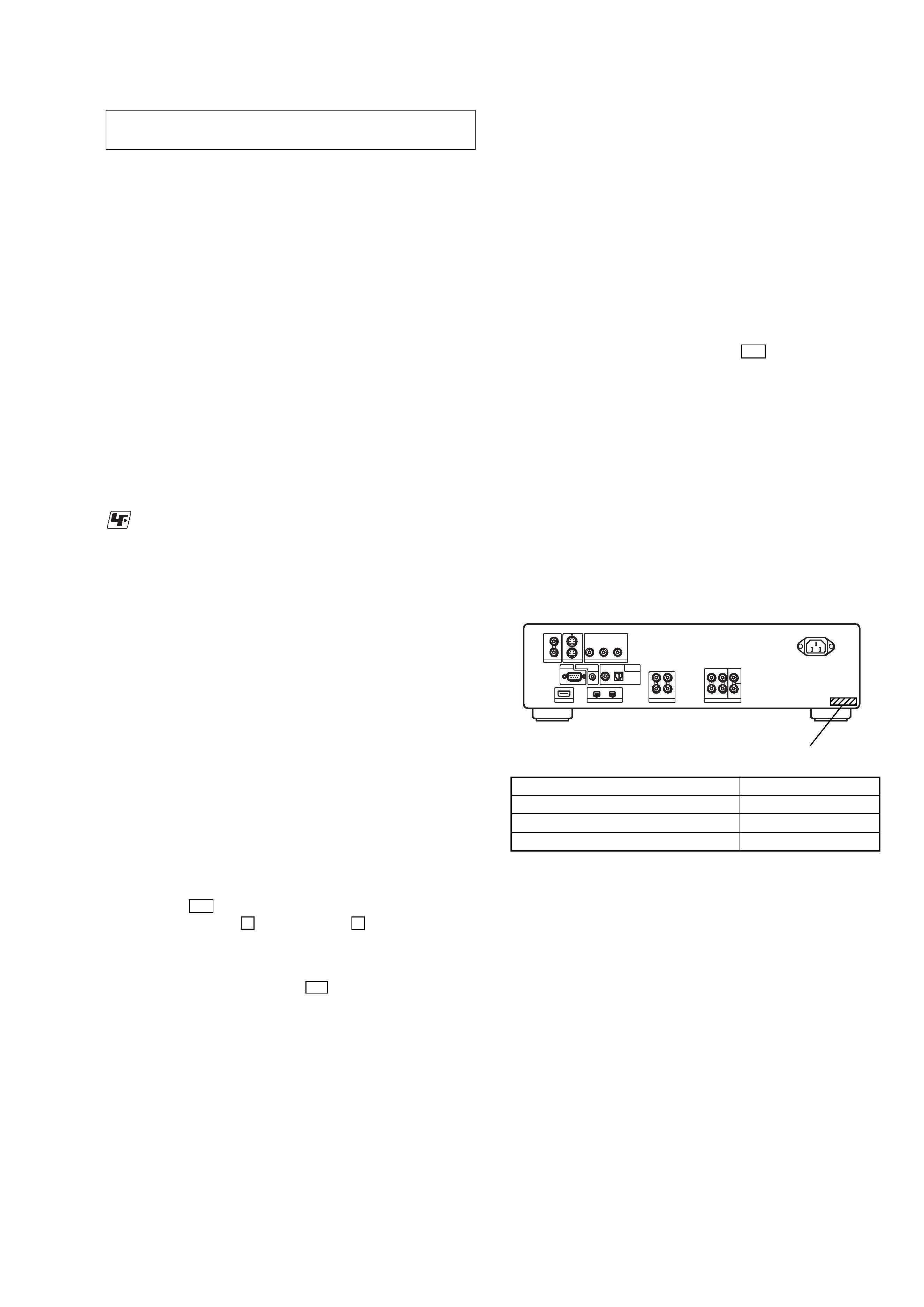
MODEL IDENTIFICATION
Back Panel
MODEL
PART No.
US, Korean and Chinese models
2-546-946-0[]
Canadian model
2-546-946-1[]
AEP, UK and Russian models
2-546-946-2[]
SECTION 1
SERVICING NOTES
The laser diode in the optical pick-up block may suffer electrostatic
break-down because of the potential difference generated by the
charged electrostatic load, etc. on clothing and the human body.
During repair, pay attention to electrostatic break-down and also
use the procedure in the printed matter which is included in the
repair parts.
The flexible board is easily damaged and should be handled with
care.
NOTES ON LASER DIODE EMISSION CHECK
The laser beam on this model is concentrated so as to be focused on
the disc reflective surface by the objective lens in the optical pick-
up block. Therefore, when checking the laser diode emission,
observe from more than 30 cm away from the objective lens.
UNLEADED SOLDER
Boards requiring use of unleaded solder are printed with the lead-
free mark (LF) indicating the solder contains no lead.
(Caution: Some printed circuit boards may not come printed with
the lead free mark due to their particular size)
: LEAD FREE MARK
Unleaded solder has the following characteristics.
· Unleaded solder melts at a temperature about 40 °C higher
than ordinary solder.
Ordinary soldering irons can be used but the iron tip has to be
applied to the solder joint for a slightly longer time.
Soldering irons using a temperature regulator should be set to
about 350
°C.
Caution: The printed pattern (copper foil) may peel away if
the heated tip is applied for too long, so be careful!
· Strong viscosity
Unleaded solder is more viscou-s (sticky, less prone to flow)
than ordinary solder so use caution not to let solder bridges
occur such as on IC pins, etc.
· Usable with ordinary solder
It is best to use only unleaded solder but unleaded solder may
also be added to ordinary solder.
RELEASING THE TRAY LOCK
The disc tray lock function for the antitheft of an demonstration
disc in the store is equipped.
Releasing Procedure :
1. Press the I/1 button to turn the power on.
2. While pressing the x button, press the A button until "TRAY
UNLOCKED" displayed on the FL tube (around 5 seconds).
Note: When "TRAY LOCKED" is displayed, the tray lock is not released
by turning power on/off with the I/1 button.
NOTES ON HANDLING THE OPTICAL PICK-UP
BLOCK OR BASE UNIT
PART No.