SERVICE MANUAL
AEP Model
DVP-NS355/NS360
UK Model
Russian Model
DVP-NS355
CD/DVD PLAYER
DVP-NS355/NS360
RMT-D165P/D166P
The Service Manual for this set contains only the points which differ is
bound together with the following Service Manual and therefore please
refer to them.
DVP-NS355: Brazilian
DVP-NS355: AEP, UK, RUS/DVP-NS360: AEP
See next page for different part.
· Main Unit
DVP-NS355/NS507P/NS525P/NS575P/NS585P
9-874-811-11
Service Manual
Differences Manual
· DIFFERENT PARTS LIST
8-1. EXPLODED VIEWS
8-1-1. MAIN SECTION
2
A-1062-809-A MV-044 COMPL (NS355: RUS)
2
A-6071-901-A MV-044 COMPL
(NS355: AEP, UK/NS360: AEP)
0 4
1-478-540-31 POWER SUPPLY BLOCK
5
X-3954-062-2 PANEL, ASSY FRONT (NS355: AEP, RUS)
(BLACK)
5
X-3954-063-2 PANEL, ASSY FRONT
(NS355: AEP, UK, RUS) (SILVER)
5
X-3954-208-2 PANEL, ASSY FRONT (NS360: AEP)
(SILVER)
6
3-066-225-01 SONY BADGE (5-A) (NS355: AEP, RUS)
(BLACK)
6
3-066-225-11 SONY BADGE (5-A)
(NS355: AEP, UK, RUS/NS360: AEP)
(SILVER)
Page
NS355: Brazilian model
NS355: AEP, UK, RUS/NS360: AEP model
Ref. No.
Part No.
Description
Remarks
Ref. No.
Part No.
Description
Remarks
2
A-6072-189-A MV-044 COMPL
0 4
1-478-539-11 POWER SUPPLY BLOCK
5
A-6072-191-A PANEL, ASSY FRONT
6
3-066-225-41 SONY BADGE (5-A)
8-1
The components identified by mark
0 or dotted line with mark 0 are
critical for safety.
Replace only with part number speci-
fied.
·Abbreviation
RUS: Russian model
Continued on next page
2
DVP-NS355/NS360
Sony Corporation
Home Electronics Network Company
9-874-815-11
2004B0500-1
© 2004. 2
Published by Quality Assurance Dept.
Page
NS355: Brazilian model
NS355: AEP, UK, RUS/NS360: AEP model
Ref. No.
Part No.
Description
Remarks
Ref. No.
Part No.
Description
Remarks
8-1
8-2. ELECTRICAL PARTS LIST
A-1062-809-A MV-044 BOARD, COMPLETE (NS355: RUS)
A-6071-901-A MV-044 BOARD, COMPLETE
(NS355: AEP, UK/NS360: AEP)
***********************
Page
NS355: Brazilian model
NS355: AEP, UK, RUS/NS360: AEP model
Ref. No.
Part No.
Description
Remarks
Ref. No.
Part No.
Description
Remarks
A-6072-189-A MV-044 BOARD, COMPLETE
***********************
8-9
8
3-088-330-51 COVER, TRAY
0 11
1-828-450-11 POWER-SUPPLY CORD
12
3-070-883-41 SCREW, TAPPING
13
3-088-344-42 CASE, UPPER (SILVER)
15
1-478-545-11 REMOTE COMMANDER (RMT-D165A)
16
3-071-119-11 COVER, BATTERY
ACCESSORIES
************
1-824-933-21 CORD WITH CONNECTOR
3-091-941-11 MANUAL, INSTRUCTION
8
3-088-330-31 COVER, TRAY
0 11
1-828-450-11 POWER-SUPPLY CORD
(EXCEPT NS355: UK)
11
1-828-454-11 POWER-SUPPLY CORD (NS355: UK)
12
3-070-883-31 SCREW, TAPPING (NS355: AEP, RUS)
(BLACK)
12
3-070-883-41 SCREW, TAPPING
(NS355: AEP, UK, RUS/NS360: AEP)
(SILVER)
13
3-089-692-01 CASE, UPPER (NS355: AEP, RUS) (BLACK)
13
3-089-692-11 CASE, UPPER
(NS355: AEP, UK, RUS/NS360: AEP)
(SILVER)
15
1-478-545-31 REMOTE COMMANDER (RMT-D165P)
(NS355: AEP, RUS) (BLACK)
15
1-478-545-41 REMOTE COMMANDER (RMT-D166P)
(NS355: AEP, UK, RUS/NS360: AEP)
(SILVER)
16
3-071-119-01 COVER, BATTERY (NS355: AEP, RUS)
(BLACK)
16
3-071-119-11 COVER, BATTERY
(NS355: AEP, UK, RUS/NS360: AEP)
(SILVER)
1-828-427-11 FLAT FLEXIBLE CABLE FEM-002
ACCESSORIES
************
1-824-933-21 CORD WITH CONNECTOR (NS355: UK)
3-089-857-11 MANUAL, INSTRUCTION
(GERMAN, FRENCH, DUTCH)
(NS355: AE1/NS360: AE1)
3-089-857-21 MANUAL, INSTRUCTION
(ITALIAN, POLISH)
(NS355: AE1/NS360: AE1)
3-089-857-31 MANUAL, INSTRUCTION
(SPANISH, GREEK, PORTUGUESE)
(NS355: AE2/NS360: AE2)
3-089-857-41 MANUAL, INSTRUCTION
(DANISH, FINNISH, SWEDISH)
(NS355: AE2/NS360: AE2)
3-089-857-51 MANUAL, INSTRUCTION (ENGLISH)
(NS355: UK)
3-089-857-61 MANUAL, INSTRUCTION (RUSSIAN)
(NS355: RUS)
The components identified by mark
0 or dotted line with mark 0 are
critical for safety.
Replace only with part number speci-
fied.
·Abbreviation
RUS: Russian model
RMT-D165A/RMT-D165P/RMT-D166P
SERVICE MANUAL
CD/DVD PLAYER
System
Laser: Semiconductor laser
Signal format system: NTSC
Audio characteristics
Frequency response: DVD VIDEO (PCM
96 kHz): 2 Hz to 44 kHz (±1.0 dB)/
DVD VIDEO (PCM 48 kHz): 2 Hz to
22 kHz (±0.5 dB)/CD: 2 Hz to 20 kHz
(±0.5 dB)
Signal-to-noise ratio (S/N ratio): 115 dB
Harmonic distortion: 0.003%
Dynamic range: DVD VIDEO: 103 dB/
CD: 99 dB
Wow and flutter: Less than detected value
(±0.001% W PEAK)
Outputs
(Jack name: Jack type/Output level/
Load impedance)
LINE OUT (AUDIO): Phono jack/
2 Vrms/ 10 kilohms
DIGITAL OUT (COAXIAL): Phono jack/
0.5 Vp-p/75 ohms
COMPONENT VIDEO OUT
(Y, PB, PR): Phono jack/Y: 1.0 Vp-p/
PB, PR: 0.65 Vp-p/75 ohms
LINE OUT (VIDEO): Phono jack/
1.0 Vp-p 75 ohms
S VIDEO OUT: 4-pin mini DIN/Y:
1.0 Vp-p, C: 0.286 Vp-p/75 ohms
General
Power requirements:
120 V AC, 60 Hz
110-240 V AC, 50/60 Hz
See page 5 for further information
Power consumption: 11 W
Dimensions (approx.): 430
× 43 ×
237.7 mm (17
× 2 11/16 × 9 1/2 in.)
(width/height/depth) incl. projecting
parts
Mass (approx.): 1.95 kg (4 1/3 lb)
Operating temperature: 5°C to 35°C
(41°F to 95°F)
Operating humidity: 25% to 80%
SPECIFICATIONS
Supplied accessories
See page 17
Specifications and design are subject to
change without notice.
ENERGY STAR is a U.S. registered
mark.
As an
ENERGY STAR Partner, Sony
Corporation has determined that this
product meets the
ENERGY STAR
guidelines for energy efficiency.
Canada Model
PX Model
Mexico Model
Latin Model
Brazil Model
Hong Kong Model
GA Model
Taiwan Model
Korea Model
Saudi Arabia Model
Middle East Model
India Model
Australia Model
China Model
Argentina Model
US Model
Iran Model
DVP-NS575P
DVP-NS355/NS501P/NS507P/NS525P/NS575P/NS585P
Notes: US and Canada model only
Photo : DVP-NS575P
RMT-D165P
Brazil Model
DVP-NS355
China Model
DVP-NS507P/NS525P/NS585P
Middle East Model
DVP-NS585P
US Model
DVP-NS501P
2
SAFETY CHECK-OUT
1. Check the area of your repair for unsoldered or poorly-soldered
connections. Check the entire board surface for solder splashes
and bridges.
2. Check the interboard wiring to ensure that no wires are "pinched"
or contact high-wattage resistors.
3. Look for unauthorized replacement parts, particularly transis-
tors, that were installed during a previous repair. Point them out
to the customer and recommend their replacement.
4. Look for parts which, though functioning, show obvious signs
of deterioration. Point them out to the customer and recommend
their replacement.
5. Check the line cord for cracks and abrasion.
Recommend the replacement of any such line cord to the cus-
tomer.
6. Check the B+ voltage to see it is at the values specified.
7. Check the antenna terminals, metal trim, "metallized" knobs,
screws, and all other exposed metal parts for AC leakage. Check
leakage as described below.
WARNING!!
WHEN SERVICING, DO NOT APPROACH THE LASER EXIT
WITH THE EYE TOO CLOSELY. IN CASE IT IS NECESSARY TO
CONFIRM LASER BEAM EMISSION, BE SURE TO OBSERVE
FROM A DISTANCE OF MORE THAN 25 cm FROM THE SURFACE
OF THE OBJECTIVE LENS ON THE OPTICAL PICK-UP BLOCK.
CAUTION:
The use of optical instrument with this product will increase eye
hazard.
CAUTION
Use of controls or adjustments or performance of procedures
other than those specified herein may result in hazardous radiation
exposure.
SAFETY-RELATED COMPONENT WARNING!!
COMPONENTS IDENTIFIED BY MARK
OR DOTTED LINE
WITH MARK
ON THE SCHEMATIC DIAGRAMS AND IN
THE PARTS LIST ARE CRITICAL TO SAFE OPERATION.
REPLACE THESE
COMPONENTS WITH
SONY
PARTS
WHOSE PART NUMBERS APPEAR AS SHOWN IN THIS
MANUAL OR IN SUPPLEMENTS PUBLISHED BY SONY.
After correcting the original service problem, perform the following
safety checks before releasing the set to the customer:
LEAKAGE TEST
The AC leakage from any exposed metal part to earth ground and
from all exposed metal parts to any exposed metal part having a
return to chassis, must not exceed 0.5mA (500 microampers).
Leakage current can be measured by any one of three methods.
1. A commercial leakage tester, such as the Simpson 229 or RCA
TW-540A. Follow the manufacturers' instructions to use these
instruments.
2. A battery-operated AC milliammeter. The Data Precision 245
digital multimeter is suitable for this job.
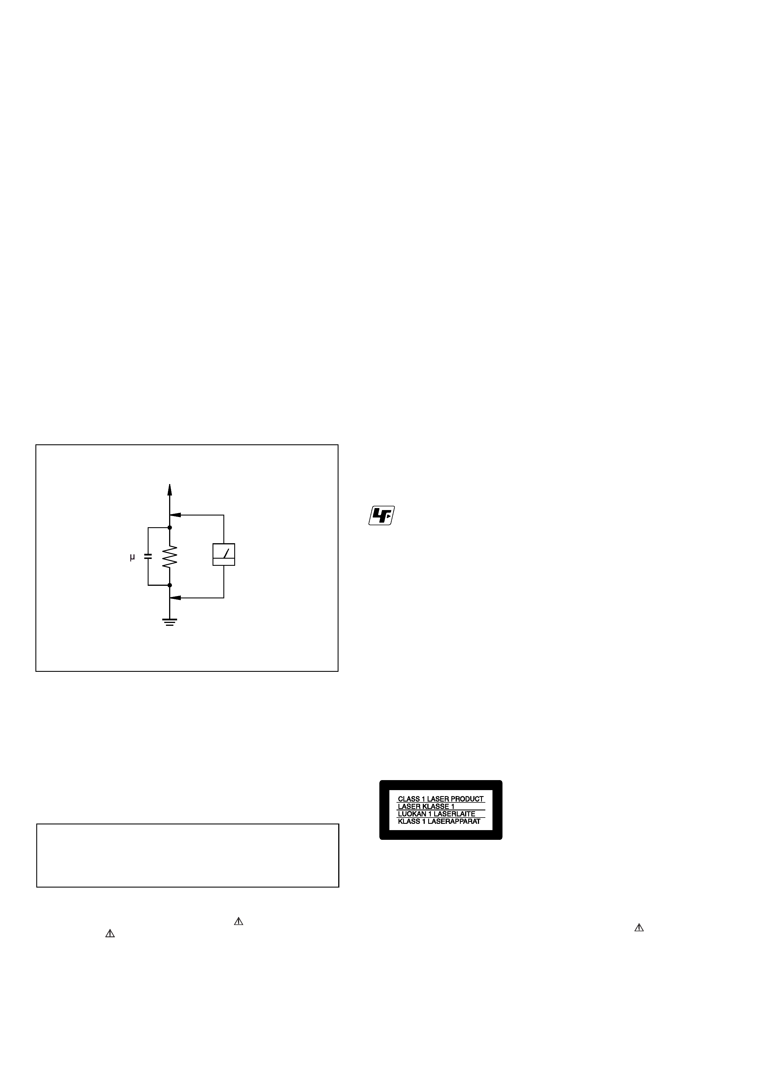
3. Measuring the voltage drop across a resistor by means of a
VOM or battery-operated AC volmeter. The "limit" indication
is 0.75V, so analog meters must have an accurate low voltage
scale. The Simpson 250 and Sanwa SH-63Trd are examples of
a passive VOM that is suitable. Nearly all battery operated
digital multimeters that have a 2V AC range are suitable. (See
Fig. A)
Unleaded solder
Boards requiring use of unleaded solder are printed with the lead-
free mark (LF) indicating the solder contains no lead.
(Caution: Some printed circuit boards may not come printed with
the lead free mark due to their particular size.)
: LEAD FREE MARK
Unleaded solder has the following characteristics.
· Unleaded solder melts at a temperature about 40°C highter than
ordinary solder.
Ordinary soldering irons can be used but the iron tip has to be
applied to the solder joint for a slightly longer time.
Soldering irons using a temperature regulator should be set to
about 350°C
Caution: The printed pattern (copper foil) may peel away if the
heated tip is applied for too long, so be careful!
· Strong viscosity
Unleaded solder is more viscous (sticky, less prone to flow) than
ordinary solder so use caution not to let solder bridges occur such
as on IC pins, etc.
· Usable with ordinary solder
It is best to use only unleaded solder but unleaded solder may also
be added to ordinary solder.
ATTENTION AU COMPOSANT AYANT RAPPORT
À LA SÉCURITÉ!
LES COMPOSANTS IDENTIFÉS PAR UNE MARQUE
SUR
LES DIAGRAMMES SCHÉMATIQUES ET LA LISTE DES PIÈCES
SONT
CRITIQUES
POUR
LA
SÉCURITÉ
DE
FONCTIONNEMENT. NE REMPLACER CES COMPOSANTS
QUE PAR DES PIÈSES SONY DONT LES NUMÉROS SONT
DONNÉS DANS CE MANUEL OU DANS LES SUPPÉMENTS
PUBLIÉS PAR SONY.
To Exposed Metal
Parts on Set
0.15 F
1.5k
AC
Voltmeter
(0.75 V)
Earth Ground
Fig.A. Using an Acvoltmeter to check AC leakage.

3
TABLE OF CONTENTS
SERVICE NOTE
1.
Disc Removal Procedure (at POWER OFF) .............. 4
2.
Caution Point on the PWB IF-112 ................................. 4
1.
GENERAL
Precautions .................................................................... 1-1
About this Manual .......................................................... 1-1
This Player Can Play the Following Discs ................... 1-1
Notes about the Discs .................................................. 1-1
Index to Parts and Controls ......................................... 1-1
Guide to the Control Menu Display .............................. 1-2
Hookups ................................................................................ 1-3
Hooking Up the Player .................................................. 1-3
Step 1: Unpacking ......................................................... 1-3
Step 2: Inserting Batteries into the Remote ................. 1-3
Step 3: Connecting the Video Cords ............................ 1-3
Step 4: Connecting the Audio Cords ............................ 1-4
Step 5: Connecting the Power Cord ............................. 1-5
Step 6: Quick Setup ...................................................... 1-5
Playing Discs ......................................................................... 1-6
Playing Discs ................................................................. 1-6
Resuming Playback from the Point Where You
Stopped the Disc (Multi-disc Resume) .................. 1-6
Using the DVD's Menu .................................................. 1-6
Selecting "ORIGINAL" or "PLAY LIST" on a
DVD-RW DISC ......................................................... 1-6
Playing VIDEO CD's With PBC Functions
(PBC Playback) ........................................................ 1-7
Various Play Mode Functions (Program Play,
Shuffle Play, Repeat Play, A-B Repeat Play ........... 1-7
Searching for a Scene .......................................................... 1-8
Searching for a Particular Point on a Disc (Search,
Scan, Slow-motion Play, Freeze Frame) ............... 1-8
Searching for a Title/Chapter/Track/Scene, etc. ......... 1-8
Searching by Scene (PICTURE NAVIGATION) ......... 1-9
Viewing Information About the Disc ..................................... 1-9
Checking the Playing Time and Remaining Time ........ 1-9
Sound Adjustments ............................................................... 1-10
Changing the Sound ...................................................... 1-10
TV Virtual Surround Settings (TVS) ............................. 1-10
Enjoying Movies .................................................................... 1-11
Changing the Angles ..................................................... 1-11
Displaying the Subtitles ................................................. 1-11
Adjusting the Playback Picture
(CUSTOM PICTURE MODE) ................................. 1-11
Sharpening the Outline of an Image (SHARPNESS) .. 1-11
Playing a DATA CD ............................................................... 1-11
About MP3 Audio Tracks and JPEG Image Files ....... 1-11
Playing DATA CDs with MP3 Audio Tracks and
JPEG Image Files .................................................... 1-12
Specifying the slideshow duration ............................... 1-13
Selecting an effect for image files in the slideshow .... 1-13
Using Various Additional Functions ...................................... 1-13
Locking Discs (CUSTOM PARENTAL CONTROL,
PARENTAL CONTROL) .......................................... 1-13
Controlling Your TV with the Supplied Remote ............. 1-14
Settings and Adjustments ..................................................... 1-15
Using the Setup Display ............................................... 1-15
Setting the Display or Sound Track Language
(LANGUAGE SETUP) ............................................. 1-15
Settings for the Display (SCREEN SETUP) ................ 1-15
Custom Settings (CUSTOM SETUP) .......................... 1-16
Settings for the Sound (AUDIO SETUP) ..................... 1-16
Additional Information ............................................................ 1-16
Troubleshooting ............................................................. 1-16
Self-diagnosis Function (When letters/
numbers appear in the display ................................ 1-17
Glossary ........................................................................ 1-17
Specifications ................................................................. 1-18
2.
DISASSEMBLY
2-1.
Upper Case ................................................................... 2-1
2-2.
Front Panel Assembly ................................................... 2-1
2-3.
Loading Assembly ......................................................... 2-2
2-4.
Optical Device (KHM-310AAA) .................................... 2-3
2-5.
DC Motor and MS-203 Board ....................................... 2-4
2-6.
MV-044 BOARD ............................................................ 2-4
2-7.
Switching Regulator ...................................................... 2-5
2-8.
Interval Views ................................................................. 2-6
2-9.
Circuit Boards Location ................................................. 2-7
3.
BLOCK DIAGRAMS
3-1.
Overall Block Diagram .................................................. 3-1
3-2.
System Control/Signal Processor Block Diagram ...... 3-3
3-3.
RF/Servo Block Diagram .............................................. 3-5
3-4.
Audio Block Diagram ..................................................... 3-7
3-5.
Video Block Diagram ..................................................... 3-9
3-6.
Interface Control Block Diagram .................................. 3-11
3-7.
Power Block Diagram .................................................... 3-13
4.
PRINTED WIRING BOARDS AND
SCHEMATIC DIAGRAMS
4-1.
Frame Schematic Diagram ........................................... 4-1
4-2.
Printed Wiring Boards and Schematic Diagrams ........ 4-3
Waveform ...................................................................... 4-4
·
MV-044 Printed Wiring Board .................................. 4-5
·
MV-044 (Drive) Schematic Diagram ....................... 4-7
·
MV-044 (CPU, Servo-DSP, AVDEC)
Schematic Diagram ............................................ 4-9
·
MV-044 (Video) Schematic Diagram ....................... 4-11
·
MV-044 (Audio) Schematic Diagram ....................... 4-13
·
MV-044 (PS Through) Schematic Diagram ............ 4-15
·
IF-112 Printed Wiring Board .................................... 4-17
·
IF-112 (Interface) Schematic Diagram .................. 4-19
·
Power Block (SRV1487UC)
Printed Wiring Board ........................................... 4-21
·
Power Block (SRV1487UC)
Schematic Diagram ............................................ 4-23
·
Power Block (SRV1501WW)
Printed Wiring Board ........................................... 4-25
·
Power Block (SRV1501WW)
Schematic Diagram ............................................ 4-27
5.
IC PIN FUNCTION DESCRIPTION
5-1.
System Control-Video Pin Function
(MV-044 BOARD IC201) .............................................. 5-1
6.
TEST MODE
6-1.
General Description ...................................................... 6-1
6-2.
Starting Test Mode ........................................................ 6-1
6-3.
Drive Manual Operation ................................................ 6-1
6-4.
Mirror Time Adjustment ................................................. 6-1
6-5.
Executing IOP Measurement ....................................... 6-3
6-6.
If Con Self Diagnostic Function .................................... 6-4
7.
ELECTRICAL ADJUSTMENT
7-1.
Power Supply Adjustment ............................................. 7-1
8.
REPAIR PARTS LIST
8-1.
Exploded Views ............................................................. 8-1
8-1-1. Main Section ............................................................. 8-1
8-1-2. Mechanism Deck Assembly .................................... 8-3
8-2.
Electrical Parts List ....................................................... 8-4