CD/DVD PLAYER
System
Laser: Semiconductor laser
Signal format system:
PAL/NTSC: (NS52P/NS50P
Except US,CND,MX,PX) NTSC:
(NS41P/NS50P:US,CND,MX,PX)
Audio characteristics
Frequency response: DVD VIDEO (PCM
96 kHz): 2 Hz to 44 kHz (±1.0 dB)/
DVD VIDEO (PCM 48 kHz): 2 Hz to
22 kHz (±0.5 dB)/CD: 2 Hz to 20 kHz
(±0.5 dB)
Signal-to-noise ratio (S/N ratio): 115 dB
(LINE OUT L/R (AUDIO) jacks only)
Harmonic distortion:
0.003%
Dynamic range: DVD VIDEO: 103 dB/
CD: 99 dB
Wow and flutter: Less than detected value
(±0.001% W PEAK)
Outputs
(Jack name: Jack type/Output level/
Load impedance)
LINE OUT (AUDIO): Phono jack/
2 Vrms/ 10 kilohms
DIGITAL OUT (OPTICAL)
Optical output jack/18 dBm
(wave length 660 nm) (DVP-NS52P/
NS50P:AUS,SP,TW,HK,ME2,ME5,EA,IR,KR)
DIGITAL OUT (COAXIAL): Phono jack/
0.5 Vp-p/75 ohms
COMPONENT VIDEO OUT
(Y, PB/CB, PR/CR)
Phono jack/Y: 1.0 Vp-p,
PB/CB, PR/CR: 0.7 Vp-p/75 ohms
(NS52P/NS50P Except
US,CND,PX,MX,E)
COMPONENT VIDEO OUT
(YZ, PB, PR)
Phono jack/Y: 1.0 Vp-p/PB,PR:
interface*1 = 0.648 Vp-p, progressive or
interface*2 = 0.7 Vp-p/75 ohms
*1
BLACK LEVEL
(COMPONENT OUT) is ON
*2
BLACK LEVEL
(COMPONENT OUT) is OFF
(NS41P/NS50P:US,CND,PX,MX,E)
LINE OUT (VIDEO): Phono jack/
1.0 Vp-p/75 ohms
S VIDEO OUT
4-pin mini DIN/Y: 1.0 Vp-p,
C: 0.3 Vp-p (PAL), 0.286 Vp-p
(NTSC)/75 ohms (NS52P/NS50P:
Except US,CND,PX,MX)
S VIDEO OUT
4-pin mini DIN/Y: 1.0 Vp-p,
C: 0.286 Vp-p/75 ohms
(NS41P/NS50P:US,CND,PX,MX)
General
Power requirements:
110 V AC, 60 Hz
(NS50P:TW/NS52P:TW)
110 240 V AC, 50/60 Hz
(Except NS41P/NS50P:
US,CND,MX,TW/NS52P:TW)
120 V AC, 60 Hz
(NS41P/NS50P:US,CND,MX)
SPECIFICATIONS
Power consumption: 10 W
Dimensions (approx.):
430
× 43 × 237.2 mm
(17
× 11 11/16 × 9 3/8 in.)
(width/height/depth)
incl. projecting parts
430
× 43 × 237.3 (DVP-NS52P)
Mass (approx.): 1.92 kg (4 1/3 lb)
Operating temperature: 5°C to 35°C
Operating humidity: 25% to 80%
Supplied accessories
See page 14 (Except NS41P/
NS50P:US,CND,PX)
See page 16 (NS41P/NS50P:US,CND,PX)
Specifications and design are subject to
change without notice.
ENERGY STAR is a U.S. registered mark.
As an
ENERGY STAR Partner, Sony
Corporation has determined that this
product meets the
ENERGY STAR
guidelines for energy efficiency.
(DVP-NS41P/NS50P:US,CND,AUS/
NS52P:AUS)
SERVICE MANUAL
Photo : DVP-NS50P
RMT-D175A
Notes: US, Canadian and Oceania model only
DVP-NS50P/NS41P/NS52P
RMT-D175A/RMT-D175P
US/Canadian Model
DVP-NS50P/NS41P
Australia/NZ Model
Korean Model
Middle East Model
Singapore Model
Taiwan Model
DVP-NS50P/NS52P
Malaysia Model
E Model
Hong Kong Model
IND, PAK, MAR Model
Iran Model
MX Model
PX Model
Saudi Arabia Model
DVP-NS50P
2
DVP-NS50P/NS41P/NS52P
SAFETY CHECK-OUT
1. Check the area of your repair for unsoldered or poorly-soldered
connections. Check the entire board surface for solder splashes
and bridges.
2. Check the interboard wiring to ensure that no wires are "pinched"
or contact high-wattage resistors.
3. Look for unauthorized replacement parts, particularly transis-
tors, that were installed during a previous repair. Point them out
to the customer and recommend their replacement.
4. Look for parts which, though functioning, show obvious signs
of deterioration. Point them out to the customer and recommend
their replacement.
5. Check the line cord for cracks and abrasion.
Recommend the replacement of any such line cord to the cus-
tomer.
6. Check the B+ voltage to see it is at the values specified.
7. Check the antenna terminals, metal trim, "metallized" knobs,
screws, and all other exposed metal parts for AC leakage. Check
leakage as described below.
WARNING!!
WHEN SERVICING, DO NOT APPROACH THE LASER EXIT
WITH THE EYE TOO CLOSELY. IN CASE IT IS NECESSARY TO
CONFIRM LASER BEAM EMISSION, BE SURE TO OBSERVE
FROM A DISTANCE OF MORE THAN 25 cm FROM THE SURFACE
OF THE OBJECTIVE LENS ON THE OPTICAL PICK-UP BLOCK.
CAUTION:
The use of optical instrument with this product will increase eye
hazard.
CAUTION
Use of controls or adjustments or performance of procedures
other than those specified herein may result in hazardous radiation
exposure.
SAFETY-RELATED COMPONENT WARNING!!
COMPONENTS IDENTIFIED BY MARK
OR DOTTED LINE
WITH MARK
ON THE SCHEMATIC DIAGRAMS AND IN
THE PARTS LIST ARE CRITICAL TO SAFE OPERATION.
REPLACE THESE
COMPONENTS WITH
SONY
PARTS
WHOSE PART NUMBERS APPEAR AS SHOWN IN THIS
MANUAL OR IN SUPPLEMENTS PUBLISHED BY SONY.
After correcting the original service problem, perform the following
safety checks before releasing the set to the customer:
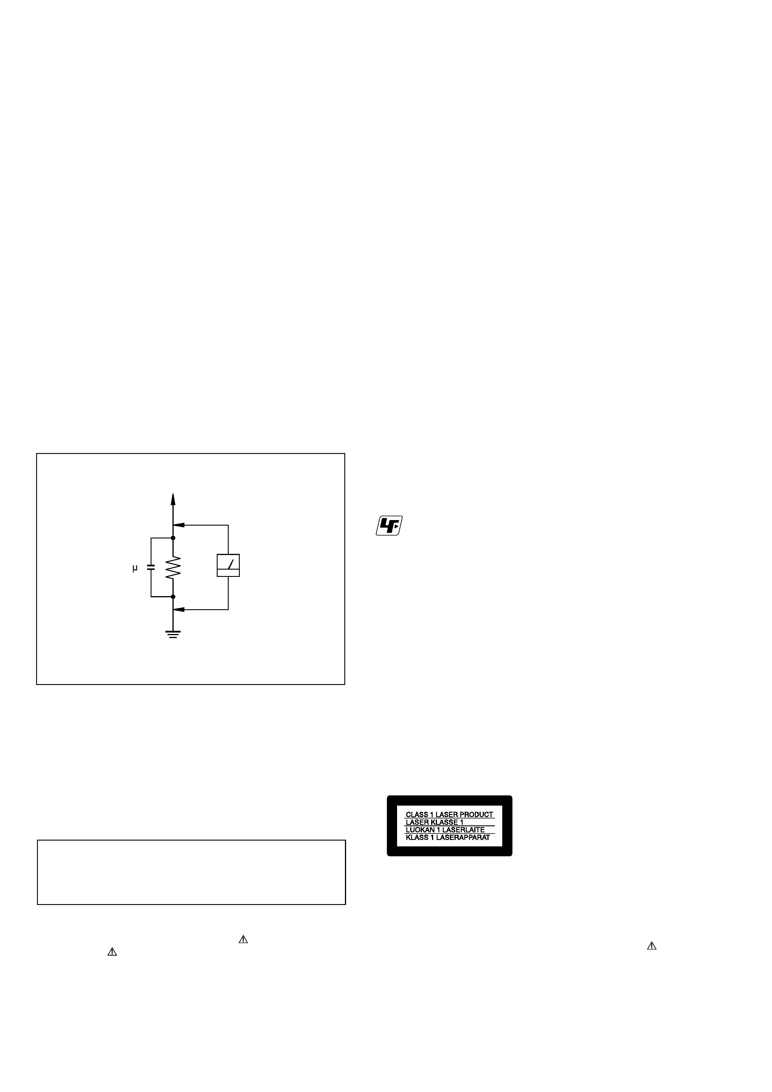
LEAKAGE TEST
The AC leakage from any exposed metal part to earth ground and
from all exposed metal parts to any exposed metal part having a
return to chassis, must not exceed 0.5mA (500 microampers).
Leakage current can be measured by any one of three methods.
1. A commercial leakage tester, such as the Simpson 229 or RCA
TW-540A. Follow the manufacturers' instructions to use these
instruments.
2. A battery-operated AC milliammeter. The Data Precision 245
digital multimeter is suitable for this job.
3. Measuring the voltage drop across a resistor by means of a
VOM or battery-operated AC volmeter. The "limit" indication
is 0.75V, so analog meters must have an accurate low voltage
scale. The Simpson 250 and Sanwa SH-63Trd are examples of
a passive VOM that is suitable. Nearly all battery operated
digital multimeters that have a 2V AC range are suitable. (See
Fig. A)
Unleaded solder
Boards requiring use of unleaded solder are printed with the lead-
free mark (LF) indicating the solder contains no lead.
(Caution: Some printed circuit boards may not come printed with
the lead free mark due to their particular size.)
: LEAD FREE MARK
Unleaded solder has the following characteristics.
· Unleaded solder melts at a temperature about 40°C highter than
ordinary solder.
Ordinary soldering irons can be used but the iron tip has to be
applied to the solder joint for a slightly longer time.
Soldering irons using a temperature regulator should be set to
about 350°C
Caution: The printed pattern (copper foil) may peel away if the
heated tip is applied for too long, so be careful!
· Strong viscosity
Unleaded solder is more viscous (sticky, less prone to flow) than
ordinary solder so use caution not to let solder bridges occur such
as on IC pins, etc.
· Usable with ordinary solder
It is best to use only unleaded solder but unleaded solder may also
be added to ordinary solder.
ATTENTION AU COMPOSANT AYANT RAPPORT
À LA SÉCURITÉ!
LES COMPOSANTS IDENTIFÉS PAR UNE MARQUE
SUR
LES DIAGRAMMES SCHÉMATIQUES ET LA LISTE DES PIÈCES
SONT
CRITIQUES
POUR
LA
SÉCURITÉ
DE
FONCTIONNEMENT. NE REMPLACER CES COMPOSANTS
QUE PAR DES PIÈSES SONY DONT LES NUMÉROS SONT
DONNÉS DANS CE MANUEL OU DANS LES SUPPÉMENTS
PUBLIÉS PAR SONY.
To Exposed Metal
Parts on Set
0.15 F
1.5k
AC
Voltmeter
(0.75 V)
Earth Ground
Fig.A. Using an Acvoltmeter to check AC leakage.

3
DVP-NS50P/NS41P/NS52P
TABLE OF CONTENTS
SERVICE NOTE
1.
Disc Removal Procedure (at POWER OFF) .............. 4
1.
GENERAL
Precautions .................................................................... 1-1
This Player Can Play the Following Discs ................... 1-1
Index to Parts and Controls ......................................... 1-1
Guide to the Control Menu Display .............................. 1-2
Hookups ................................................................................ 1-3
Hooking Up the Player .................................................. 1-3
Step 1: Unpacking ......................................................... 1-3
Step 2: Inserting Batteries into the Remote ................. 1-3
Step 3: Connecting the Video Cords ............................ 1-3
Step 4: Connecting the Audio Cords ............................ 1-4
Step 5: Connecting the Power Cord ............................. 1-4
Step 6: Quick Setup ...................................................... 1-4
Playing Discs ......................................................................... 1-5
Playing Discs ................................................................. 1-5
Resuming Playback from the Point Where You
Stopped the Disc (Multi-disc Resume) .................. 1-5
Using the DVD's Menu .................................................. 1-6
Selecting "ORIGINAL" or "PLAY LIST" on a
DVD-RW ................................................................... 1-6
Playing VIDEO CD's With PBC Functions
(PBC Playback) ........................................................ 1-6
Various Play Mode Functions (Programme Play,
Shuffle Play, Repeat Play, A-B Repeat Play ........... 1-6
Searching for a Scene .......................................................... 1-7
Searching for a Particular Point on a Disc (Search,
Scan, Slow-motion Play, Freeze Frame) ............... 1-7
Searching for a Title/Chapter/Track/Scene, etc. ......... 1-8
Searching by Scene (PICTURE NAVIGATION) ......... 1-8
Viewing Information About the Disc ..................................... 1-8
Checking the Playing Time and Remaining Time ........ 1-8
Sound Adjustments ............................................................... 1-9
Changing the Sound ...................................................... 1-9
TV Virtual Surround Settings (TVS) ............................. 1-9
Enjoying Movies .................................................................... 1-10
Changing the Angles ..................................................... 1-10
Displaying the Subtitles ................................................. 1-10
Adjusting the Playback Picture
(CUSTOM PICTURE MODE) ................................. 1-10
Sharpening the Pictures (SHARPNESS) ..................... 1-11
Enjoying MP3 Audio and JPEG Images .............................. 1-11
About MP3 Audio Tracks and JPEG Image Files ....... 1-11
Playing MP3 Audio Tracks and JPEG Image Files ..... 1-11
Enjoying JPEG Images as a Slide Show ..................... 1-12
Using Various Additional Functions ...................................... 1-12
Locking Discs (CUSTOM PARENTAL CONTROL,
PARENTAL CONTROL) .......................................... 1-12
Controlling Your TV with the Supplied Remote ............. 1-13
Settings and Adjustments ..................................................... 1-13
Using the Setup Display ............................................... 1-13
Setting the Display or Sound Track Language
(LANGUAGE SETUP) ............................................. 1-14
Settings for the Display (SCREEN SETUP) ................ 1-14
Custom Settings (CUSTOM SETUP) .......................... 1-14
Settings for the Sound (AUDIO SETUP) ..................... 1-14
Additional Information ............................................................ 1-15
Troubleshooting ............................................................. 1-15
Self-diagnosis Function (When letters/
numbers appear in the display ................................ 1-16
Glossary ........................................................................ 1-16
Specifications ................................................................. 1-16
2.
DISASSEMBLY
2-1.
Upper Case ................................................................... 2-1
2-2.
Front Panel Assembly ................................................... 2-1
2-3.
Loading Assembly ......................................................... 2-2
2-4.
Optical Pick-Up
(Device, Optical KHM-310CAA/C2RP) .................. 2-3
2-5.
MV-045 and IF124 Boards ............................................ 2-4
2-6.
Switching Regulator ...................................................... 2-4
2-7.
Interval Views ................................................................. 2-5
2-8.
Circuit Boards Location ................................................. 2-6
3.
BLOCK DIAGRAMS
3-1.
Overall Block Diagram .................................................. 3-1
3-2.
Power Line Block Diagram ........................................... 3-3
3-3.
System Control/Signal Processor Block Diagram ...... 3-5
3-4.
RF/Servo Block Diagram .............................................. 3-7
3-5.
Audio Block Diagram ..................................................... 3-9
3-6.
Video Block Diagram ..................................................... 3-11
3-7.
Interface Control Block Diagram .................................. 3-13
4.
PRINTED WIRING BOARDS AND
SCHEMATIC DIAGRAMS
4-1.
Frame Schematic Diagram ........................................... 4-1
4-2.
Printed Wiring Boards and Schematic Diagrams ........ 4-3
Waveform ...................................................................... 4-4
·
MV-045 Printed Wiring Board .................................. 4-5
·
MV-045 (CPU, Servo-DSP, AVDEC)
Schematic Diagram ............................................ 4-7
·
MV-045 (Drive) Schematic Diagram ....................... 4-9
·
MV-045 (Video) Schematic Diagram ....................... 4-11
·
MV-045 (Audio) Schematic Diagram ....................... 4-13
·
MV-045 (Power) Schematic Diagram ...................... 4-15
·
IF-124 Printed Wiring Board .................................... 4-17
·
IF-124 (Interface) Schematic Diagram .................. 4-19
·
Power Block (SRV1487UC) Printed Wiring Board . 4-21
·
Power Block (SRV1487UC) Schematic Diagram ... 4-23
·
Power Block (SRV1501WW) Printed Wiring Board 4-25
·
Power Block (SRV1501WW) Schematic Diagram . 4-27
5.
IC PIN FUNCTION DESCRIPTION
5-1.
System Control-Video Pin Function
(MV-045 BOARD IC101) .............................................. 5-1
6.
TEST MODE
6-1.
Executing IOP Measurement ....................................... 6-1
6-2.
Emergency History Check ........................................... 6-1
6-3.
Initializing Setup Data .................................................... 6-2
6-4.
Version Information ....................................................... 6-3
6-5.
If Con Self Diagnostic Function .................................... 6-3
7.
ELECTRICAL ADJUSTMENT
7-1.
Power Supply Output Voltage Check ........................... 7-1
7-2.
Adjustment of Video System ......................................... 7-2
8.
REPAIR PARTS LIST
8-1.
Exploded Views ............................................................. 8-1
8-1-1. Main Section ............................................................. 8-1
8-1-2. Mechanism Deck Assembly .................................... 8-3
8-2.
Electrical Parts List ....................................................... 8-4
4
DVP-NS50P/NS41P/NS52P
4E
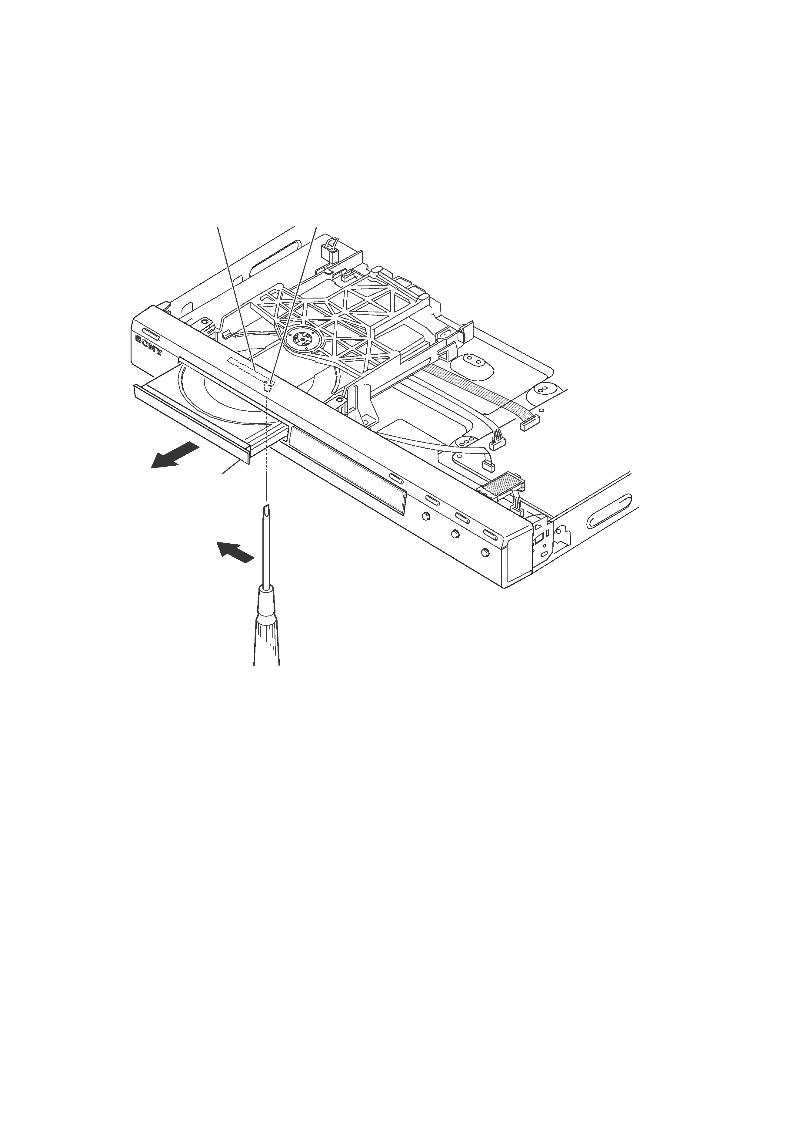
SERVICE NOTE
1. DISC REMOVAL PROCEDURE (at POWER OFF)
1) Open dust cover to access to a hole insert a tapering driver into the aperture of the unit bottom, and move the lever of chuck can in the
direction of the arrow A. (See Fig. 1)
2) Draw out the tray in the direction of the arrow B, and remove a disc. (See Fig. 1)
The lever of a zipper cam
Hold
B
Tray
A
Fig. 1.
1-1
DVP-NS50P/NS41P/NS52P
2
WARNING
To reduce the risk of fire or
electric shock, do not expose
this apparatus to rain or
moisture.
To avoid electrical shock, do
not open the cabinet. Refer
servicing to qualified
personnel only.
The AC power cord must be
changed only at a qualified
service shop.
CAUTION
The use of optical instruments with
this product will increase eye
hazard. As the laser beam used in
this CD/DVD player is harmful to
eyes, do not attempt to disassemble
the cabinet.
Refer servicing to qualified
personnel only.
This symbol is
intended to alert the
user to the presence
of uninsulated
"dangerous voltage"
within the product's enclosure that
may be of sufficient magnitude to
constitute a risk of electric shock to
persons.
This symbol is
intended to alert the
user to the presence
of important
operating and
maintenance (servicing)
instructions in the literature
accompanying the appliance.
CAUTION
You are cautioned that any
changes or modifications not
expressly approved in this manual
could void your authority to
operate this equipment.
Note
This equipment has been tested
and found to comply with the
limits for a Class B digital device,
pursuant to Part 15 of the FCC
Rules. These limits are designed to
provide reasonable protection
against harmful interference in a
residential installation. This
equipment generates, uses, and can
radiate radio frequency energy
and, if not installed and used in
accordance with the instructions,
may cause harmful interference to
radio communications. However,
there is no guarantee that
interference will not occur in a
particular installation. If this
equipment does cause harmful
interference to radio or television
reception, which can be
determined by turning the
equipment off and on, the user is
encouraged to try to correct the
interference by one or more of the
following measures:
Reorient or relocate the
receiving antenna.
Increase the separation
between the equipment and
receiver.
Connect the equipment into an
outlet on a circuit different
from that to which the receiver
is connected.
Consult the dealer or an
experienced radio/TV
technician for help.
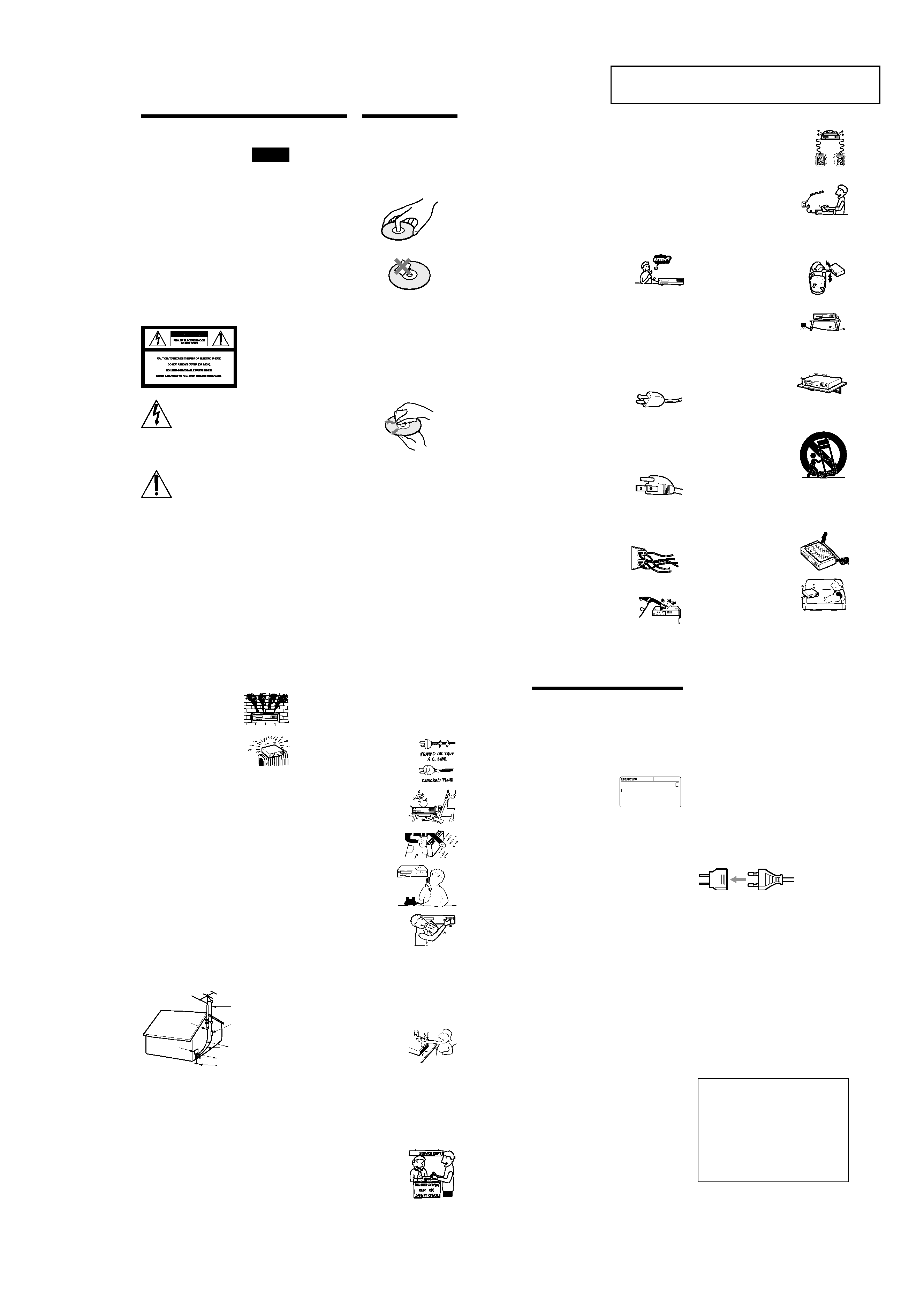
Notes About the
Discs
· To keep the disc clean, handle
the disc by its edge. Do not touch
the surface.
· Do not expose the disc to direct
sunlight or heat sources such as
hot air ducts, or leave it in a car
parked in direct sunlight as the
temperature may rise
considerably inside the car.
· After playing, store the disc in its
case.
· Clean the disc with a cleaning
cloth.
Wipe the disc from the center
out.
· Do not use solvents such as
benzine, thinner, commercially
available disc/lens cleaners, or
anti-static spray intended for
vinyl LPs.
· If you have printed the disc's
label, dry the label before
playing.
4
Antennas
Service
· Never place the set in a
confined space, such as a
bookcase, or built-in
cabinet, unless proper
ventilation is provided.
· Do not place the set near or
over a radiator or heat
register, or where it is
exposed to direct sunlight.
Outdoor antenna grounding
If an outdoor antenna or cable system is installed,
follow the precautions below.
An outdoor antenna system should not be located in the
vicinity of overhead power lines or other electric light
or power circuits, or where it can come in contact with
such power lines or circuits.
WHEN INSTALLING AN OUTDOOR ANTENNA
SYSTEM, EXTREME CARE SHOULD BE TAKEN
TO KEEP FROM CONTACTING SUCH POWER
LINES OR CIRCUITS AS CONTACT WITH THEM
IS ALMOST INVARIABLY FATAL.
Be sure the antenna system is grounded so as to provide
some protection against voltage surges and built-up static
charges. Section 810 of the National Electrical Code
provides information with respect to proper grounding of
the mast and supporting structure, grounding of the lead-in
wire to an antenna discharge unit, size of grounding
conductors, location of antenna-discharge unit, connection
to grounding electrodes, and requirements for the
grounding electrode.
Antenna Grounding According to the
National Electrical Code
Lightning
For added protection for this set during a lightning
storm, or when it is left unattended and unused for long
periods of time, unplug it from the wall outlet and
disconnect the antenna or cable system. This will
prevent damage to the set due to lightning and power-
line surges.
Antenna Lead in Wire
Ground Clamp
Antenna Discharge unit
(NEC Section 810-20)
Grounding Conductors
(NEC Section 810-21)
Ground Clamps
Power Service Grounding
Electrode System
(NEC Art 250 Part H)
Electric Service
Equipment
NEC-NATIONAL ELECTRICAL CODE
Damage Requiring Service
Unplug the set from the wall outlet and refer servicing
to qualified service personnel under the following
conditions:
· When the power cord or plug is
damaged or frayed.
· If liquid has been spilled or
objects have fallen into the
set.
· If the set has been exposed
to rain or water.
· If the set has been
subject to excessive
shock by being
dropped, or the cabinet
has been damaged.
· If the set does not operate
normally when following
the operating instructions.
Adjust only those controls
that are specified in the
operating instructions. Improper adjustment
of other controls may result in damage and
will often require extensive work by a
qualified technician to restore the set to normal
operation.
· When the set exhibits a distinct change in
performance - this indicates a need for service.
Servicing
Do not attempt to service the set
yourself as opening or removing
covers may expose you to
dangerous voltage or other
hazards.
Refer all servicing to qualified service personnel.
Replacement parts
When replacement parts are required, be sure the
service technician has used replacement parts specified
by the manufacturer that have the same characteristics
as the original parts.
Unauthorized substitutions may result in fire, electric
shock, or other hazards.
Safety Check
Upon completion of any service or
repairs to the set, ask the service
technician to perform routine
safety checks (as specified by the
manufacturer) to determine that
the set is in safe operating
condition.
5
Precautions
The power requirements and power
consumption of this player are indicated on
the back of the player. Check that the player's
operating voltage is identical with your local
power supply.
On safety
· To prevent fire or shock hazard, do not
place objects filled with liquids, such as
vases, on the apparatus.
· Should any solid object or liquid fall into
the cabinet, unplug the player and have it
checked by qualified personnel before
operating it any further.
On power sources
· The player is not disconnected from the AC
power source as long as it is connected to
the wall outlet, even if the player itself has
been turned off.
· If you are not going to use the player for a
long time, be sure to disconnect the player
from the wall outlet. To disconnect the AC
power cord, grasp the plug itself; never pull
the cord.
On placement
· Place the player in a location with adequate
ventilation to prevent heat build-up in the
player.
· Do not place the player on a soft surface
such as a rug.
· Do not place the player in a location near
heat sources, or in a place subject to direct
sunlight, excessive dust, or mechanical
shock.
· Do not install the player in an inclined
position. It is designed to be operated in a
horizontal position only.
· Keep the player and the discs away from
equipment with strong magnets, such as
microwave ovens, or large loudspeakers.
· Do not place heavy objects on the player.
On operation
· If the player is brought directly from a cold
to a warm location, or is placed in a very
damp room, moisture may condense on the
lenses inside the player. Should this occur,
the player may not operate properly. In this
case, remove the disc and leave the player
turned on for about half an hour until the
moisture evaporates.
· When you move the player, take out any
discs. If you don't, the disc may be
damaged.
For the model supplied with the AC plug
adaptor
If the AC plug of your unit does not fit into
the wall outlet, attach the supplied AC plug
adaptor.
On adjusting volume
Do not turn up the volume while listening to
a section with very low level inputs or no
audio signals. If you do, the speakers may be
damaged when a peak level section is played.
On cleaning
Clean the cabinet, panel, and controls with a
soft cloth slightly moistened with a mild
detergent solution. Do not use any type of
abrasive pad, scouring powder or solvent
such as alcohol or benzine.
On cleaning discs, disc/lens cleaners
Do not use a commercially available
cleaning disc or disc/lens cleaner (wet or
spray type). These may cause the
apparatus to malfunction.
If you have any questions or problems
concerning your player, please consult your
nearest Sony dealer.
DVPXXXX
00V 00Hz
00W
NO.
0-000-000-00
X
Power requirements and
power consumption
t
IMPORTANT NOTICE
Caution: This player is capable of holding a
still video image or on-screen display image
on your television screen indefinitely. If
you leave the still video image or on-screen
display image displayed on your TV for an
extended period of time you risk permanent
damage to your television screen. Plasma
display panel televisions and projection
televisions are susceptible to this.
3
Important
Safeguards
For your protection, please read these safety
instructions completely before operating the appliance,
and keep this manual for future reference.
Carefully observe all warnings, precautions and
instructions on the appliance, or the one described in
the operating instructions and adhere to them.
Use
Installation
Power sources
This set should be operated only
from the type of power source
indicated on the marking label. If
you are not sure of the type of
electrical power supplied to your
home, consult your dealer or local power company.
For those sets designed to operate from battery power,
or other sources, refer to the operating instructions.
Grounding or Polarization
This set is equipped with a polarized ac power cord
plug (a plug having one blade wider than the other), or
with a three-wire grounding type plug (a plug having a
third pin for grounding). Follow the instructions
below:
For the set with a polarized AC power
cord plug:
This plug will fit into the power
outlet only one way. This is a
safety feature. If you are unable to
insert the plug fully into the outlet, try reversing the
plug. If the plug should still fail to fit, contact your
electrician to have a suitable outlet installed. Do not
defeat the safety purpose of the polarized plug by
forcing it in.
For the set with a three-wire grounding
type AC plug:
This plug will only fit into a
grounding-type power outlet. This
is a safety feature. If you are
unable to insert the plug into the
outlet, contact your electrician to have a suitable outlet
installed. Do not defeat the safety purpose of the
grounding plug.
Overloading
Do not overload wall outlets,
extension cords or convenience
receptacles beyond their capacity,
since this can result in fire or
electric shock.
Object and Liquid Entry
Never push objects of any kind into
the set through openings as they
may touch dangerous voltage points
or short out parts that could result in
a fire or electric shock. Never spill
liquid of any kind on the set.
Attachments
Do not use attachments not
recommended by the manufacturer, as
they may cause hazards.
Cleaning
Unplug the set from the wall outlet
before cleaning or polishing it. Do
not use liquid cleaners or aerosol
cleaners. Use a cloth lightly
dampened with water for cleaning
the exterior of the set.
Water and Moisture
Do not use power-line operated sets
near water - for example, near a
bathtub, washbowl, kitchen sink, or
laundry tub, in a wet basement, or
near a swimming pool, etc.
Power-Cord Protection
Route the power cord so that it is
not likely to be walked on or
pinched by items placed upon or
against them, paying particular
attention to the plugs, receptacles, and the point where
the cord exits from the appliance.
Accessories
Do not place the set on an
unstable cart, stand, tripod,
bracket, or table. The set may
fall, causing serious injury to a
child or an adult, and serious damage to the set. Use
only a cart stand tripod, bracket, or table recommended
by the manufacturer.
An appliance and cart combination
should be moved with care. Quick
stops, excessive force, and uneven
surfaces may cause the appliance
and cart combination to overturn.
Ventilation
The slots and openings in the cabinet are provided for
necessary ventilation. To ensure reliable operation of
the set, and to protect it from overheating, these slots
and openings must never be blocked or covered.
· Never cover the slots and
openings with a cloth or
other materials.
· Never block the slots and
openings by placing the set
on a bed, sofa, rug or other
similar surface.
S3125A
,continued
SECTION 1
GENERAL
This section is extracted from instruction
manual. 2-581-693-13