MICROFILM
SERVICE MANUAL
Chinese Model
Hong Kong Model
Singapore Model
Taiwan Model
CD/DVD PLAYER
DVP-K330
RMT-D108E
SPECIFICATIONS
Continued on next page
2
WARNING!!
WHEN SERVICING, DO NOT APPROACH THE LASER
EXIT WITH THE EYE TOO CLOSELY. IN CASE IT IS
NECESSARY TO CONFIRM LASER BEAM EMISSION,
BE SURE TO OBSERVE FROM A DISTANCE OF
MORE THAN 25 cm FROM THE SURFACE OF THE
OBJECTIVE LENS ON THE OPTICAL PICK-UP BLOCK.
CAUTION:
The use of optical instrument with this product will increase eye
hazard.
SAFETY-RELATED COMPONENT WARNING!!
COMPONENTS IDENTIFIED BY MARK
! OR DOTTED
LINE WITH MARK
! ON THE SCHEMATIC DIAGRAMS
AND IN THE PARTS LIST ARE CRITICAL TO SAFE
OPERATION. REPLACE THESE COMPONENTS WITH
SONY PARTS WHOSE PART NUMBERS APPEAR AS
SHOWN IN THIS MANUAL OR IN SUPPLEMENTS PUB-
LISHED BY SONY.
CAUTION
Use of controls or adjustments or performance of procedures
other than those specified herein may result in hazardous ra-
diation exposure.
SAFETY CHECK-OUT
1. Check the area of your repair for unsoldered or poorly-sol-
dered connections. Check the entire board surface for solder
splashes and bridges.
2. Check the interboard wiring to ensure that no wires are
"pinched" or contact high-wattage resistors.
3. Look for unauthorized replacement parts, particularly transis-
tors, that were installed during a previous repair. Point them
out to the customer and recommend their replacement.
After correcting the original service problem, perform the following
safety checks before releasing the set to the customer:
4. Look for parts which, though functioning, show obvious signs
of deterioration. Point them out to the customer and recom-
mend their replacement.
5. Check the B+ voltage to see it is at the values specified.

3
Service Note ............................................................................ 4
1.
GENERAL
Getting Started ........................................................................ 1-1
Playing Discs ........................................................................... 1-3
Using Various Functions with the Control Menu ..................... 1-5
Enjoying Karaoke .................................................................... 1-10
Settings and Adjustments ........................................................ 1-11
Self-Diagnosis Function .......................................................... 1-14
Index to Parts and Controls ..................................................... 1-15
2.
DISASSEMBLY
2-1.
Case Removal ............................................................... 2-1
2-2.
MB-82 Board Removal .................................................. 2-1
2-3.
Power Block Removal ................................................... 2-1
2-4.
AU-214 Board Removal ................................................ 2-1
2-5.
Tray Cover Removal ..................................................... 2-2
2-6.
Front Panel Removal .................................................... 2-2
2-7.
Mechanism Deck Removal ........................................... 2-2
2-8.
Tray Removal ................................................................ 2-2
2-9.
Optical Pick-up Removal ............................................... 2-3
2-10. Belt, Loading Motor (M001),
MS-29/46, TK-51 Board Removal ................................. 2-3
2-11. Internal Views ................................................................ 2-4
2-12. Circuit Boards Location ................................................. 2-5
3.
BLOCK DIAGRAMS
3-1.
Overall Block Diagram .................................................. 3-1
3-2.
RF/Servo Block Diagram .............................................. 3-3
3-3.
Signal Process/Video Block Diagram ........................... 3-5
3-4.
System Control Block Diagram ..................................... 3-7
3-5.
Audio Block Diagram ..................................................... 3-9
3-6.
Interface Control Block Diagram ................................... 3-11
3-7.
Power Block Diagram .................................................... 3-13
4.
PRINTED WIRING BOARDS AND
SCHEMATIC DIAGRAMS
4-1.
Frame Schematic Diagram ........................................... 4-3
Frame (1) Schematic Diagram ...................................... 4-3
Frame (2) Schematic Diagram ...................................... 4-5
4-2.
Printed Wiring Boards and Schematic Diagrams ......... 4-7
TK-51 Printed Wiring Board .......................................... 4-7
TK-51 Schematic Diagram ............................................ 4-11
MS-29/46 Printed Wiring Board and
Schematic Diagram ....................................................... 4-13
MB-82 Printed Wiring Board ......................................... 4-15
MB-82 (AV DECODER) Schematic Diagram ................ 4-19
MB-82 (SDRAM) Schematic Diagram .......................... 4-21
MB-82 (SERVO DSP) Schematic Diagram .................. 4-23
MB-82 (DRIVE) Schematic Diagram ............................ 4-25
MB-82 (ARP) Schematic Diagram ................................ 4-27
MB-82 (SYSTEM CONTROL) Schematic Diagram ...... 4-29
MB-82 (HGA) Schematic Diagram ................................ 4-31
MB-82 (CLOCK GENERATOR)
Schematic Diagram ....................................................... 4-33
MB-82 (KARAOKE DSP) Schematic Diagram ............. 4-35
MB-82 (DAC) Schematic Diagram ................................ 4-37
MB-82 (BIAS) Schematic Diagram ............................... 4-39
AU-214 Printed Wiring Board ....................................... 4-41
AU-214 Schematic Diagram ......................................... 4-43
FL-103 Printed Wiring Board ........................................ 4-45
FL-103 (FUNCTION SWITCH)
Schematic Diagram ....................................................... 4-47
FL-103 (IF CON) Schematic Diagram .......................... 4-49
FR-153 Printed Wiring Board ........................................ 4-52
FR-153 Schematic Diagram .......................................... 4-53
MC-121 Schematic Diagram ......................................... 4-55
MC-121 Printed Wiring Board ....................................... 4-57
VR-71 Printed Wiring Board .......................................... 4-58
VR-71 Schematic Diagram ........................................... 4-59
HS-030SH/030SU Printed Wiring Board ...................... 4-61
HS-030SH/030SU Schematic Diagram ........................ 4-63
5.
IC PIN FUNCTION DESCRIPTION
5-1.
System Control Pin Function
(MB-82 Board IC202) .................................................... 5-1
6.
TEST MODE
6-1.
General Description ...................................................... 6-1
6-2.
Starting Test Mode ........................................................ 6-1
6-3.
Syscon Diagnosis .......................................................... 6-1
6-4.
Drive Auto Adjustment ................................................... 6-5
6-5.
Drive Manual Operation ................................................ 6-7
6-6.
Mecha Aging .................................................................. 6-9
6-7.
Emergency History ........................................................ 6-9
6-8.
Version Information ....................................................... 6-10
6-9.
Video Level Adjustment ................................................. 6-10
7.
ELECTRICAL ADJUSTMENTS
7-1.
Power Supply Adjustment ............................................. 7-1
1.
Power Supply Check (HS-030SH/030SU BOARD) ...... 7-1
7-2.
Adjustment of Video System ......................................... 7-2
1.
Video Level Adjustment (MB-82 BOARD) .................... 7-2
2.
S-terminal Output Check (MB-82 BOARD) .................. 7-2
3.
Checking Component Video Output B-Y
(MB-82 BOARD) ............................................................ 7-2
4.
Checking Component Video Output R-Y
(MB-82 BOARD) ............................................................ 7-2
5.
Checking Component Video Output Y
(MB-82 BOARD) ............................................................ 7-3
6.
Checking S Video Output S-C (MB-82 BOARD) .......... 7-3
7-3.
Adjustment Related Parts Arrangement ....................... 7-4
8.
REPAIR PARTS LIST
8-1.
Exploded Views ............................................................. 8-1
8-1-1. Case Assembly ......................................................... 8-1
8-1-2. Front Panel Assembly .............................................. 8-2
8-1-3. Chassis Assembly .................................................... 8-3
8-1-4. Mechanism Deck Assembly ..................................... 8-4
8-2.
Electrical Parts List ........................................................ 8-5
TABLE OF CONTENTS
Section
Title
Page
Section
Title
Page
4
SERVICE NOTE
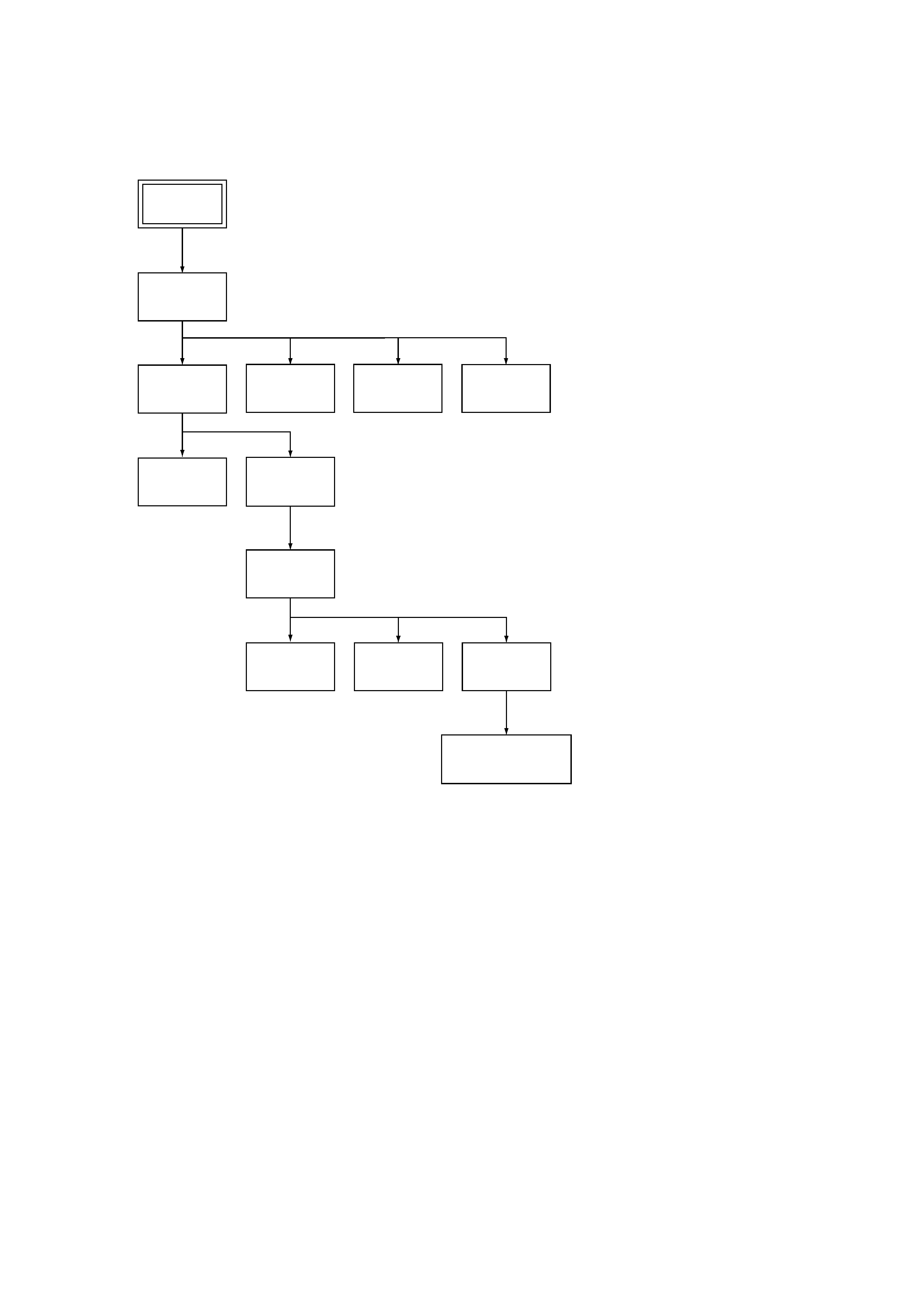
Set
Case
(Page 2-1)
Power
Block
(Page 2-1)
AU-214 Board
(Page 2-1)
Mechanism
Deck
(Page 2-2)
Front Panel
(Page 2-2)
Tray Cover
(Page 2-2)
Optical Pick-up
(Page 2-3)
TK-51 Board
(Page 2-3)
Belt
(Page 2-3)
Loading Motor (M001),
MS-29/46 Board
(Page 2-3)
Tray
(Page 2-2)
MB-82 Board
(Page 2-1)
1.
DISASSEMBLY
· This set can be disassembled in the order shown below.
5
4.
HOW TO SERVICE MB-82 BOARD
1) Remove the case from the set. (Refer to 2-1)
2) Remove the MB-82 board. (Refer to 2-1)
3) Set the MB-82 board as shown in Fig. 3.
Note: Do not disconnect wiring, except FMA-7/9/10.
Fig. 3
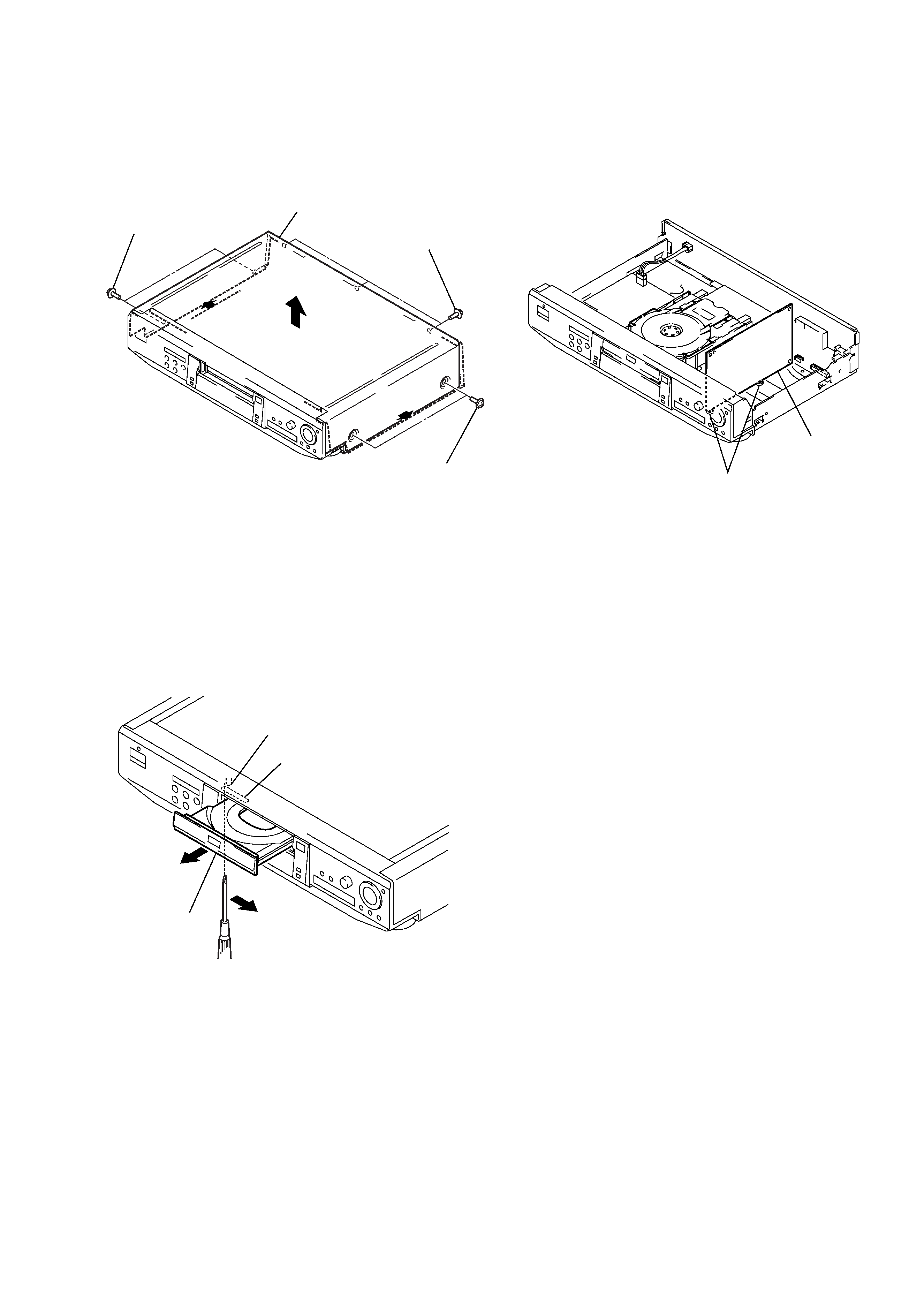
2.
NOTE ON REMOVE THE CASE
1) Remove seven screws. (See Fig. 1)
2) Open the side of case. (See Fig. 1)
3) Remove the case as lift straight. (See Fig. 1)
Fig. 1
3.
DISC REMOVAL PROCEDURE
(at POWER OFF)
1) Insert a tapering driver into the aperture of the unit bottom,
and move the lever of chuck cam in the direction of the arrow
A. (See Fig. 2)
2) Draw out the tray in the direction of the arrow B, and remove
a disc. (See Fig. 2)
Fig. 2
Two screws
Three screws
Case
Two screws
Lever of chuck cam
Aperture
Tray
A
B
MB-82 board
grooves