SERVICE MANUAL
US Model
PORTABLE CD/DVD PLAYER
DVP-FX1021
RMT-D163A
SPECIFICATIONS
DVD Player
Power supply:
DC 9.8V (AC adaptor/ Car Battery Charger terminal),
DC 7.6V (Battery)
Power consumption: 12W with battery (Charge)
Weight: 2.34 lbs (1.062kg) (without battery pack)
External dimensions (W x H x D):
10.2 x 1.1 x 7.5 inches (258 x 28.2 x 191.3 mm)
Signal system: NTSC
Laser:
DVD Laser wavelength 662+25 / 662-15 nm
CD Laser wavelength 785+25 / 785-15 nm
Frequency range (audio):
DVD linear sound: 48kHz sampling 8 Hz to 20 kHz
96kHz sampling 8 Hz to 44 kHz
Signal-to-noise ratio (audio): More than 95 dB
Dynamic range (audio): More than 95 dB
Harmonic distortion (audio): 0.008 %
Operating conditions:
Temperature: 41°F to 95°F, Operation status: Horizontal
Connectors
Video input/output (VIDEO In/Out):
1.0 V (p-p), 75
, negative sync., ø3.5mm mini jack x 1
Audio input/output (AUDIO In/Out, analog audio):
2.0 Vrms(1 KHz, 0 dB), ø3.5mm mini jack x 1
Earphone terminal: ø3.5mm stereo mini jack x 2
Liquid Crystal Display
Panel size: 10.2 inches wide (diagonal)
Projection system: R.G.B
Driving system: TFT active matrix
Resolution: 800 x 480
(effective pixel rate: more than 99.99%)
Supplied Accessories
· RCA Audio/Video cable . . . . . . . . . . . . . . . . . . . . . .1
·AC Adaptor (AC-FX101) . . . . . . . . . . . . . . . . . . . . . .1
·AC Power Cord . . . . . . . . . . . . . . . . . . . . . . . . . . . .1
· Car Battery Charger (DCC-FX101) . . . . . . . . . . . . . .1
· Battery Pack (NP-FX1021) . . . . . . . . . . . . . . . . . . . .1
· Remote control (RMT-D163A) . . . . . . . . . . . . . . . . .1
·Battery for Remote control (Size : AA(R6)) . . . . . . . .1
· Design and specifications are subject to change
without notice.
2
WARNING!!
WHEN SERVICING, DO NOT APPROACH THE LASER
EXIT WITH THE EYE TOO CLOSELY. IN CASE IT IS
NECESSARY TO CONFIRM LASER BEAM EMISSION,
BE SURE TO OBSERVE FROM A DISTANCE OF
MORE THAN 25 cm FROM THE SURFACE OF THE
OBJECTIVE LENS ON THE OPTICAL PICK-UP BLOCK.
CAUTION
Use of controls or adjustments or performance of procedures
other than those specified herein may result in hazardous ra-
diation exposure.
SAFETY-RELATED COMPONENT WARNING!!
COMPONENTS IDENTIFIED BY MARK 0 OR DOTTED
LINE WITH MARK 0 ON THE SCHEMATIC DIAGRAMS
AND IN THE PARTS LIST ARE CRITICAL TO SAFE
OPERATION. REPLACE THESE COMPONENTS WITH
SONY PARTS WHOSE PART NUMBERS APPEAR AS
SHOWN IN THIS MANUAL OR IN SUPPLEMENTS PUB-
LISHED BY SONY.
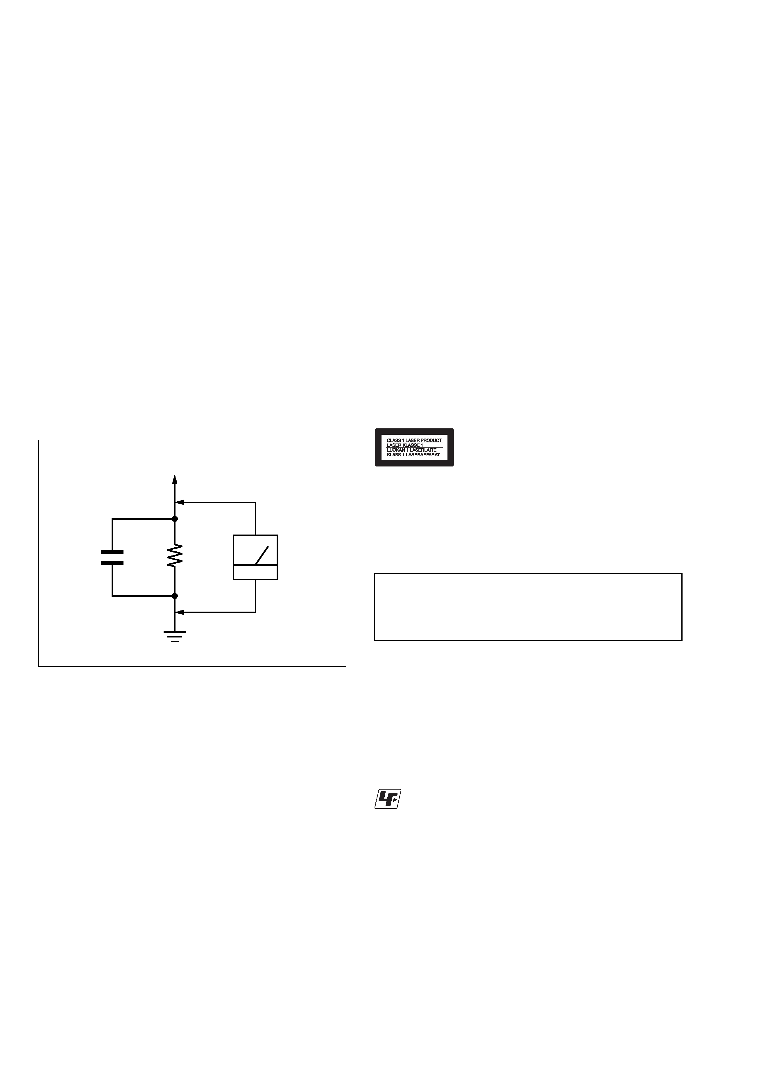
Fig. A.
Using an AC voltmeter to check AC leakage.
1.5 k
0.15
µF
AC
voltmeter
(0.75 V)
To Exposed Metal
Parts on Set
Earth Ground
LEAKAGE TEST
The AC leakage from any exposed metal part to earth ground
and from all exposed metal parts to any exposed metal part having
a return to chassis, must not exceed 0.5 mA (500 microamperes).
Leakage current can be measured by any one of three methods.
1. A commercial leakage tester, such as the Simpson 229 or RCA
WT-540A. Follow the manufacturers' instructions to use these
instruments.
2. A battery-operated AC milliammeter. The Data Precision 245
digital multimeter is suitable for this job.
3. Measuring the voltage drop across a resistor by means of a
VOM or battery-operated AC voltmeter. The "limit" indica-
tion is 0.75V, so analog meters must have an accurate low-
voltage scale. The Simpson 250 and Sanwa SH-63Trd are ex-
amples of a passive VOM that is suitable. Nearly all battery
operated digital multimeters that have a 2V AC range are suit-
able. (See Fig. A)
1. Check the area of your repair for unsoldered or poorly-sol-
dered connections. Check the entire board surface for solder
splashes and bridges.
2. Check the interboard wiring to ensure that no wires are
"pinched" or contact high-wattage resistors.
3. Look for unauthorized replacement parts, particularly transis-
tors, that were installed during a previous repair. Point them
out to the customer and recommend their replacement.
4. Look for parts which, though functioning, show obvious signs
of deterioration. Point them out to the customer and recom-
mend their replacement.
5. Check the line cord for cracks and abrasion. Recommend the
replacement of any such line cord to the customer.
6. Check the B+ voltage to see it is at the values specified.
7. Check the antenna terminals, metal trim, "metallized" knobs,
screws, and all other exposed metal parts for AC leakage.
Check leakage as described below.
SAFETY CHECK-OUT
After correcting the original service problem, perform the following
safety checks before releasing the set to the customer:
CAUTION:
The use of optical instrument with this product will increase eye
hazard.
This CD/DVD player is CLASS 1 LASER PRODUCT.
Unleaded solder
Boards requiring use of unleaded solder are printed with the lead-
free mark (LF) indicating the solder contains no lead.
(Caution: Some printed circuit boards may not come printed with
the lead free mark due to their particular size.)
: LEAD FREE MARK
Unleaded solder has the following characteristics.
· Unleaded solder melts at a temperature about 40
°C higher than
ordinary solder.
Ordinary soldering irons can be used but the iron tip has to be
applied to the solder joint for a slightly longer time.
Soldering irons using a temperature regulator should be set to
about 350
°C.
Caution: The printed pattern (copper foil) may peel away if the
heated tip is applied for too long, so be careful!
· Strong viscosity
Unleaded solder is more viscous (sticky, less prone to flow) than
ordinary solder so use caution not to let solder bridges occur
such as on IC pins, etc.
· Usable with ordinary solder
It is best to use only unleaded solder but unleaded solder may
also be added to ordinary solder.

3
TABLE OF CONTENTS
Section
Title
Page
Section
Title
Page
1.
GENERAL
Precautions ................................................................... 1-1
About This Manual ........................................................ 1-4
This Player Can Play the Following Discs .................... 1-4
Notes on playback operations of DVDs and VIDEO
CDs ................................................................................ 1-5
Copyrights ..................................................................... 1-5
Notes about the Discs ................................................... 1-5
Identification of Controls ............................................... 1-6
Power Connections ....................................................... 1-9
Playing a Disc ................................................................ 1-10
On-Screen Display ........................................................ 1-13
General Features .......................................................... 1-14
Playing an Audio CD or MP3 Disc ................................ 1-15
Programmed Playback .................................................. 1-17
Random Play ................................................................. 1-18
Viewing a JPEG Disc .................................................... 1-18
Initial Settings ................................................................ 1-19
Setting up the Player ..................................................... 1-22
To use the player with car battery charger ................... 1-23
Troubleshooting ............................................................. 1-25
Language Code List ...................................................... 1-25
Country Code List ......................................................... 1-26
2.
DISASSEMBLY
2-1.
Cabinet Assy Removal .................................................. 2-1
2-2.
CD Lid, MD, Main Board Removal ................................ 2-2
2-3.
LCD Panel Removal ...................................................... 2-3
3.
BLOCK DIAGRAMS
3-1.
Oveall Block Diagram .................................................... 3-1
3-2.
Power Block ................................................................... 3-3
3-3.
TFT-LCD Power/Battery Charge Block ......................... 3-5
3-4.
Front Micom Block ......................................................... 3-7
3-5.
Front End Block ............................................................. 3-9
3-6.
MAIN Mcu Block ............................................................ 3-11
3-7.
Video Block (1) .............................................................. 3-13
3-8.
Video Block (2) .............................................................. 3-15
3-9.
Audio Block .................................................................... 3-17
4.
SCHEMATIC DIAGRAMS
4-1.
Frame (1/2) .................................................................... 4-1
Frame (2/2) .................................................................... 4-3
4-2.
Main Power .................................................................... 4-5
4-3.
Servo ............................................................................. 4-7
4-4.
Audio .............................................................................. 4-9
4-5.
Video .............................................................................. 4-11
4-6.
Mpeg (MTK1389) .......................................................... 4-13
4-7.
Battery Charge .............................................................. 4-15
4-8.
Front Micom ................................................................... 4-17
4-9.
LCD Power .................................................................... 4-19
4-10. TFT-LCD Power ............................................................. 4-21
4-11. TFT-LCD UPS181 ......................................................... 4-23
4-12. TN-LCD ......................................................................... 4-25
4-13. KEY ................................................................................ 4-27
5.
PRINTED WIRING BOARDS
5-1.
Circuit Boards Location ................................................. 5-1
5-2.
MAIN Board ................................................................... 5-3
5-3.
TFT-LCD Board ............................................................. 5-7
5-4.
TN-LCD Board ............................................................... 5-9
5-5.
KEY Board ..................................................................... 5-11
6.
WAVEFORMS
6-1.
Details and Waveforms on System Test
and Debugging .............................................................. 6-1
7.
IC PIN FUNCTION DESCRIPTION
7-1.
MPEG/DSP/RF Pin Function
(MAIN Board IC500: MT1389) ...................................... 7-1
7-2.
FRONT MICOM Pin Function
(MAIN Board IC701: uPD78F9418AGK) ....................... 7-7
8.
ELECTRICAL ADJUSTMENT
8-1.
LCD Adjustment ............................................................ 8-1
1.
Power Measuring ........................................................... 8-1
2.
VCOM Waveform Adjustment ....................................... 8-1
3.
TFT Panel Check ........................................................... 8-1
8-2.
Standard Video Level .................................................... 8-2
1.
Checking Video Output Level ........................................ 8-2
2.
Checking S Video Output S-Y ....................................... 8-2
3.
Checking S Video Output S-C ....................................... 8-2
8-3.
Adjustment and Checking Location .............................. 8-3
9.
TROUBLESHOOTING
9-1.
Electrical Trouble Shooting Guide ................................. 9-1
1.
Power (DC-DC Converter) Circuit ................................. 9-1
2.
MPEG Circuit ................................................................. 9-4
3.
Front Circuit (Dogotrpm & Key) ..................................... 9-5
4.
RF/Servo Circuit ............................................................ 9-6
9-2.
LCD Trouble Shooting Guide (1/2) ................................ 9-10
9-3.
LCD Trouble Shooting Guide (2/2) ................................ 9-11
10.
REPAIR PARTS LIST
10-1. Exploded Views ............................................................. 10-1
10-1-1. LCD Panel Section ................................................... 10-1
10-1-2. Upper Case Section ................................................. 10-2
10-1-3. Bottom Case Section ............................................... 10-3
10-2. Electrical Parts List ....................................................... 10-4

4
MEMO
1-1
SECTION 1
GENERAL
This section is extracted from instruc-
tion manual (2-349-874-11).
DVP-FX1021
Precautions
4
Owner's Record
The model and serial numbers are located on the bottom of the unit. Record the serial number in the space provided
below. Refer to them whenever you call upon your Sony dealer regarding this product.
Model No. DVP-FX1021
Serial No.______________
CAUTION
You are cautioned that any changes or modifications not expressly approved in this manual could void your authority to
operate this equipment.
NOTE
This equipment has been tested and found to comply with the limits for a Class B digital device, pursuant to Part 15 of the
FCC Rules. These limits are designed to provide reasonable protection against harmful interference in a residential installa-
tion. This equipment generates, uses, and can radiate radio frequency energy and, if not installed and used in accordance
with the instructions, may cause harmful interference to radio communications. However, there is no guarantee that interfer-
ence will not occur in a particular installation. If this equipment does cause harmful interference to radio or television recep-
tion, which can be determined by turning the equipment off and on, the user is encouraged to try to correct the interference
by one or more of the following measures:
Reorient or relocate the receiving antenna.
Increase the separation between the equipment and receiver.
Connect the equipment into an outlet on a circuit different from that to which the receiver is connected.
Consult the dealer or an experienced radio/TV technician for help.
Introductions
5
Precautions (continued)
· The power requirements and power consumption of this
unit are indicated on the AC power adaptor. Check that
the unit's operating voltage is identical with your local
power supply.
On safety
· Caution The use of optical instruments with this product
will increase eye hazard.
· To prevent fire or shock hazard, do not place objects filled
with liquids, such as vases, on the apparatus.
· Should any solid object or liquid fall into the cabinet,
unplug the player and have it checked by qualified per-
sonnel before operating it any further.
· Do not put any foreign objects in the DC IN 9.8V (external
power input) jack.
On temperature increases
· Heat may build up while charging or during extented use.
This is not a malfunction.
· If the surrounding temperature is very high, the protective
function will turn off the player automatically.
Leave the player in a cool location for about 30 minutes
before using it again.
On power sources
· Use only the supplied AC power adaptor. Do not use any
other AC power adaptor. It may cause a malfunction.
· If the AC power adaptor causes interference to radio
reception, move it away from the radio.
· Do not touch the AC power adaptor with wet hands.
· Even when the player is turned off, it is still connected to
the AC power source (mains) as long as it remains
connected to the wall outlet.
· If you are not going to use the player for a long time, be
sure to disconnect the player from the wall outlet. To dis-
connect the AC power cord (mains lead), grasp the plug
itself; never pull the cord.
· Should the AC power cord need to be changed, have it
done at a qualified service shop only.
· Use a commercially available AC plug adaptor, if neces-
sary, depending on the design of the wall outlet.
Polarity of the plug
Wall outlet
AC plug adaptor
AC-FX101