DVMC-DA1
US Model
Canadian Model
SERVICE MANUAL
MEDIA CONVERTER
9-928-112-11
Power requirements
DC IN 6V jack accepts the AC-MZ60A AC power adapter
(supplied), AC 120 V, 60 Hz
Power consumption
AC 120 V, 60 Hz, 5.1 W (max., AC power adapter)
Operating temperature
10
°C to 35°C (50°F to 95°F)
Operating humidity
40 % to 80 %
Storage temperature
20
°C to 80°C (4°F to 176°F)
Storage humidity
20 % to 80 %
Dimensions (approx.)
124
× 44 × 90.5 mm (5 × 13/4 × 35/8 inches)
(w/h/d, excluding projections)
Mass (approx.)
300 g (10 oz) (unit only)
Input/output connector
S-VIDEO IN: Mini DIN 4-pin (1)
S-VIDEO OUT: Mini DIN 4-pin (1)
VIDEO IN: RCA pin (1)
VIDEO OUT: RCA pin (1)
AUDIO IN: RCA pin (2): L, R
AUDIO OUT: RCA pin (2): L, R
DV IN/OUT: S100 (100 Mbps) 4-pin (1)
Supplied accessories
Design and specifications are subject to change without
notice.
AC power adapter (AC-MZ60A)
DV connecting cable
Audio/video connecting cable
S-video connecting cable
Operating instructions
Owner registration card
Warranty card
Important safe guard
SPECIFICATIONS

-- 2 --
SAFETY-RELATED COMPONENT WARNING!!
COMPONENTS IDENTIFIED BY MARK
! OR DOTTED LINE WITH
MARK
! ON THE SCHEMATIC DIAGRAMS AND IN THE PARTS
LIST ARE CRITICAL TO SAFE OPERATION. REPLACE THESE
COMPONENTS WITH SONY PARTS WHOSE PART NUMBERS
APPEAR AS SHOWN IN THIS MANUAL OR IN SUPPLEMENTS
PUBLISHED BY SONY.
ATTENTION AU COMPOSANT AYANT RAPPORT
À LA SÉCURITÉ!
LES COMPOSANTS IDENTIFÉS PAR UNE MARQUE
! SUR LES
DIAGRAMMES SCHÉMATIQUES ET LA LISTE DES PIÈCES SONT
CRITIQUES POUR LA SÉCURITÉ DE FONCTIONNEMENT. NE
REMPLACER CES COMPOSANTS QUE PAR DES PIÈSES SONY
DONT LES NUMÉROS SONT DONNÉS DANS CE MANUEL OU
DANS LES SUPPÉMENTS PUBLIÉS PAR SONY.
1.
GENERAL ····························································· 1-1
2.
BLOCK DIAGRAMS
2-1.
OVERALL BLOCK DIAGRAM ···································· 2-1
2-2.
POWER BLOCK DIAGRAM ········································ 2-3
3.
PRINTED WIRING BOARDS AND SCHEMATIC
DIAGRAMS
· SWX-22 (SWITCH) SCHEMATIC DIAGRAM ·········3-2
· SWX-22 (SWITCH) PRINTED WIRING BOARD ····3-3
· IFX-52 (MAIN : SIDE A)
PRINTED WIRING BOARD ······································ 3-5
· IFX-52 (MAIN : SIDE B)
PRINTED WIRING BOARD ······································ 3-7
· IFX-52 (J CORE) SCHEMATIC DIAGRAM ··············3-9
· IFX-52 (VFD) SCHEMATIC DIAGRAM ················· 3-11
· IFX-52 (MECH CON) SCHEMATIC DIAGRAM ····3-13
· IFX-52 (HI) SCHEMATIC DIAGRAM ·····················3-15
· IFX-52 (DC CON) SCHEMATIC DIAGRAM ··········3-17
· IFX-52 (AMP) SCHEMATIC DIAGRAM ················3-19
· IFX-52 (AGC) SCHEMATIC DIAGRAM ················3-21
· IFX-52 (AUDIO) SCHEMATIC DIAGRAM ············3-23
· IFX-52 (JACK) SCHEMATIC DIAGRAM ···············3-25
· IFX-52 (CN) SCHEMATIC DIAGRAM ···················3-26
4.
ELECTRICAL ADJUSTMENT ·························· 4-1
5.
REPAIR PARTS LIST
5-1.
EXPLODED VIEWS ······················································ 5-1
5-2.
ELECTRICAL PARTS LIST ·········································· 5-2
TABLE OF CONTENTS
1-1
DVMC-DA1
SECTION 1
GENERAL
This section is extracted
from instruction manual
(3-864-717-11).
3
-US
Table
of
contents
Overview
1-2
Checking
the
supplied
parts
and
accessories
1-3
Duplicating
analog
video
to
digital
video
1-3
Connecting
an
analog
video
unit
and
a
DV
unit
via
the
media
converter
1-3
Duplicating
analog
video
to
digital
video
1-4
Duplicating
digital
video
to
analog
video
1-4
Viewing
digital
video
on
your
TV
1-5
Connecting
a
DV
unit
and
a
TV
via
the
media
converter
1-5
V
iewing
digital
video
on
your
TV
1-5
Playing
back
the
audio
while
changing
the
mixing
rate
1-5
Capturing
images
fr
om
an
analog
video
unit
using
a
PC
1-6
Connecting
a
PC
and
an
analog
video
unit
via
the
media
converter
1-6
Capturing
images
fr
om
an
analog
video
unit
using
a
PC
1-6
Recor
ding
analog
video
fr
om
a
PC
1-6
Pr
ecautions
1-7
Technical
information
1-8
Signal
flows
1-8
Output/input
of
analog
video
signals
1-8
Copyright
pr
ecautions
1-8
DV
r
ecor
ding
format
1-9
12-bit/16-bit
audio
modes
1-9
Locating
the
parts
and
contr
ols
1-1
23
-US
Locating
the
parts
and
contr
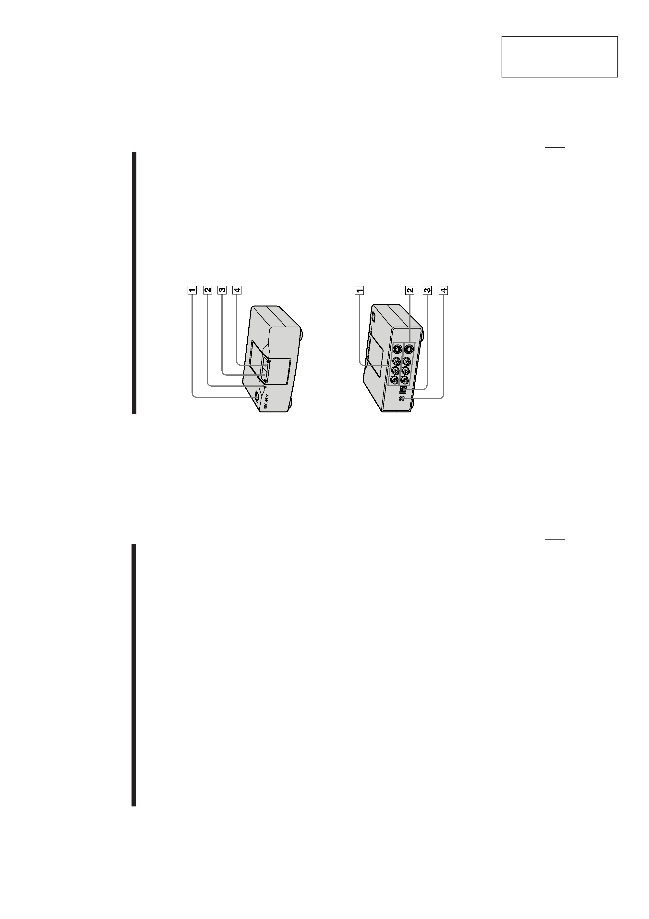
ols
Front
1
POWER
button
Turns
on/off
the
media
converter.
2
PROTECT
indicator
Lights
when
the
input
picture
includes
acopy
protection
signal.
You
cannot
record
the
signal
when
this
indicator
is
lit.
3
ANALOG
IN
key
and
indicator
Select
the
signal
input
from
the
AUDIO/VIDEO/S-VIDEO
IN
as
the
input
signal
to
the
media
converter.
4
DV
IN
key
and
indicator
Select
the
signal
input
from
the
DV
IN/
OUT
as
the
input
signal
to
the
media
converter.
Rear
1
AUDIO/VIDEO/S-VIDEO
IN
connectors
Connect
to
the
analog
video
unit.
When
you
connect
both
the
S-VIDEO
IN
and
VIDEO
IN
connectors,
the
S-
video
signal
is
automatically
selected.
When
connecting
to
VIDEO
IN
connectors
only,
no
signals
are
output
from
the
S-VIDEO
OUT
connector.
2
AUDIO/VIDEO/S-VIDEO
OUT
connectors
Connect
to
the
analog
video
unit
or
TV.
3
DV
IN/OUT
connector
Connect
to
the
DV
unit.
4
DC
IN
6V
connector
Connect
to
the
supplied
AC
power
adapter.
1-2
4
-US
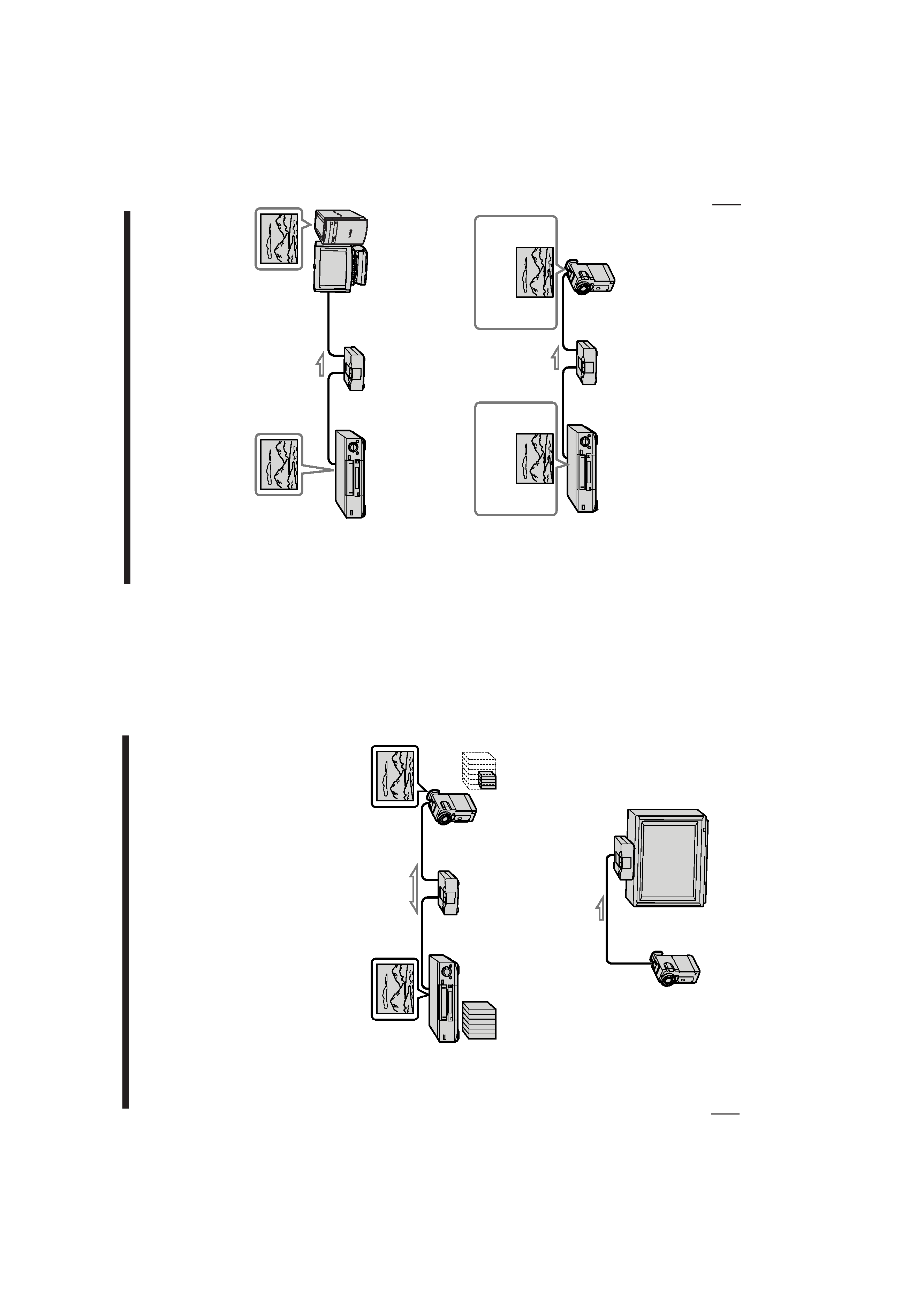
Overview
The
DVMC-DA1
is
a
media
converter
unit
which
converts
analog
video
signals
to
digital
video
signals
and
vice
versa.
Converting
pictures
and
sound
from
8
mm/VHS
format
to
DV
format
and
vice
versa
(pages
8
-
10)
You
can
convert
analog
video
on
Hi8,
8
mm,
or
VHS
format
cassettes
to
digital
video
(DV)
by
connecting
both
analog
and
digital
video
units
via
the
media
converter.
MPEG
data
cannot
be
converted
as
a
digital
signal.
Since
pictures
and
sound
are
recorded
on
the
DV
unit
in
digital
format,
little
or
no
picture
and
sound
quality
are
lost.
You
can
also
convert
digital
video
to
analog
video.
Note
You
cannot
record
video
which
includes
copyright
protection
signals.
Viewing
pictures
from
the
DV
unit
(page
11,
12)
You
can
enjoy
high
quality
digital
video
when
you
connect
a
DV
unit
to
aTV
via
the
media
converter
using
the
DV
connecting
cable.
In
this
case,
you
do
not
have
to
change
the
connection
between
your
TV
and
the
other
analog
video
unit.
Digital
Analog
8
mm/VHS
Digital
video
5
-US
Capturing
images
from
an
analog
video
unit
using
a
PC
(page
13,
14)
You
can
capture
images
from
an
analog
video
unit
connected
to
your
PC
via
the
media
converter
using
the
DV
(i.Link)
connector.
In
this
case,
you
can
edit
a
movie
or
add
titles
using
your
PC.
You
can
also
print
out
the
captured
images
using
your
PC
printer
instead
of
a
video
printer.
Selecting
the
audio
mode
when
recording
to
the
DV
unit
(page
9)
You
can
add
messages
or
background
music
after
recording.
When
you
record
to
the
DV
unit
from
an
analog
video
unit,
you
can
select
16-bit
audio
mode
for
higher
quality,
or
12-bit
audio
mode
for
adding
messages
or
background
music
(post
sound
recording).
Listening
to
the
audio
with
the
desired
mixing
rate
(page
12)
When
playing
back
video
recorded
in
12-bit
audio
mode
on
a
DV
unit
via
the
media
converter,
you
can
listen
to:
the
recorded
message
and/or
background
music
only
(post
sound
recording),
the
original
audio,
or
the
combined
audio
of
both
tracks
with
the
desired
mixing
rate
(5
steps).
Original
sound
Original
sound
+
Added
sound
1-3
6
-US
Checking
the
supplied
parts
and
accessories
Check
to
make
sure
you
have
received
the
following
items
in
the
carton.
If
something
is
missing,
contact
your
Sony
dealer
or
service
facility.
AC
power
adapter
(AC-MZ60A)
DV
connecting
cable
Audio/video
connecting
cable
S-video
connecting
cable
Operating
instructions
Owner
registration
card
Warranty
card
Important
safe
guard
8
-US
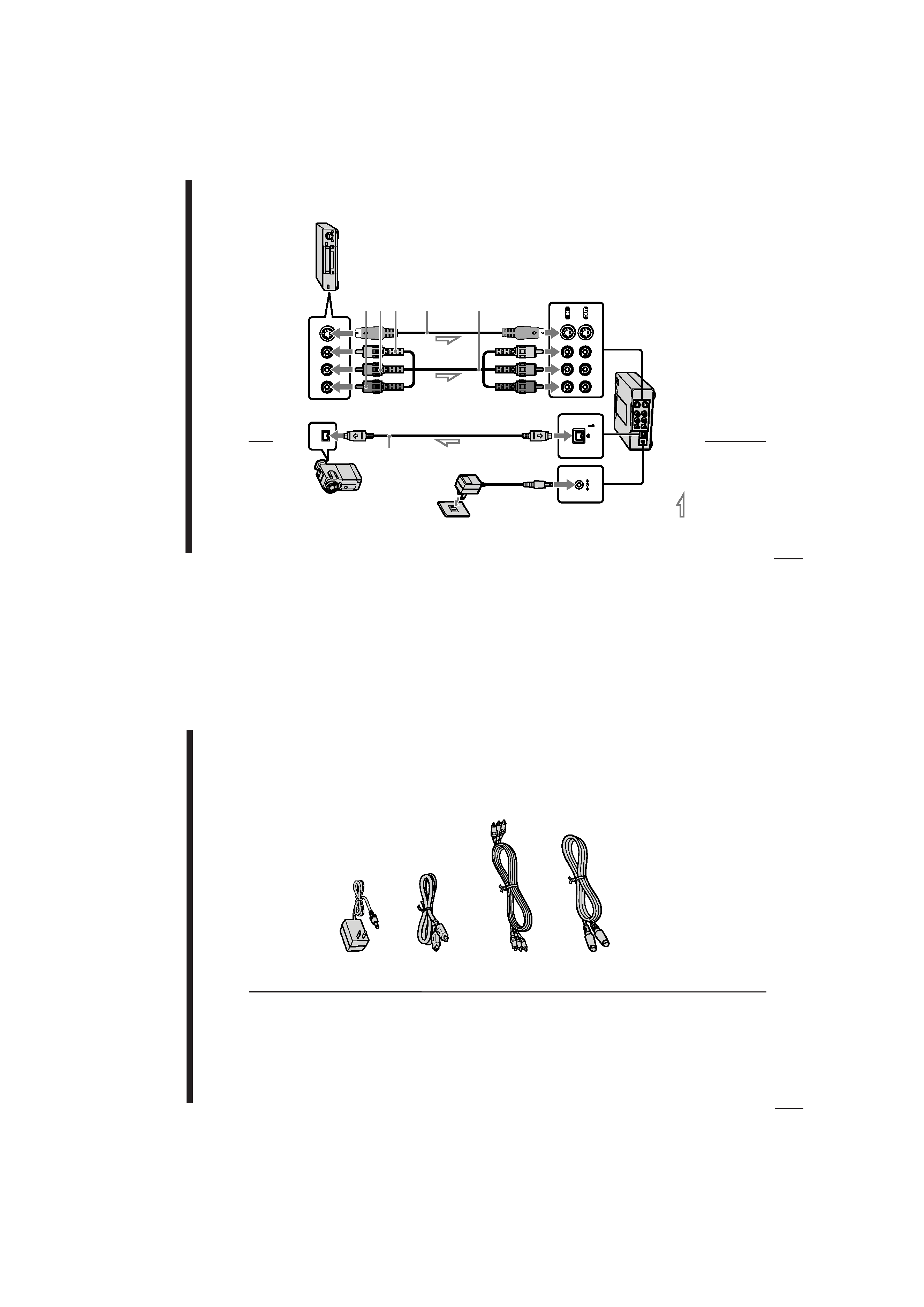
RL
AUDIO
V
IDEO
S-VIDEO
DV
DV
IN/OUT
DC
IN
6V
Connecting
an
analog
video
unit
and
a
DV
unit
via
the
media
converter
to
Audio/video
output
to
S-video
output
to
DV
input/output
Audio
L
(white)
Audio
R
(red)
Video
(yellow)
S-video
connecting
cable
(supplied)
Audio/video
connecting
cable
(supplied)
DV
connecting
cable
(supplied)
:Signal
flow
to
wall
outlet
AC
power
adapter
(supplied)
Duplicating
analog
video
to
digital
video