MICROFILM
PORTABLE VIDEO CD PLAYER
E Model
Chinese Model
Tourist Model
Model Name Using Similar Mechanism
D-223
CD Mechanism Type
KSM-331CAN (S)
Optical Pick-Up Name
KSS-331C
System
Compact disc digital audio/video system
Laser diode properties
Material: GaAlAs
Wavelength:
=780 nm
Emission duration: Continuous
Laser output power: Less than 44.6 µW*
* This output is the value measured at a distance of 200 mm from
the objective lens surface on the optical pick-up block with 7 mm
aperture.
Error correction
Sony Super Strategy Cross Interleave Reed Solomon Code
D-A conversion
1-bit
Channel number
2 channels
Frequency response
20 - 20,000 Hz
dB (measured by EIAJ CP-307)
Output (at 6 V input level)
Headphones (stereo minijack)
10 mW + 10 mW at 16 ohms
Line output (stereo minijack)
Output level 0.7 V rms at 47 kilohms
Recommended load impedance over 10 kilohms
Video output (minijack)
Output level 1 Vp-p at 75 ohms
Recommended load impedance over 75 ohms
General
Power requirements
Player:
· Four LR6 (size AA) batteries: 6 V DC
· AC power adaptor (DC IN 6 V jack):
120 V, 60 Hz
220 - 230 V, 50/60 Hz
100 - 240 V, 50/60 Hz
(AC power required differs depending on where you purchased
the player.)
Remote control:
· Two LR6 (size AA) batteries 3 V DC
Dimensions (w/h/d) (incl. projecting parts and controls)
Approx. 140.5
× 30.5 × 144.2 mm
(7
× 13/8 × 53/4 in.)
Mass (excl. rechargeable batteries)
Approx. 330 g (14 oz)
Approx. 440 g (1 lb 2 oz) (incl. alkaline batteries and a CD)
Operating temperature
5°C - 35°C (41°F - 95°F)
Supplied accessories
AC power adaptor (1)
AV monitor cord (1)
Remote control (1)
Design and specifications are subject to change without notice.
SPECIFICATIONS
SERVICE MANUAL
D-V8000
+1
2
Ver 1.2 1998. 12
With SUPPLEMENT 1
(9-923-273-81)
With SUPPLEMENT 2
(9-923-273-83)

2
TABLE OF CONTENTS
1.
GENERAL ................................................................... 3
2.
SERVICING NOTES ............................................... 16
3.
DISASSEMBLY ......................................................... 18
4.
SERVICE MODE (TEST MODE) ...................... 20
5.
ELECTRICAL ADJUSTMENTS ......................... 21
6.
DIAGRAMS
6-1. IC Pin Function Description ........................................... 24
6-2. Block Diagram ................................................................ 33
6-3. Printed Wiring Board MAIN Board ........................ 38
6-4. Schematic Diagram MAIN Board (1/2) ................... 41
6-5. Schematic Diagram MAIN Board (2/2) ................... 46
6-6. Schematic Diagram LCD Board ............................... 49
6-7. Printed Wiring Board LCD Board ........................... 51
7.
EXPLODED VIEWS ................................................ 62
8.
ELECTRICAL PARTS LIST ............................... 65
Flexible Circuit Board Repairing
· Keep the temperature of the soldering iron around 270 °C dur-
ing repairing.
· Do not touch the soldering iron on the same conductor of the
circuit board (within 3 times).
· Be careful not to apply force on the conductor when soldering
or unsoldering.
Notes on chip component replacement
· Never reuse a disconnected chip component.
· Notice that the minus side of a tantalum capacitor may be dam-
aged by heat.
SAFETY-RELATED COMPONENT WARNING!!
COMPONENTS IDENTIFIED BY MARK
! OR DOTTED
LINE WITH MARK
! ON THE SCHEMATIC DIAGRAMS
AND IN THE PARTS LIST ARE CRITICAL TO SAFE
OPERATION. REPLACE THESE COMPONENTS WITH
SONY PARTS WHOSE PART NUMBERS APPEAR AS
SHOWN IN THIS MANUAL OR IN SUPPLEMENTS PUB-
LISHED BY SONY.
CAUTION
Use of controls or adjustments or performance of procedures
other than those specified herein may result in hazardous ra-
diation exposure.
3
SECTION 1
GENERAL
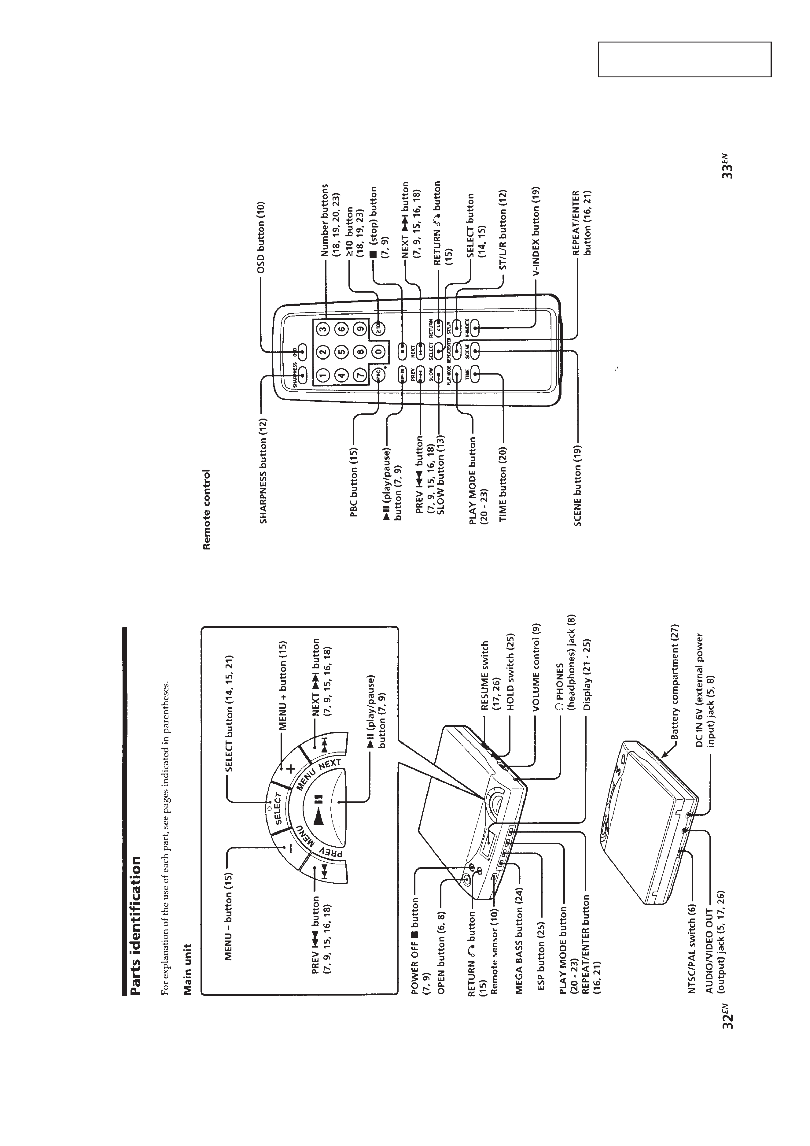
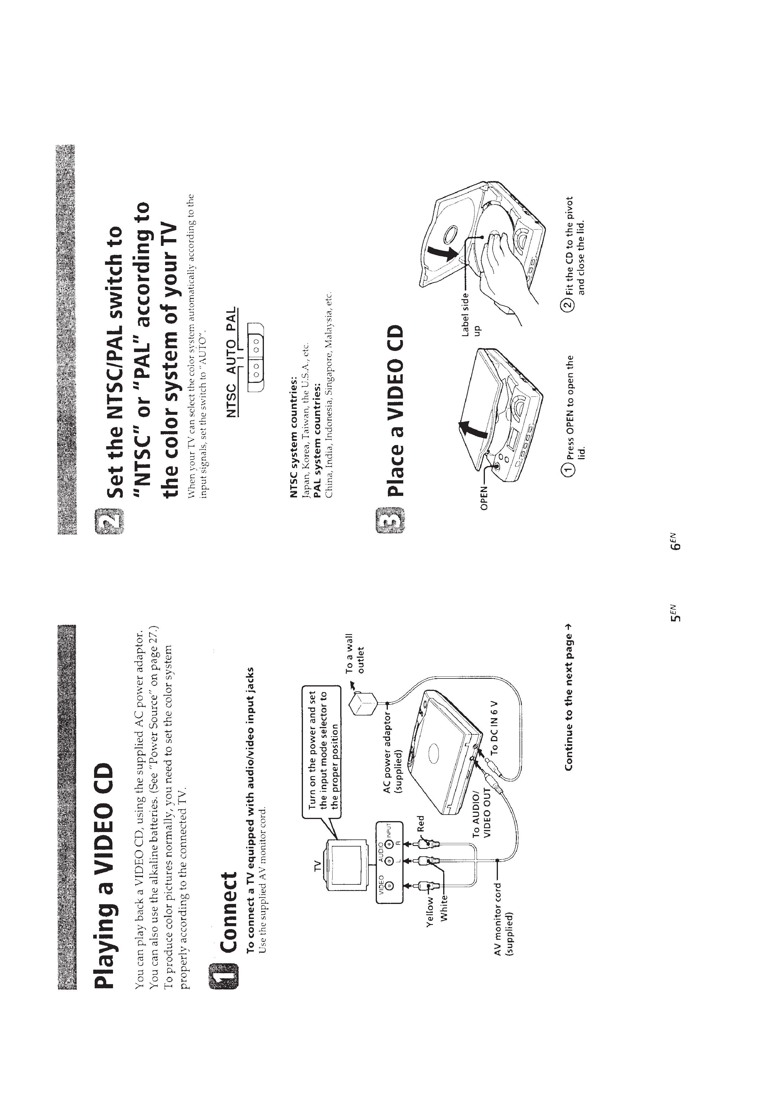
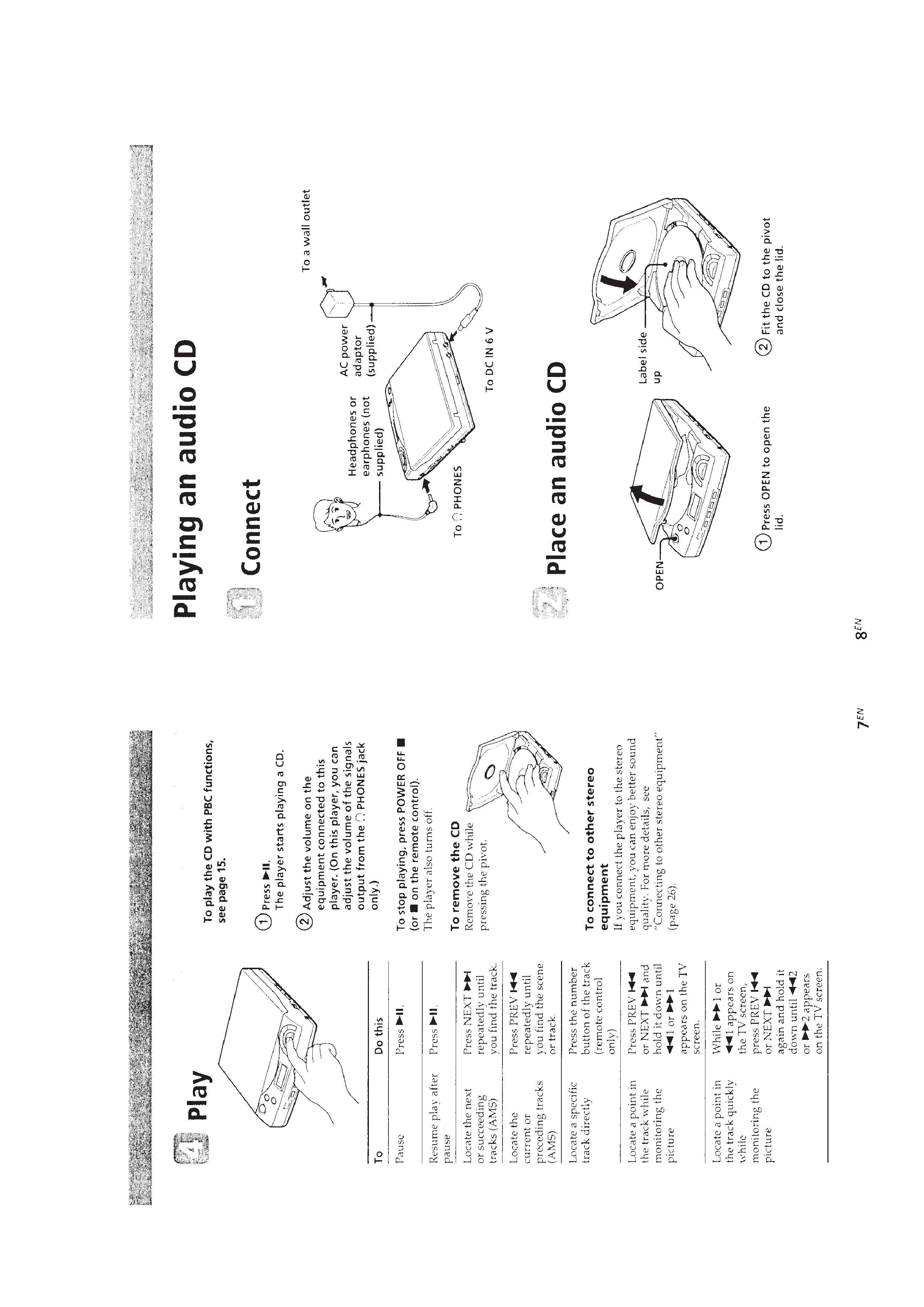
This section is extracted from
instruction manual.
4
5