Ver 1.1 1999.09
With SUPPLEMENT 1
(9-926-996-81)
MICROFILM
D-V55
SERVICE MANUAL
PORTABLE VIDEO CD PLAYER
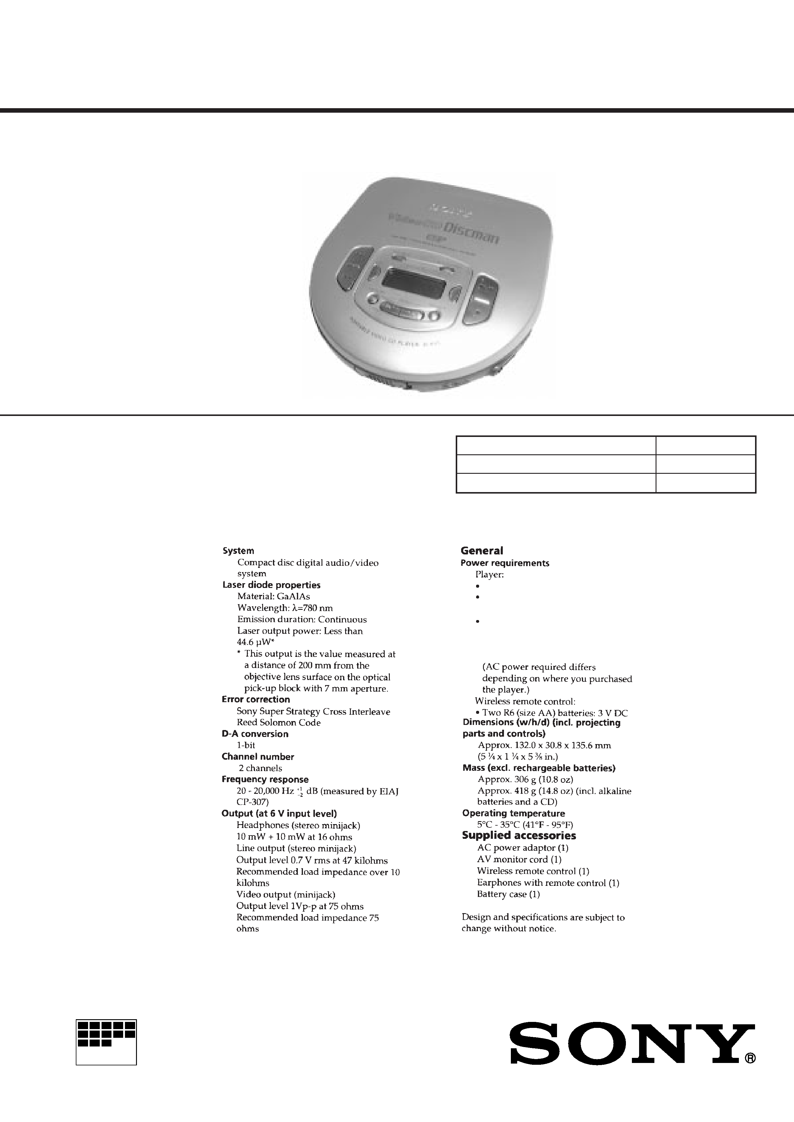
SPECIFICATIONS
E Model
Chinese Model
Model Name Using Similar Mechanism
NEW
CD Mechanism Type
CDM-2901ABA
Optical Pick-up Type
DAX-01A2
Two LR6 (size AA) batteries:3VDC
Battery case (External Batteries):
Two LR6 (size AA) batteries:3VDC
AC power adaptor (DC IN 6V jack):
220-230 V, 50/60Hz
220 V, 50Hz
220 V, 50/60Hz
2
Specifications ........................................................................... 1
1. SERVICING NOTE ....................................................... 3
2. GENERAL
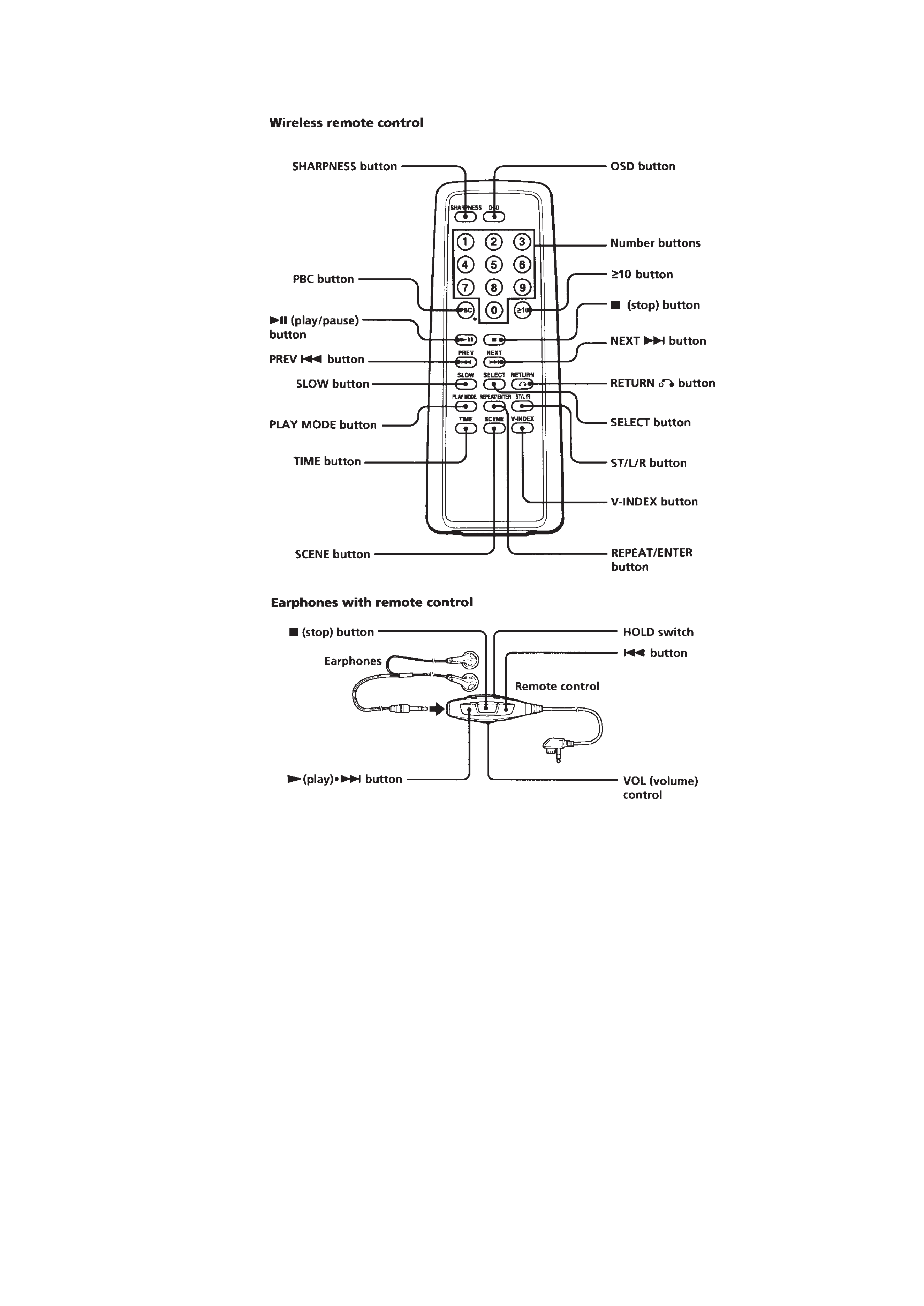
Location and Function of Controls .................................... 4
3. DISASSEMBLY
3-1. Cabinet (Lower) Sub ASSY ....................................... 6
3-2. Lid Sub ASSY, Switch Unit ........................................ 6
3-3. MPEG Board .............................................................. 7
3-4. MD ASSY, IR Board .................................................. 7
3-5. Main Board ................................................................. 8
3-6. Turn Table Motor ASSY (Spindle) (M902),
Optical Pick-up (DAX-01A2),
Sled Motor ASSY (M901) .......................................... 8
4. SERVICE MODE (TEST MODE)
4-1. How to Enter the Test Mode ....................................... 9
4-2. How to Release the Test Mode ................................... 9
4-3. Each Key Function in Test Mode ............................... 9
5. ELECTRICAL ADJUSTMENTS
5-1. Precautions for Adjustment ...................................... 10
5-2. Before Beginning Adjustment .................................. 10
5-3. Tracking Balance Check ........................................... 10
5-4. Focus Bias Check ...................................................... 11
6. DIAGRAMS
6-1. Explanation of IC Terminals ..................................... 12
6-2. Block Diagram .......................................................... 19
6-3. Printed Wiring Boards (Main Section) ..................... 23
6-4. Schematic Diagram (Main Section) ......................... 27
6-5. Schematic Diagram (MPEG Section) ....................... 34
6-6. Printed Wiring Boards (MPEG Section) .................. 37
7. EXPLODED VIEWS
7-1. Cabinet (Upper) Section ........................................... 42
7-2. Cabinet (Lower) Section ........................................... 43
7-3. Optical Pick-up Section (CDM-2901ABA) ............. 44
8. ELECTRICAL PARTS LIST ................................ 45
SAFETY-RELATED COMPONENT WARNING!!
COMPONENTS IDENTIFIED BY MARK
! OR DOTTED LINE WITH
MARK
!ON THE SCHEMATIC DIAGRAMS AND IN THE PARTS
LIST ARE CRITICAL TO SAFE OPERATION.
REPLACE THESE COMPONENTS WITH SONY PARTS WHOSE
PART NUMBERS APPEAR AS SHOWN IN THIS MANUAL OR IN
SUPPLEMENTS PUBLISHED BY SONY.
Flexible Circuit Board Repairing
· Keep the temperature of the soldering iron around 270°C during
repairing.
· Do not touch the soldering iron on the same conductor of the
circuit board (within 3 times).
· Be careful not to apply force on the conductor when soldering or
unsoldering.
Notes on chip component replacement
· Never reuse a disconnected chip component.
· Notice that the minus side of a tantalum capacitor may be dam-
aged by heat.
TABLE OF CONTENTS
This Compact Disc player is
classified as a CLASS 1 LASER
product.
The CLASS 1 LASER
PRODUCT label is located on the
bottom exterior.
CAUTION
Use of controls or adjustments or performance of procedures other than
those specified herein may result in hazardous radiation exposure.
DANGER
Invisible laser radiation when open and interlock failed or defeated.
Avoid direct exposure to beam.
3
SECTION 1
SERVICING NOTE
NOTES ON HANDLING THE OPTICAL PICK-UP
BLOCK OR BASE UNIT
The laser diode in the optical pick-up block may suffer electro-
static breakdown because of the potential difference generated by
the charged electrostatic load, etc. on clothing and the human
body. During repair, pay attention to electrostatic breakdown and
also use the procedure in the printed matter which is included in
the repair parts.
The flexible board is easily damaged and should be handled with
care.
NOTES ON LASER DIODE EMISSION CHECK
The laser beam on this model is concentrated so as to be focused
on the disc reflective surface by the objective lens in the optical
pick-up block. Therefore, when checking the laser diode emis-
sion, observe from more than 30cm away from the objective lens.
Before Replacing the Optical pick-up Block
Please be sure to check thoroughly the parameters as per the
"Optical pick-up Block Checking Procedure" (Part No. : 9-960-
027-11) issued separately before replacing the optical Pick-up
block.
Note and specifications required to check are given below.
· FOK output : IC601 ((£ pin (FOK).
When checking FOK, remove the lead wire to disc motor.
· S curve P-to-P value : 1.2 2Vp-p IC501 !§ pin.
When checking S curve P-to-P value, remove the lead wire to
disc motor.
· RF signal P-to-P value : 0.5 0.9Vp-p
· Traverse signal P-to-P value : 1.2 2.0Vp-p
· The repairing grating holder is impossible.
Laser Diode Checking Methods
During normal operation of the equipment, emission of the laser
diode is prohibited unless the upper panel is closed while turning
ON the S804 (push switch type).
The following two checking methods for the laser diode are
operable.
Method-1 (In the service mode or normal operation) :
Emission of the laser diode is visually checked.
1. Open the upper lid.
2. Push the S804 as shown in Fig. 1-1.
3. Press the
fl key.
4. Check the object lens for confirming normal emission of the
laser diode. If not emitting, there is a trouble in the automatic
power control circuit or the optical pick-up. During normal
operation, the laser diode is turned ON about 2.5 seconds for
focus searching.
Method-2 (In the service mode or normal operation) :
Check the value of current flowing in the laser diode.
1. Remove the upper panel.
2. Read the current printed on the rear side of the optical pick-up.
(Print on the rear side of the optical pick-up)
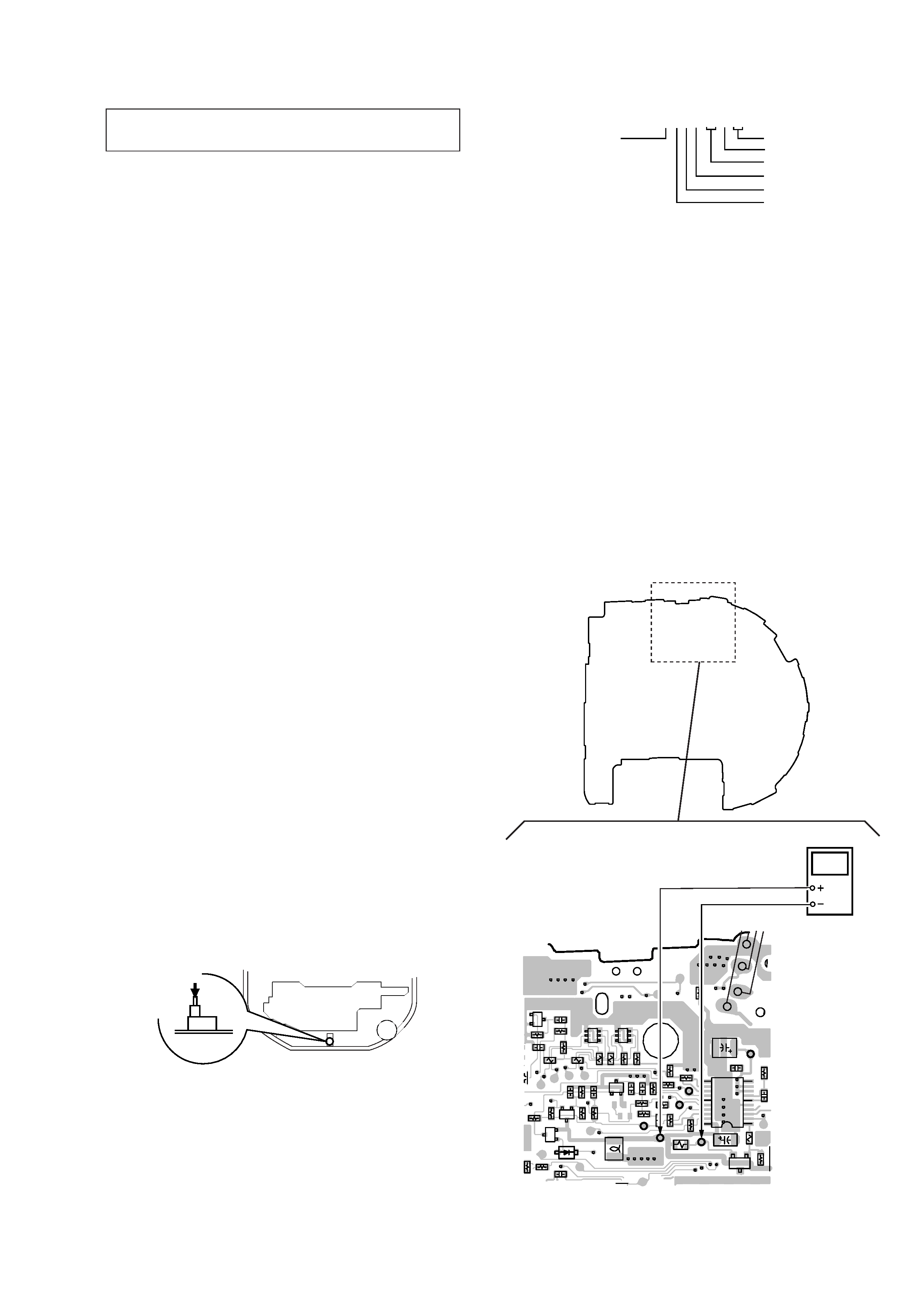
Fig.1-1 Method to push S804
AC2211397
year
version
month
A : less than 48 mA
current value
date
line No.
shift No.
Fig. 1-2 Digital Voltmeter Connecting Location
[MAIN BOARD] (SIDE B)
4
3
2
1
5
6
4
3
2
1
5
6
1
5
10
11
20
BC
E
B
C
E
B
C
E
BCE
BCE
R532
C525
C526
R751
C518
D501
C516
R544
L506
R518
IC501
R520
R531
R522
R542
R514
C530
C507
R515
R513
R525
C522
C529
R512
R516
R543
C502
Q504
R510
Q506
Q502
R509
C509
R506
R554
R528
R507
R511
R521
R519
R517
R526
Q501
C519
R523
Q503
Q507
C508
R527
TP512
TP520
TP534
TP540
TP537
TP531
TP536
TP524
TP535(RFO)
TP522
(FE)
TP523 (TE)
TP508
(VC)
TP521
TP752
TP810
TP809
TP530
TP525
15
TP524
digital voltmeter
TP520
S804
3. Connect a digital voltmeter as shown in Fig. 1-2
4. Press the
fl key.
5. Calculate the current value by the reading of the digital
voltmeter.
Reading of the digital voltmeter V ÷ 4.7
= current value (A)
(Example) Reading of the digital voltmeter of 0.2256 V :
0.2256 V ÷ 4.7
= 0.048 (A) = 48 mA
6. Check that the current value is within the following range.
+5
· Current value of the label -11 mA(25°C)
Variation by temperature : 0.4mA / °C
Current increases with temperature increased.
Current decreases with temperature decreased.
If the current is more than the range above, there is a trouble
in the automatic power control circuit or the laser diode is in
deterioration.
If less than the range, a trouble exists in the automatic power
control circuit or the optical pick-up.
4
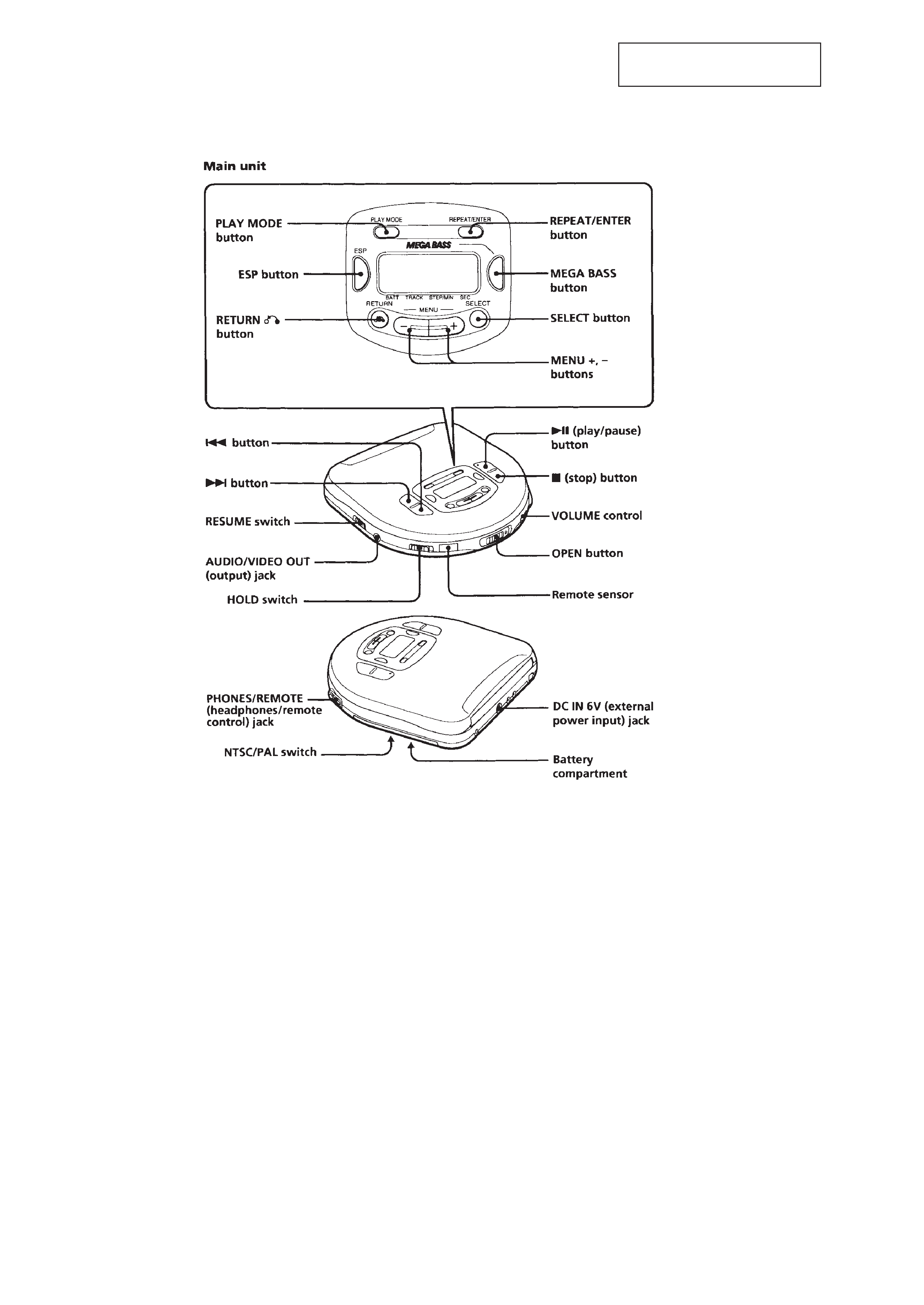
SECTION 2
GENERAL
This section is extracted from
instruction manual.
LOCATION AND FUNCTION OF CONTROLS
5