SERVICE MANUAL
SERVICE MANUAL
C MECHANISM
-- Continued on next page --
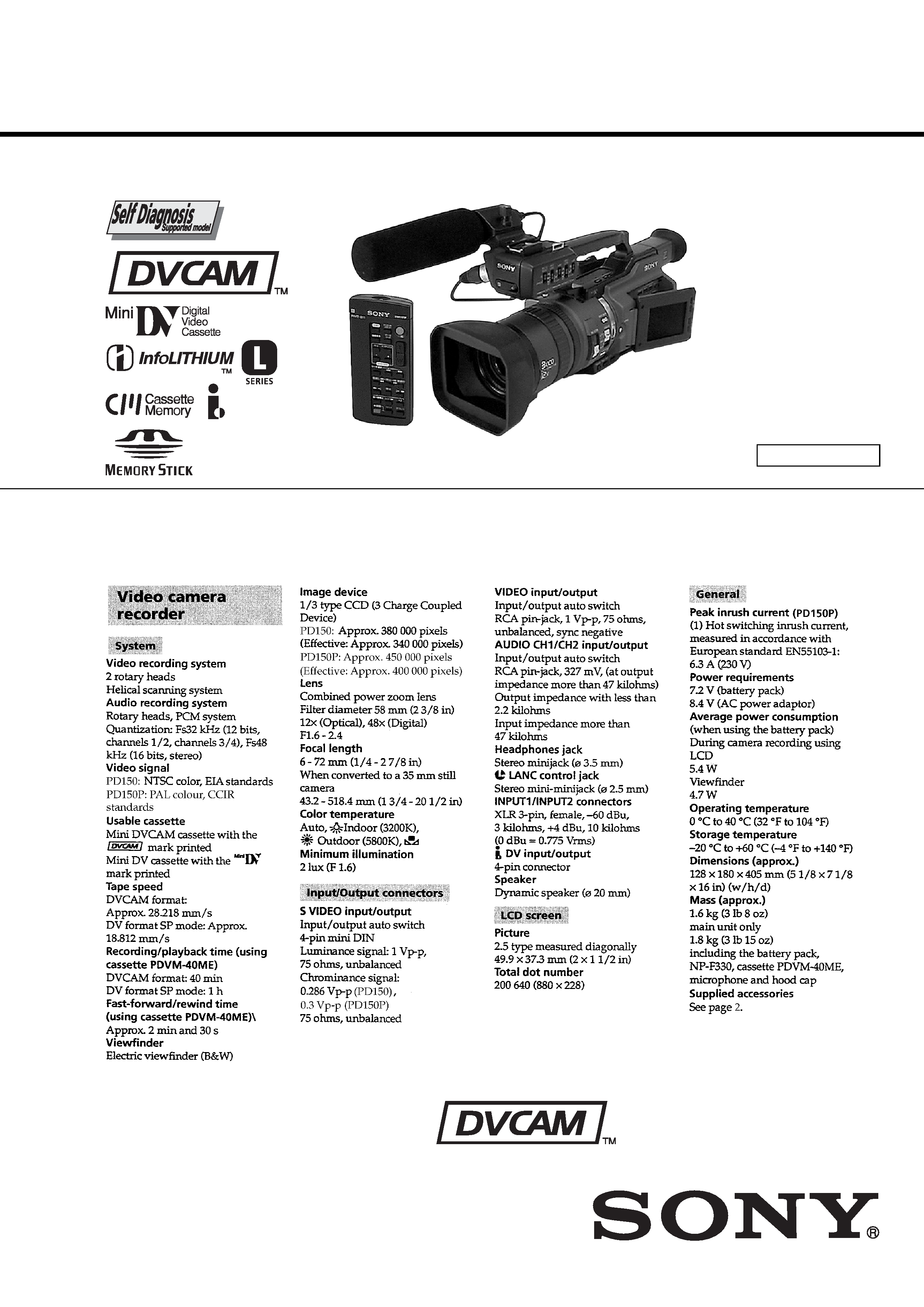
Photo : DSR-PD150
US Model
Canadian Model
DSR-PD150
AEP Model
Chinese Model
DSR-PD150P
DIGITAL CAMCORDER
SPECIFICATIONS
NTSC model : DSR-PD150
PAL model
: DSR-PD150P
DSR-PD150/PD150P
RMT-811
Ver 1.9 2004. 07
-- 2 --
1.
Check the area of your repair for unsoldered or poorly-soldered
connections. Check the entire board surface for solder splashes
and bridges.
2.
Check the interboard wiring to ensure that no wires are
"pinched" or contact high-wattage resistors.
3.
Look for unauthorized replacement parts, particularly
transistors, that were installed during a previous repair. Point
them out to the customer and recommend their replacement.
4.
Look for parts which, through functioning, show obvious signs
of deterioration. Point them out to the customer and
recommend their replacement.
5.
Check the B+ voltage to see it is at the values specified.
6.
Flexible Circuit Board Repairing
· Keep the temperature of the soldering iron around 270°C
during repairing.
· Do not touch the soldering iron on the same conductor of the
circuit board (within 3 times).
· Be careful not to apply force on the conductor when soldering
or unsoldering.
SAFETY CHECK-OUT
After correcting the original service problem, perform the following
safety checks before releasing the set to the customer.
SAFETY-RELATED COMPONENT WARNING!!
COMPONENTS IDENTIFIED BY MARK 0 OR DOTTED LINE WITH
MARK 0 ON THE SCHEMATIC DIAGRAMS AND IN THE PARTS
LIST ARE CRITICAL TO SAFE OPERATION. REPLACE THESE
COMPONENTS WITH SONY PARTS WHOSE PART NUMBERS
APPEAR AS SHOWN IN THIS MANUAL OR IN SUPPLEMENTS
PUBLISHED BY SONY.
ATTENTION AU COMPOSANT AYANT RAPPORT
À LA SÉCURITÉ!
LES COMPOSANTS IDENTIFÉS PAR UNE MARQUE 0 SUR LES
DIAGRAMMES SCHÉMATIQUES ET LA LISTE DES PIÈCES SONT
CRITIQUES POUR LA SÉCURITÉ DE FONCTIONNEMENT. NE
REMPLACER CES COMPOSANTS QUE PAR DES PIÈSES SONY
DONT LES NUMÉROS SONT DONNÉS DANS CE MANUEL OU
DANS LES SUPPÉMENTS PUBLIÉS PAR SONY.
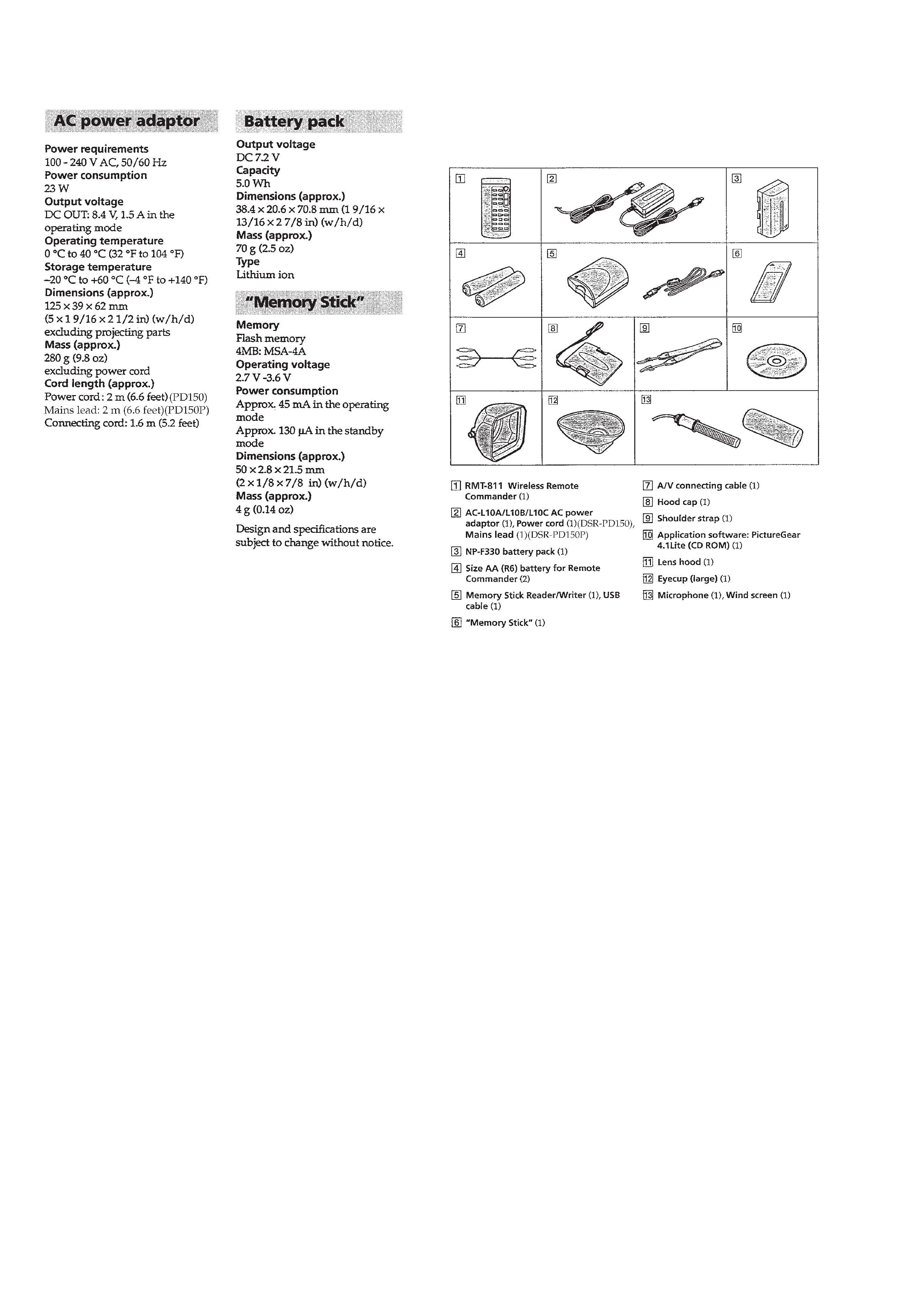
· SUPPLIED ACCESSORIES
Check that the following accessories are supplied with your
camcorder.

-- 3 --
TABLE OF CONTENTS
SERVICE NOTE
1.
POWER SUPPLY DURING REPAIRS ····························· 7
2.
TO TAKE OUT A CASSETTE WHEN NOT EJECT
(FORCE EJECT) ································································ 7
SELF-DIAGNOSIS FUNCTION
1.
SELF-DIAGNOSIS FUNCTION ······································· 8
2.
SELF-DIAGNOSIS DISPLAY ·········································· 8
3.
SERVICE MODE DISPLAY ············································· 8
3-1.
Display Method ·································································· 8
3-2.
Switching of Backup No. ··················································· 8
3-3.
End of Display ···································································· 8
4.
SELF-DIAGNOSIS CODE TABLE ··································· 9
1.
GENERAL
Quick Start Guide ······································································ 1-1
Getting started ··········································································· 1-1
Using this manual ·································································· 1-1
Checking supplied accessories ·············································· 1-2
Step 1 Inserting the microphone ············································ 1-2
Step 2 Preparing the power supply ········································ 1-2
Step 3 Inserting a cassette ······················································ 1-3
Recording Basics ····································································· 1-4
Recording a picture ································································ 1-4
Shooting backlit subjects (BACK LIGHT) ·························· 1-5
Spot light ·············································································· 1-6
Checking the recording END SEARCH/
EDIT SEARCH/Rec Review ··············································· 1-6
Playback Basics ······································································· 1-6
Playing back a tape ································································ 1-6
Viewing the recording on TV ················································ 1-7
Advanced Recording Operations ··············································· 1-8
Recording a still image on a tape Tape Photo recording ····· 1-8
Shooting with all the pixels PROG. SCAN ························· 1-8
Using the guide frame ···························································· 1-8
Using the wide mode ····························································· 1-9
Using the fader function ························································ 1-9
Using special effects Digital effect ······································ 1-9
Shooting with manual adjustment ······································· 1-10
Adjusting the white balance ················································· 1-12
Adjusting recording level manually Sound recording level ·· 1-13
Connecting an optional external microphone ·························· 1-13
Presetting the adjustment for picture quality Custom preset ·· 1-14
Focusing manually ······························································· 1-14
Interval recording ································································· 1-14
Frame by frame recording Cut recording ·························· 1-15
Superimposing the date and time on a picture ····················· 1-15
Marking an Index ································································· 1-15
Advanced Playback Operations ··············································· 1-16
Searching for a recording by index Index search ·············· 1-16
Searching the boundaries of recorded tape by title
Title search ········································································· 1-16
Searching a recording by date Date search ························ 1-16
Searching for a photo Photo search/Photo scan ················· 1-17
Playing back a tape with digital effects ······························· 1-17
Editing ····················································································· 1-18
Dubbing a tape ····································································· 1-18
Dubbing only desired scenes Digital program editing ········· 1-18
Using with analog video unit and a PC
Signal convert function ····················································· 1-20
Recording video or TV programs ········································ 1-20
Audio dubbing ····································································· 1-21
Setting time values ······························································· 1-22
Superimposing a title ··························································· 1-23
Making your own titles ························································ 1-24
Labeling a cassette ······························································· 1-25
Erasing the cassette memory data ········································ 1-25
Customizing Your Camcorder ················································· 1-26
Changing the menu settings ················································· 1-26
Resetting the date and time ·················································· 1-28
"Memory Stick" Operations ···················································· 1-28
Using a "Memory Stick" introduction ······························· 1-28
Recording still images on a "Memory Stick"
Memory Photo recording ··················································· 1-29
Superimposing a still picture in a "Memory Stick"
on a moving picture MEMORY MIX ································ 1-30
Recording an image from a tape as a still image ················· 1-31
Copying still images from a tape Photo save ····················· 1-31
Viewing a still picture Memory photo playback ················ 1-32
Copying an image recorded on a "Memory Stick" to tapes ··· 1-33
Playing back images continuously SLIDE SHOW ··············· 1-33
Preventing accidental erasure Image protection ················ 1-33
Deleting images ··································································· 1-34
Writing a print mark Print mark ········································ 1-34
Additional Information ···························································· 1-35
Compativility of DVCAM and DV formats ························ 1-35
Usable cassettes ··································································· 1-35
About i.LINK ······································································· 1-36
Troubleshooting ··································································· 1-36
Self-diagnosis display ·························································· 1-37
Warning indicators and messages ········································ 1-38
Using your camcorder abroad ·············································· 1-38
Maintenance information and precautions ··························· 1-38
Quick Reference ······································································ 1-40
Identifying the parts and controls ········································ 1-40
Quick Function Guide ························································· 1-42
Auto Logo Insert for Copyright Protection ····························· 1-43
Introduction Auto Logo Insert ··········································· 1-43
Preparing a logo file ····························································· 1-43
Registering your password ·················································· 1-43
Registering a still image to be used as a logo ······················ 1-44
Deactivating the auto logo insert function ··························· 1-44
Changing or resetting the setup ··········································· 1-45
Precautions concerning the auto logo insert function ·········· 1-45
2.
DISASSEMBLY
2-1.
LCD SECTION (HL-011, PD-126 BOARDS,
INVERTER TRANSFORMER UNIT) ··························· 2-2
2-2.
EVF SECTION (LB-065D BOARD) ······························ 2-3
2-3.
UPPER HANDLE BLOCK ASSEMBLY ······················· 2-4
2-4.
FK-076, MA-386D BOARDS ········································· 2-4
2-5.
XD-001, XS-001, XM-001 BOARDS ····························· 2-5
2-6.
CABINET (L) BLOCK ASSEMBLY, MECHANISM
DECK, VC-242D, DD-138D, JK-190 BOARDS
(FOR FORCE EJECT OF CASSETTE AND VTR
SECTION CHECK) ························································ 2-6
2-7.
CABINET (R) BLOCK ASSEMBLY ····························· 2-8
2-8.
CABINET BOTTOM (D) ASSEMBLY ·························· 2-8
2-9.
BATTERY PANEL BLOCK ASSEMBLY
(MK-014, KP-010, MS-049 BOARDS) ·························· 2-9
2-10. EVF BLOCK ASSEMBLY ············································· 2-9
2-11. LA-026, DD-138D, VC-242D, JK-190 BOARDS,
MECHANISM DECK ··················································· 2-10
2-12. LENS BLOCK ASSEMBLY, CENTER FRAME
ASSEMBLY ·································································· 2-11
2-13. CD-254, SE-108 BOARDS, ZOOM LENS
ASSEMBLY ·································································· 2-12
2-14. CONTROL SWITCH BLOCK (PS-4980),
CONTROL SWITCH BLOCK (CF-4980) ··················· 2-12
2-15. CK-093 BOARD ··························································· 2-13
2-16. CONTROL SWITCH BLOCK (ED-4980),
HINGE ASSEMBLY ····················································· 2-14
2-17. CIRCUIT BOARDS LOCATION ································· 2-15
2-18. FLEXIBLE BOARDS LOCATION ······························ 2-16

-- 4 --
3.
BLOCK DIAGRAMS
3-1.
OVERALL BLOCK DIAGRAM (1/4) ··························· 3-1
3-2.
OVERALL BLOCK DIAGRAM (2/4) ··························· 3-3
3-3.
OVERALL BLOCK DIAGRAM (3/4) ··························· 3-5
3-4.
OVERALL BLOCK DIAGRAM (4/4) ··························· 3-7
3-5.
POWER BLOCK DIAGRAM (1/3) ································ 3-9
3-6.
POWER BLOCK DIAGRAM (2/3) ······························ 3-11
3-7.
POWER BLOCK DIAGRAM (3/3) ······························ 3-13
4.
PRINTED WIRING BOARDS AND
SCHEMATIC DIAGRAMS
4-1.
FRAME SCHEMATIC DIAGRAM (1/3) ······················· 4-1
FRAME SCHEMATIC DIAGRAM (2/3) ······················· 4-3
FRAME SCHEMATIC DIAGRAM (3/3) ······················· 4-5
4-2.
PRINTED WIRING BOARDS AND
SCHEMATIC DIAGRAMS ············································ 4-8
· CD-254 (CCD IMAGER)
SCHEMATIC DIAGRAM ······························ 4-9
· CD-254 (CCD IMAGER)
PRINTED WIRING BOARD ······················· 4-11
· VC-242D (S/H AGC, TG)(1/18)
SCHEMATIC DIAGRAM ···························· 4-13
· VC-242D (CAMERA SIGNAL PROCESS)(2/18)
SCHEMATIC DIAGRAM ···························· 4-15
· VC-242D (MS I/F)(3/18)
SCHEMATIC DIAGRAM ···························· 4-17
· VC-242D (RS 232C I/F, STILL CONTROL)(4/18)
SCHEMATIC DIAGRAM ···························· 4-19
· VC-242D (MS DRIVE)(5/18)
SCHEMATIC DIAGRAM ···························· 4-21
· VC-242D (DV SIGNAL PROCESS)(6/18)
SCHEMATIC DIAGRAM ···························· 4-23
· VC-242D (DV INTERFACE)(7/18)
SCHEMATIC DIAGRAM ···························· 4-25
· VC-242D (REC/PB AMP)(8/18)
SCHEMATIC DIAGRAM ···························· 4-27
· VC-242D (LINE IN/OUT)(9/18)
SCHEMATIC DIAGRAM ···························· 4-29
· VC-242D (LINE A/D)(10/18)
SCHEMATIC DIAGRAM ···························· 4-31
· VC-242D (RGB DRIVE/TG)(11/18)
SCHEMATIC DIAGRAM ···························· 4-33
· VC-242D (CAMERA CONTROL)(12/18)
SCHEMATIC DIAGRAM ···························· 4-35
· VC-242D (MECHANISM CONTROL)(13/18)
SCHEMATIC DIAGRAM ···························· 4-37
· VC-242D (DRUM/CAPSTAN MOTOR DRIVE)(14/18)
SCHEMATIC DIAGRAM ···························· 4-39
· FP-594 (LOADING MOTOR, S/T REEL SENSOR)
PRINTED WIRING BOARD ······················· 4-41
· VC-242D (HI CONTROL)(15/18)
SCHEMATIC DIAGRAM ···························· 4-43
· VC-242D (AU LINE A/D, D/A)(16/18)
SCHEMATIC DIAGRAM ···························· 4-45
· VC-242D (LINE AMP)(17/18)
SCHEMATIC DIAGRAM ···························· 4-47
· VC-242D (CONNECTOR)(18/18)
SCHEMATIC DIAGRAM ···························· 4-49
· VC-242D (S/H AGC, TG, CAMERA SIGNAL
PROCESS, MS I/F, RS232C I/F, STILL CONTROL,
MS DRIVE, DV SIGNAL PROCESS, REC/PB AMP,
LINE IN/OUT, LINE A/D, RGB DRIVE/TG,
CAMERA CONTROL, MECHANISM CONTROL,
DRUM/CAPSTAN MOTOR DRIVE, HI CONTROL,
AU LINE A/D, D/A, LINE AMP)
PRINTED WIRING BOARD ······················· 4-51
· JK-190 (JACK BOARD)
PRINTED WIRING BOARD ······················· 4-55
· JK-190 (JACK BOARD)
SCHEMATIC DIAGRAM ···························· 4-57
· CK-093 (KEY IN)
PRINTED WIRING BOARD ······················· 4-59
· CK-093 (KEY IN)
SCHEMATIC DIAGRAM ···························· 4-61
· PD-126 (RGB DRIVE/TG)
PRINTED WIRING BOARD ······················· 4-63
· PD-126 (RGB DRIVE/TG)
SCHEMATIC DIAGRAM ···························· 4-65
· LA-026 (ZOOM/FOCUS DRIVE, VAP DRIVE,
KEY IN/CONNECTOR)
PRINTED WIRING BOARD ······················· 4-67
· LA-026 (ZOOM/FOCUS DRIVE)(1/3)
SCHEMATIC DIAGRAM ···························· 4-69
· LA-026 (VAP DRIVE)(2/3)
SCHEMATIC DIAGRAM ···························· 4-71
· LA-026 (KEY IN/CONNECTOR)(3/3)
SCHEMATIC DIAGRAM ···························· 4-73
· SE-108 (VAP SENSOR)
PRINTED WIRING BOARD ······················· 4-75
· MS-049 (MS CONNECTOR)
PRINTED WIRING BOARD ······················· 4-77
· KP-010 (SELECT DIAL)
PRINTED WIRING BOARD ······················· 4-79
· MK-014 (CONTROL KEY)
PRINTED WIRING BOARD ······················· 4-79
· KP-010 (LCD DRIVE), MK-014 (CONTROL KEY),
MS-049 (MS CONNECTOR)
SCHEMATIC DIAGRAM ···························· 4-81
· FK-076 (CONTROL SWITCH)
PRINTED WIRING BOARD ······················· 4-83
· FK-076 (CONTROL SWITCH)
SCHEMATIC DIAGRAM ···························· 4-85
· XD-001 (DC/DC CONVERTER SIRCS),
XS-001 (MIC SELECT)
PRINTED WIRING BOARDS ····················· 4-87
· XD-001 (DC/DC CONVERTER SIRCS),
XS-001 (MIC SELECT)
SCHEMATIC DIAGRAM ···························· 4-89
· XM-001 (MIC AMP)
PRINTED WIRING BOARD ······················· 4-91
· XM-001 (MIC AMP)
SCHEMATIC DIAGRAM ···························· 4-93
· LB-065D (BACK LIGHT)
PRINTED WIRING BOARD ······················· 4-96
· LB-065D (BACK LIGHT)
SCHEMATIC DIAGRAM ···························· 4-97
· HL-011 (LCD DRIVE)
PRINTED WIRING BOARD ······················· 4-99
· HL-011 (LCD DRIVE)
SCHEMATIC DIAGRAM ·························· 4-101
· MA-386D (AUDIO AMP)
PRINTED WIRING BOARD ····················· 4-103
· MA-386D (AUDIO AMP)
SCHEMATIC DIAGRAM ·························· 4-105
· DD-138D (DC/DC CONVERTER, DC REGURATOR)
PRINTED WIRING BOARD ····················· 4-107
· DD-138D (DC/DC CONVERTER)(1/2)
SCHEMATIC DIAGRAM ·························· 4-109
· DD-138D (DC REGURATOR)(2/2)
SCHEMATIC DIAGRAM ·························· 4-111
4-3.
WAVEFORMS ···························································· 4-113
4-4.
MOUNTED PARTS LOCATION ······························· 4-118

-- 5 --
5
ADJUSTMENTS
1.
Before starting adjustment ··············································· 5-1
1-1.
Adjusting items when replacing main parts and boards. · 5-2
5-1.
CAMERA SECTION ADJUSTMENT ··························· 5-4
1-1.
PREPARATIONS BEFORE ADJUSTMENT
(CAMERA SECTION) ··················································· 5-4
1-1-1. List of Service Tools ························································ 5-4
1-1-2. Preparations ····································································· 5-6
1-1-3. Precaution ········································································ 5-8
1.
Setting the Switch ···························································· 5-8
2.
Order of Adjustments ······················································ 5-8
3.
Subjects ··········································································· 5-8
1-2.
INITIALIZATION OF A, B, C, D, E, F, 8 PAGE DATA ··· 5-9
1-2-1. INITIALIZATION OF A, C, D, 8 PAGE DATA ············· 5-9
1.
Initializing the C, D, 8 Page Data ···································· 5-9
2.
Modification of C, D, 8 Page Data ·································· 5-9
3.
C Page Table ···································································· 5-9
4.
D Page Table ·································································· 5-11
5.
8 Page Table ··································································· 5-12
6.
Initializing the A Page Data ··········································· 5-12
1-2-2. INITIALIZATION OF B PAGE DATA ························· 5-13
1.
Initializing the B Page Data ··········································· 5-13
2.
Modification of B Page Data ········································· 5-13
3.
B Page Table ·································································· 5-13
1-2-3. INITIALIZATION OF E, F PAGE DATA ····················· 5-14
1.
Initializing the E, F Page Data ······································· 5-14
2.
Modification of E, F Page Data ····································· 5-14
3.
Modification of E Page Data ········································· 5-14
4.
F Page Table ·································································· 5-15
5.
E Page Table ·································································· 5-16
1-3.
CAMERA SYSTEM ADJUSTMENTS ························ 5-17
1.
27MHz Origin Oscillation Adjustment
(VC-242D board) ·························································· 5-17
2.
Zoom Key Center Adjustment ······································· 5-17
3.
HALL Adjustment ························································· 5-18
4.
Offset Adjustment ·························································· 5-18
5.
Flange Back Adjustment (Using Minipattern Box) ······· 5-19
6.
Flange Back Adjustment
(Using Flange Back Adjustment Chart and Subject
More Than 500m Away) ··············································· 5-20
6-1.
Flange Back Adjustment (1) ·········································· 5-20
6-2.
Flange Back Adjustment (2) ·········································· 5-20
7.
Flange Back Check ························································ 5-21
8.
Picture Frame Setting ···················································· 5-21
9.
Pre White Balance Data Input ······································· 5-22
10.
Auto White Balance Standard Data Input ····················· 5-22
11.
MAX GAIN Adjustment ··············································· 5-23
12.
LV Standard Data Input ················································· 5-23
13.
White Balance ND Filter 1 Compensation ···················· 5-24
14.
White Balance ND Filter 2 Compensation ···················· 5-24
15.
Auto White Balance Adjustment ··································· 5-25
16.
Color Reproduction Adjustment (ND Filter OFF) ········ 5-25
17.
Color Reproduction Adjustment (ND Filter 1) ·············· 5-26
18.
Color Reproduction Adjustment (ND Filter 2) ·············· 5-26
19.
White Balance Check ···················································· 5-27
20.
Steady Shot Adjustment ················································ 5-28
20-1. Steady Shot Adjustment (1) ··········································· 5-29
20-2. Steady Shot Adjustment (2) ··········································· 5-30
1-4.
ELECTRONIC VIEWFINDER SYSTEM
ADJUSTMENT ····························································· 5-31
1.
VCO Adjustment (VC-242D board) ······························ 5-31
2.
Bright Adjustment (1) (VC-242D board) ······················ 5-32
3.
Bright Adjustment (2) (VC-242D board) ······················ 5-32
4.
Contrast Adjustment (VC-242D board) ························ 5-33
5.
Backlight Consumption Current Adjustment
(VC-242D board) ·························································· 5-33
1-5.
LCD SYSTEM ADJUSTMENT ··································· 5-34
1.
VCO Adjustment (PD-126 board) ································· 5-34
2.
Bright Adjustment (PD-126 board) ······························· 5-35
3.
Black Limit Adjustment (PD-126 board) ······················ 5-35
4.
Contrast Adjustment (PD-126 board) ···························· 5-36
5.
Center Level Adjustment (PD-126 board) ····················· 5-36
6.
V-COM Adjustment (PD-126 board) ···························· 5-37
7.
White Balance Adjustment (PD-126 board) ·················· 5-37
5-2.
MECHANICAL SECTION ADJUSTMENT ··············· 5-38
2-1.
PARTS REPLACEMENT AND PREPARATION
FOR ADJUSTMENT ···················································· 5-38
2-1-1. Outline ··········································································· 5-38
1.
Manual test ···································································· 5-38
2.
Step test ········································································· 5-38
3.
Auto test ········································································ 5-38
2-1-2. Mechanism Condition (Position) Shifting Order List ··· 5-38
2-1-3. Mode Selector II (A-6082-282-A) Connection ············· 5-38
2-1-4. The Mechanical Adjustment Requires the Following
Tools ·············································································· 5-39
2-2.
PARTS REPLACEMENT ············································· 5-40
2-2-1. Tape Fall Stopper, HC Roller and HC Arm ··················· 5-40
2-2-2. Drum Assembly and Drum Base Block Assembly ········ 5-40
2-2-3. Damper Assembly, Cassette Compartment Assembly
and Extension Spring ····················································· 5-41
2-2-4. Reel Table (S) / Reel Table (T) Assembly ····················· 5-42
2-2-5. Cassette Base Block Assembly, Gooseneck Gear
Assembly and Relay Gear ············································· 5-42
2-2-6. TG1 Adjustment Plate Assembly, Tension Coil Spring
(TG1), TG1 Arm Assembly, TG7 Retainer Spring and
TG7 Arm Block Assembly ············································ 5-43
2-2-7. Brake Slider Assembly, Pinch Slider Assembly and
Cam Gear ······································································· 5-43
2-2-8. Pinch Arm Assembly, Torsion Spring (TG7LD), Pinch
Press Arm and Eject Arm ·············································· 5-44
2-2-9. GL Block Assembly, GL Driving Gear and HC Driving
Arm ················································································ 5-44
2-2-10. Capstan Motor, Conversion Pulley, Timing Belt and
Holder ·········································································· 5-45
2-2-11. L Motor Block Assembly and FP-594 Flexible Board ·· 5-46
2-2-12. Reset Arm (S), Brake (S), Brake Rack (S), Brake (T),
Brake Gear (T), Brake Spring (T) and
Extension Spring ························································· 5-47
2-2-13. Coaster (S) / (T) Assembly, GL Arm (S) / (T) Assembly,
Guide Rail, GL Gear (S) / (T) and Torsion Spring
(GLS) / (GLT) ······························································ 5-48
2-2-14. L Motor Assembly, Motor Shield, FP-248 Flexible Board,
TG1 Spring Hook, Spring Hook Fulcrum Base,
Spring Hook Driving Arm, Worm Shaft, Deceleration
Gear and Motor Holder ··············································· 5-49
2-3.
CHECK AND ADJUSTMENT ····································· 5-50
2-3-1. FWD Position Checking and Adjustment ····················· 5-51
2-3-2. FWD Back Tension Checking and Adjustment ············· 5-51
2-2-3. Reel Table (S) / Reel Table (T) Torque Check ·············· 5-52
2-3-4. Preparation for Tape Path Checking and Adjustment ···· 5-53
2-3-5. Track Checking and Adjustment ··································· 5-54
2-3-6. TG7 Slack Checking and Adjustment ··························· 5-54
2-3-7. Curl Checking and Adjustment ····································· 5-55
2-3-8. CUE / REV Check ························································· 5-55
2-3-9. Rising Check ································································· 5-55
2-4.
PERIODIC CHECK ······················································ 5-56
2-4-1. Cleaning of Rotary Drum Assembly ····························· 5-56
2-4-2. Cleaning of Tape Path System ······································· 5-56
2-4-3. Periodic Checks ····························································· 5-56
5-3.
VIDEO SECTION ADJUSTMENTS ··························· 5-57
3-1.
PREPARATIONS BEFORE ADJUSTMENTS ············ 5-57
3-1-1. Equipment Required ······················································ 5-57