SERVICE MANUAL
US Model
Canadian Model
AEP Model
UK Model
Australian Model
New Zealand Model
DIGITAL VIDEO CASSETTE RECORDER
SPECIFICATIONS
Continued on next page
R MECHANISM
DSR-11
RMT-DS11
System
Recording format DVCAM/DV (SP) format, rotating
2-head helical scan, digital
component recording
Video signal
EIA STANDARD, NTSC color
system
CCIR STANDARD, PAL colour
system
Video
Quantification
8-bit
Standardization
frequency
NTSC:
13.5 MHz (4:1:1 Component)
PAL:
13.5 MHz (4:2:0 Component)
Audio
Quantification
12-bit (non-linear) or 16-bit (linear)
Standardization
frequency
32 kHz (12-bit recording) or
48 kHz (16-bit recording)
Usable cassettes
Standard-DVCAM cassettes and
Mini-DVCAM cassettes
Recording time
Standard cassette
DVCAM:
184 minutes (PDV184)
180 minutes (DV270)
DV: 270 minutes (PDV184/
DV270)
Mini cassette
DVCAM: 40 minutes (PDVM40/
DVM60)
DV: 60 minutes (PDVM40/
DVM60)
(We recommend that you use the
DVCAM cassettes.)
Clock
Quartz locked
Power back-up
Back-up duration: up to one month
(after a 10-hour charge)
Inputs and outputs
Video input
Phono jack
Input signal: 1 Vp-p
(75 ohms unbalanced)
Video output
Phono jack
Output signal: 1 Vp-p
(75 ohms unbalanced)
S video input
Mini DIN 4-pin
Luminance signal: 1 Vp-p
(75 ohms unbalanced)
Chrominance signal:
0.286 Vp-p (NTSC)
0.3 Vp-p (PAL)
(75 ohms unbalanced)
S video output
Mini DIN 4-pin
Luminance signal: 1 Vp-p
(75 ohms unbalanced)
Chrominance signal:
0.286 Vp-p (NTSC)
0.3 Vp-p (PAL)
(75 ohms unbalanced)
Audio input
Phono jack (L, R)
Input level: 2 Vrms (full bit)
Input impedance: more than
47 kohms
Audio output
Phono jack (L, R)
Output level: 2 Vrms (full bit)
Output impedance: less than
10 kohms
Control S input
Minijack
LANC input/output
Stereo mini-mini jack
DV input/output
4-pin jack
General
Power consumption
15 W (during playback)
Peak inrush current
Hot switching inrush current,
measured in accordance with
European standard EN55103-1:
6 A (230V)
Operating temperature
5
°C to 40 °C (41 °F to 104 °F)
Storage temperature
20
°C to +60 °C (4 °F to +140 °F)
Ver 1.3 2004. 10
2
1. Check the area of your repair for unsoldered or poorly-sol-
dered connections. Check the entire board surface for solder
splashes and bridges.
2. Check the interboard wiring to ensure that no wires are
"pinched" or contact high-wattage resistors.
3. Look for unauthorized replacement parts, particularly transis-
tors, that were installed during a previous repair. Point them
out to the customer and recommend their replacement.
4. Look for parts which, though functioning, show obvious signs
of deterioration. Point them out to the customer and recom-
mend their replacement.
SAFETY CHECK-OUT
After correcting the original service problem, perform the following
safety checks before releasing the set to the customer.
5. Check the B+ voltage to see it is at the values specified.
6. Flexible Circuit Board Repairing
·
Keep the temperature of the soldering iron around 270 °C
during repairing.
·
Do not touch the soldering iron on the same conductor of
the circuit board (within 3 times).
·
Be careful not to apply force on the conductor when sol-
dering or unsoldering.
ATTENTION AU COMPOSANT AYANT RAPPORT
À LA SÉCURITÉ!
LES COMPOSANTS IDENTIFIÉS PAR UNE MARQUE 0
SUR LES DIAGRAMMES SCHÉMATIQUES ET LA LISTE
DES PIÈCES SONT CRITIQUES POUR LA SÉCURITÉ
DE FONCTIONNEMENT. NE REMPLACER CES COM-
POSANTS QUE PAR DES PIÈCES SONY DONT LES
NUMÉROS SONT DONNÉS DANS CE MANUEL OU
DANS LES SUPPLÉMENTS PUBLIÉS PAR SONY.
SAFETY-RELATED COMPONENT WARNING!!
COMPONENTS IDENTIFIED BY MARK 0 OR DOTTED
LINE WITH MARK 0 ON THE SCHEMATIC DIAGRAMS
AND IN THE PARTS LIST ARE CRITICAL TO SAFE
OPERATION. REPLACE THESE COMPONENTS WITH
SONY PARTS WHOSE PART NUMBERS APPEAR AS
SHOWN IN THIS MANUAL OR IN SUPPLEMENTS PUB-
LISHED BY SONY.
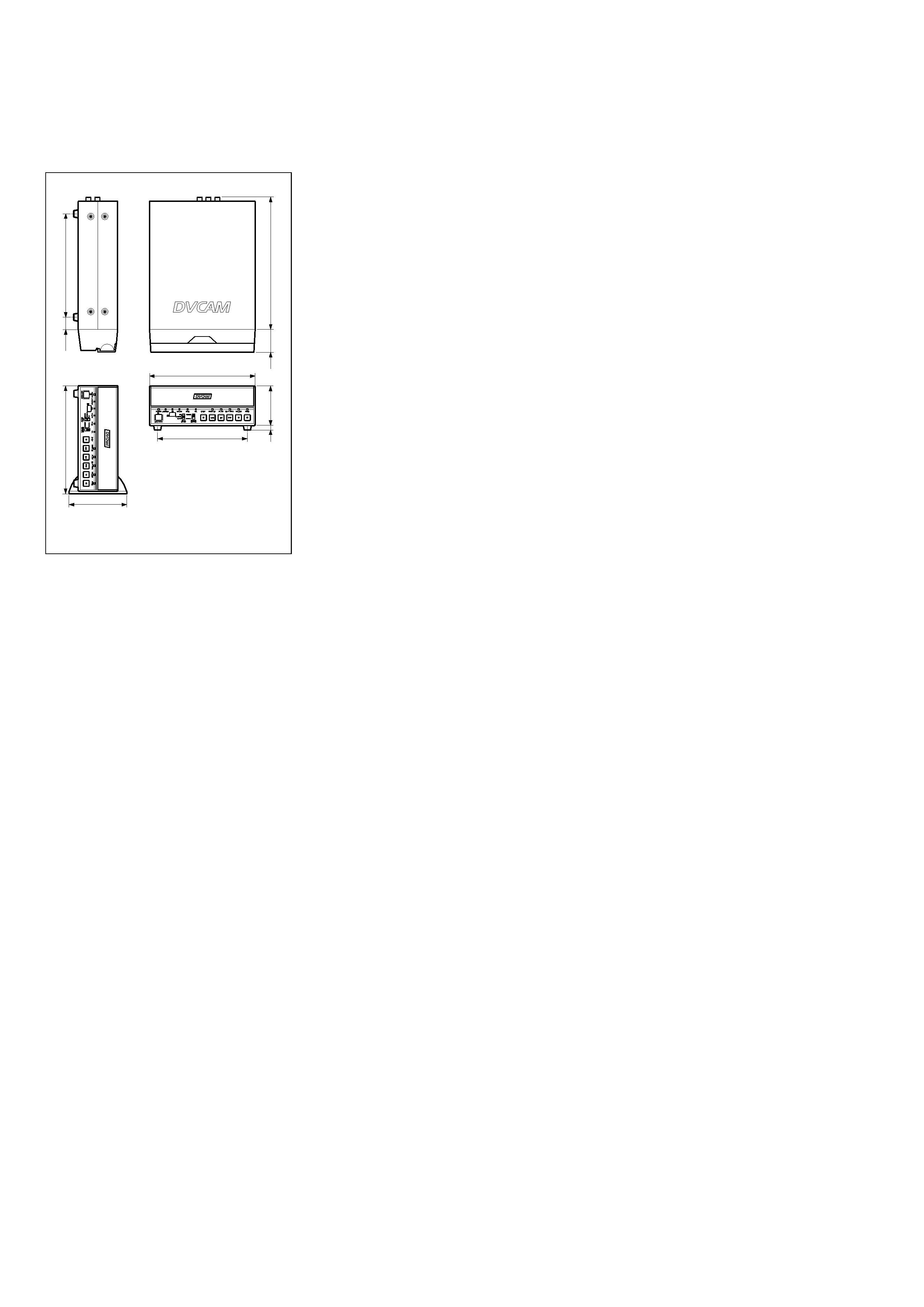
Dimensions
Approx. 180
× 73 × 265 mm
(7 1/8
× 2 7/8 × 10 1/2 inches)
(w/h/d, including projecting parts
and controls)
Mass
Approx. 2.7 kg (5 lb 15 oz)
Supplied accessories
Remote Commander (1)
Size AA (R6) batteries (2)
AC power adaptor (1)
Power cord (1)
Rack (1)
Cleaning cassette (1)
Operating instructions
Design and specifications are subject to change
without notice.
Unit: mm (inches)
184
(7
1 /
4)
18.5
(
3 /
4)
185
(7
3 /
8)
226.1
(9)
180 (7 1/8)
151 (6)
38.4
(1
9 /
16
)
4
(
3 /
16
)
69
(2
3 /
4)
110 (43/8)

3
TABLE OF CONTENTS
Section
Title
Page
Section
Title
Page
SERVICE NOTE ............................................................... 5
1.
Note for Repair ............................................................ 5
SELF-DIAGNOSIS FUNCTION ..................................... 6
1.
Self-diagnosis Function ............................................... 6
2.
Self-diagnosis Display ................................................. 6
3.
Service Mode Display ................................................. 6
4.
Self-diagnosis Code Table .......................................... 7
1.
GENERAL
Features ................................................................................ 1-1
Location and Function of Parts ............................................. 1-1
Notes on Video Cassettes ..................................................... 1-3
Preparations .......................................................................... 1-3
Playback ................................................................................ 1-4
Recording .............................................................................. 1-8
Installing the Unit Vertically ................................................... 1-9
Operating the Menus ............................................................. 1-9
Troubleshooting ..................................................................... 1-12
Alarm Messages .................................................................... 1-12
Notes on Use ......................................................................... 1-12
Compatibility of DVCAM and DV Format .............................. 1-13
2.
DISASSEMBLY
2-1.
Upper Case ................................................................. 2-1
2-2.
Front Panel Assembly ................................................. 2-1
2-3.
VD-031 Board .............................................................. 2-1
2-4.
DC/DC Converter Unit ................................................. 2-1
2-5.
HD-024 Board ............................................................. 2-2
2-6.
Mechanism Deck ......................................................... 2-2
2-7.
JC-20 Board ................................................................ 2-2
2-8.
RP-234 Board .............................................................. 2-2
2-9.
Circuit Boards Location ............................................... 2-3
3.
BLOCK DIAGRAMS
3-1.
Overall Block Diagram 1 ............................................. 3-1
3-2.
Overall Block Diagram 2 ............................................. 3-3
3-3.
Overall Block Diagram 3 ............................................. 3-5
3-4.
Overall Block Diagram 4 ............................................. 3-7
3-5.
Power Block Diagram 1 ............................................... 3-9
3-6.
Power Block Diagram 2 ............................................... 3-11
3-7.
Power Block Diagram 3 ............................................... 3-13
3-8.
Power Block Diagram 4 ............................................... 3-15
4.
PRINTED WIRING BOARDS AND
SCHEMATIC DIAGRAMS ..................................... 4-1
4-1.
Frame Schematic Diagram (1/2) ................................. 4-3
Frame Schematic Diagram (2/2) ................................. 4-5
4-2.
Printed Wiring Boards and Schematic Diagrams ....... 4-7
·
RP-234 Printed Wiring Board ................................ 4-7
·
RP-234 (REC/PB AMP 1) Schematic Diagram ..... 4-11
·
RP-234 (REC/PB AMP 2) Schematic Diagram ..... 4-13
·
JC-20 Printed Wiring Board ................................... 4-15
·
JC-20 (VIDEO PB AMP) Schematic Diagram ....... 4-19
·
JC-20 (VIDEO A/D CONVERTER)
Schematic Diagram ................................................ 4-21
·
JC-20 (CHROMA MIX) Schematic Diagram .......... 4-23
·
JC-20 (AFC) Schematic Diagram .......................... 4-25
·
JC-20 (VFD (VIDEO DSP, D/A CONVERTER))
Schematic Diagram ................................................ 4-27
·
JC-20 (SFD) Schematic Diagram .......................... 4-29
·
JC-20 (TFD) Schematic Diagram .......................... 4-31
·
JC-20 (DV INTERFACE) Schematic Diagram ....... 4-33
·
JC-20 (MECHANISM CONTROL 1)
Schematic Diagram ................................................ 4-35
·
JC-20 (MECHANISM CONTROL 2)
Schematic Diagram ................................................ 4-37
·
JC-20 (MODE CONTROL) Schematic Diagram .... 4-39
·
JC-20 (AUDIO 1) Schematic Diagram ................... 4-41
·
JC-20 (AUDIO 2) Schematic Diagram ................... 4-43
·
JC-20 (POWER SUPPLY) Schematic Diagram .... 4-45
·
VD-031 Printed Wiring Board ................................ 4-47
·
VD-031 (INTERFACE) Schematic Diagram .......... 4-51
·
VD-031 (VIDEO DECODER)
Schematic Diagram ................................................ 4-53
·
VD-031 (VIDEO OUTPUT) Schematic Diagram ... 4-55
·
VD-031 (AUDIO) Schematic Diagram ................... 4-57
·
VD-031 (Y/C SEPARATION)
Schematic Diagram ................................................ 4-59
·
HD-024 (HI CONTROL) Schematic Diagram ........ 4-61
·
HD-024 (MATRIX KEY CONTROL, LED DRIVE)
Schematic Diagram ................................................ 4-63
·
HD-024 (UVIC) Schematic Diagram ...................... 4-65
·
HD-024 (DC/DC CONVERTER, CAPSTAN MOTOR
DRIVE, CAM MOTOR DRIVE)
Schematic Diagram ................................................ 4-67
·
HD-024 (DRUM MOTOR DRIVE, FL MOTOR DRIVE,
REEL MOTOR DRIVE) Schematic Diagram ......... 4-69
·
HD-024 Printed Wiring Board ................................ 4-71
·
MD-76 Printed Wiring Board .................................. 4-75
·
MD-76 Schematic Diagram .................................... 4-77
·
FR-175 Printed Wiring Board ................................. 4-79
·
FR-175 Schematic Diagram ................................... 4-81
·
JA-006 Printed Wiring Board ................................. 4-83
·
JA-006 Schematic Diagram ................................... 4-85
·
JD-002 Printed Wiring Board and
Schematic Diagram ................................................ 4-87
·
DC-1492 Schematic Diagram ................................ 4-89
·
DC-1492 Printed Wiring Board .............................. 4-91
4-3.
Waveforms .................................................................. 4-95
4-4.
Parts Location ............................................................. 4-99
5.
ADJUSTMENTS
1.
Before Starting Adjustment ......................................... 5-1
1-1. Adjusting Items when Replacing Main Parts
and Boards .................................................................. 5-2
1-2. Information (Mechanical Section) ............................... 5-4
5-1.
MECHANICAL SECTION ADJUSTMENTS ................ 5-5
5-1-1. Parts Replacement and Preparation
for Adjustment ........................................................ 5-5
1-1. Assembly/disassembly of Cassette Compartment ..... 5-5
1-2. How To Load/unload ................................................... 5-5
1-3. List of Service Tools .................................................... 5-6
1-4. About Mode Selector II ............................................... 5-7
5-1-2. Periodic Check ....................................................... 5-8
2-1.
Cleaning of Rotary Drum Assembly ....................... 5-8
2-2.
Cleaning of Tape Path System .............................. 5-8
2-3.
Periodic Checks ..................................................... 5-8
5-1-3. Parts Replacement ................................................. 5-9
3-1.
Tape Guide 1/8 and Guide Guard .......................... 5-9
3-2.
Tape Guide 2/7 ....................................................... 5-9
3-3.
Capstan Cover ....................................................... 5-10
3-4.
Reel Motor .............................................................. 5-10
3-5.
FL Motor Assembly, Gear A, Gear B and
Gear CD Assembly ................................................. 5-10
3-6.
GL Arm S Assembly, GL Arm T Assembly,
Coaster S Assembly and Coaster T Assembly ...... 5-11
3-7.
MIC Base Guide, MIC Base Assembly and
MIC Base Spring .................................................... 5-12
3-8.
Drum Cap, Drum Assembly and Tape Support ..... 5-12
3-9.
Pinch Arm Assembly .............................................. 5-13
3-10.
Capstan Motor ........................................................ 5-13
3-11.
Pendulum Retainer and
Pendulum Arm Assembly ....................................... 5-13

4
Section
Title
Page
Section
Title
Page
3-12.
Brake Arm S, Ratchet Brake T,
Tension Coil Spring (Brake), SBR Slider and FP-248
Flexible Board (Condensation Sensor) ................. 5-14
3-13.
Reel Table Assembly, Idler Gear A Assembly
and Idler Gear B ..................................................... 5-14
3-14.
Reel Base Retainer, Reel Base T Assembly and
Reel Base S Assembly (Reel Lock Release Block
and Reel Lock Release Spring) ............................. 5-15
3-15.
Cam Motor, Motor Holder ....................................... 5-15
3-16.
TG2/7 Arm Block, TG2/7 Band Block and
Tension Coil Spring (TG2)/(TG7) ........................... 5-16
3-17.
Sub-slider Arm, Sub-slider, Encoder Gear,
Main Cam Gear, Coupling Gear, Sub-cam Gear,
Pinch Slider and Loading Arm Assembly ............... 5-17
3-18.
Main Slider, Main Slider Arm and Pendulum
Stopper Assembly .................................................. 5-19
3-19.
MD-76 Board and Encoder Retainer ..................... 5-20
3-20.
Components of GL Arm S/T Assembly
(GL Arm Assembly, GL Helical Torsion Spring,
GL Gear) ................................................................. 5-21
3-21.
Components of MIC Base Assembly
(FP-104 Flexible Board, MIC Base) ....................... 5-21
3-22.
Components of Drum Assembly
(Motor FPC Assembly, Elastic Connector) ............ 5-22
3-23.
Components of Pinch Arm Assembly (Tape Retainer,
Compression Coil Spring) ...................................... 5-22
3-24.
Components of TG2/7 Arm Assembly (ET Magnet,
Magnet Holder) ...................................................... 5-22
5-1-4. Check and Adjustment ........................................... 5-23
4-1.
Reel Table Height Check and Adjustment ............. 5-24
4-2.
TG1/8 Height Check and Adjustment .................... 5-24
4-3.
TG2/7 Height Check and Adjustment .................... 5-25
4-4.
FWD/RVS Position Check and Adjustment ........... 5-25
4-5.
Electric Tension Regulator Check and Adjustment
of TG2/7 Arm .......................................................... 5-26
4-6.
FWD/RVS Back Tension Check and Adjustment .. 5-27
4-7.
Preparation for Adjustment and
Tape Path Check .................................................... 5-28
4-8.
Track Adjustment and Check
(Checking the RF Waveform) ................................ 5-29
4-9.
Track Check ........................................................... 5-29
4-10.
CUE/REV Check .................................................... 5-30
4-11.
Curl Check and Adjustment ................................... 5-30
4-12.
Rising Check .......................................................... 5-31
5-2.
SERVICE MODE ......................................................... 5-32
5-2-1. Adjusting Remote Commander .............................. 5-32
1.
Used Adjustment Remote Commander ................. 5-32
2.
Precautions Upon Using the Adjusting Remote
Commander ............................................................ 5-32
5-2-2. Data Processing ..................................................... 5-33
5-2-3. Service Mode ......................................................... 5-34
1.
Setting the Test Mode ............................................ 5-34
2.
Emergence Memory Address ................................. 5-34
3.
EMG Code (Emergency Code) .............................. 5-35
4.
MSW Code ............................................................. 5-35
5.
Bit Value Discriminatiion ........................................ 5-36
6.
Record of Use Check ............................................. 5-37
5-3.
VIDEO SECTION ADJUSTMENTS ............................ 5-38
3-1.
Preparations Before Adjustment ............................ 5-38
3-1-1. Equipment Used ..................................................... 5-38
3-1-2. Connection of Equipment ....................................... 5-39
3-1-3. Checking the Input Signals .................................... 5-40
1.
S VIDEO Input ........................................................ 5-40
2.
VIDEO Input ........................................................... 5-40
3-1-4. Adjustment Tapes ................................................... 5-41
3-1-5. Input/output Level and Impedance ........................ 5-42
3-2.
System Control System Adjustments .................... 5-43
1.
Initializing the C, D, E Page Data .......................... 5-43
2.
Input of C Page Initial Data .................................... 5-43
3.
Input of D Page Initial Data .................................... 5-43
4.
Input of E Page Initial Data .................................... 5-43
5.
Modification of C, D, E, Page Data ........................ 5-43
6.
C Page Table .......................................................... 5-44
7.
D Page Table .......................................................... 5-45
8.
E Page Table .......................................................... 5-45
9.
Node Unique ID No. Input ...................................... 5-46
3-3.
Servo and RF System Adjustments ....................... 5-48
1.
Capstan FG Adjustment (HD-024 Board) .............. 5-48
2.
PLL f0 Pre-adjustment (RP-234 Board) ................. 5-48
3.
Switching Position Adjustment (HD-024 Board) .... 5-48
4.
RF-AGC Adjustment (RP-234 Board) .................... 5-48
5.
CLK DELAY and AEQ Adjustment
(RP-234 Board) ...................................................... 5-49
6.
PLL f0 Final Adjustment (RP-234 Board) ............... 5-49
3-4.
Video System Adjustments .................................... 5-49
3-4-1. JC-20 Board Adjustment ........................................ 5-49
1.
VFD SPCK Adjustment (JC-20 Board) .................. 5-49
2.
A/D Converter Reference Voltage
Adjustment (1) (JC-20 Board) ................................ 5-49
3.
A/D Converter Reference Voltage
Adjustment (2) (JC-20 Board) ................................ 5-49
4.
Y Signal Clamp Reference Voltage Adjustment
(JC-20 Board) ......................................................... 5-50
5.
CR Signal Clamp Reference Voltage Adjustment
(JC-20 Board) ......................................................... 5-50
6.
CB Signal Clamp Reference Voltage Adjustment
(JC-20 Board) ......................................................... 5-50
7.
AFC Preliminary Adjustment (JC-20 Board) .......... 5-50
8.
AFC Picture Frame Adjustment (JC-20 Board) ..... 5-50
9.
AFC Adjustment (JC-20 Board) ............................. 5-50
10.
Playback Y Level Adjustment (JC-20 Board) ........ 5-51
11.
Playback C Level Adjustment (JC-20 Board) ........ 5-51
3-4-2. VD-031 Board Adjustment ..................................... 5-52
1.
Decoder Free Run Adjustment (NTSC)
(VD-031Board) ....................................................... 5-52
2.
Decoder Free Run Adjustment (PAL)
(VD-031Board) ....................................................... 5-52
3.
Y/C Separation Adjustment (VD-031 Board) ......... 5-52
4.
Recording Signal Level Adjustment
(VD-031 Board) ...................................................... 5-54
3-4-3. General Adjustment ................................................ 5-56
1.
HUE Adjustment (NTSC) ....................................... 5-56
2.
HUE Adjustment (PAL) ........................................... 5-56
3-5.
AUDIO System Adjustments .................................. 5-57
1.
Playing Level Check ............................................... 5-57
2.
E-E S/N Check ....................................................... 5-57
3.
E-E Distortion Check .............................................. 5-58
3-6.
Arrangement Diagram for Adjustment Parts .......... 5-60
6.
REPAIR PARTS LIST
6-1.
EXPLPODED VIEWS .................................................. 6-1
6-1-1. Overall Assembly ................................................... 6-1
6-1-2. Chassis Assembly-1 ............................................... 6-2
6-1-3. Chassis Assembly-2 ............................................... 6-3
6-1-4. Mechanism Deck Assembly (Drum Assembly) ...... 6-4
6-1-5. Mechanism Deck Assembly (Gear, Arm) ............... 6-5
6-1-6. Mechanism Deck Assembly (Motor, MD Board) .... 6-6
6-1-7. Mechanism Deck Assembly
(Cassette Compartment) ........................................ 6-7
6-2.
ELECTRICAL PARTS LIST ......................................... 6-8
Hardware List ........................................................................ 6-29
Accessories & Packing Materials .......................................... 6-30
5
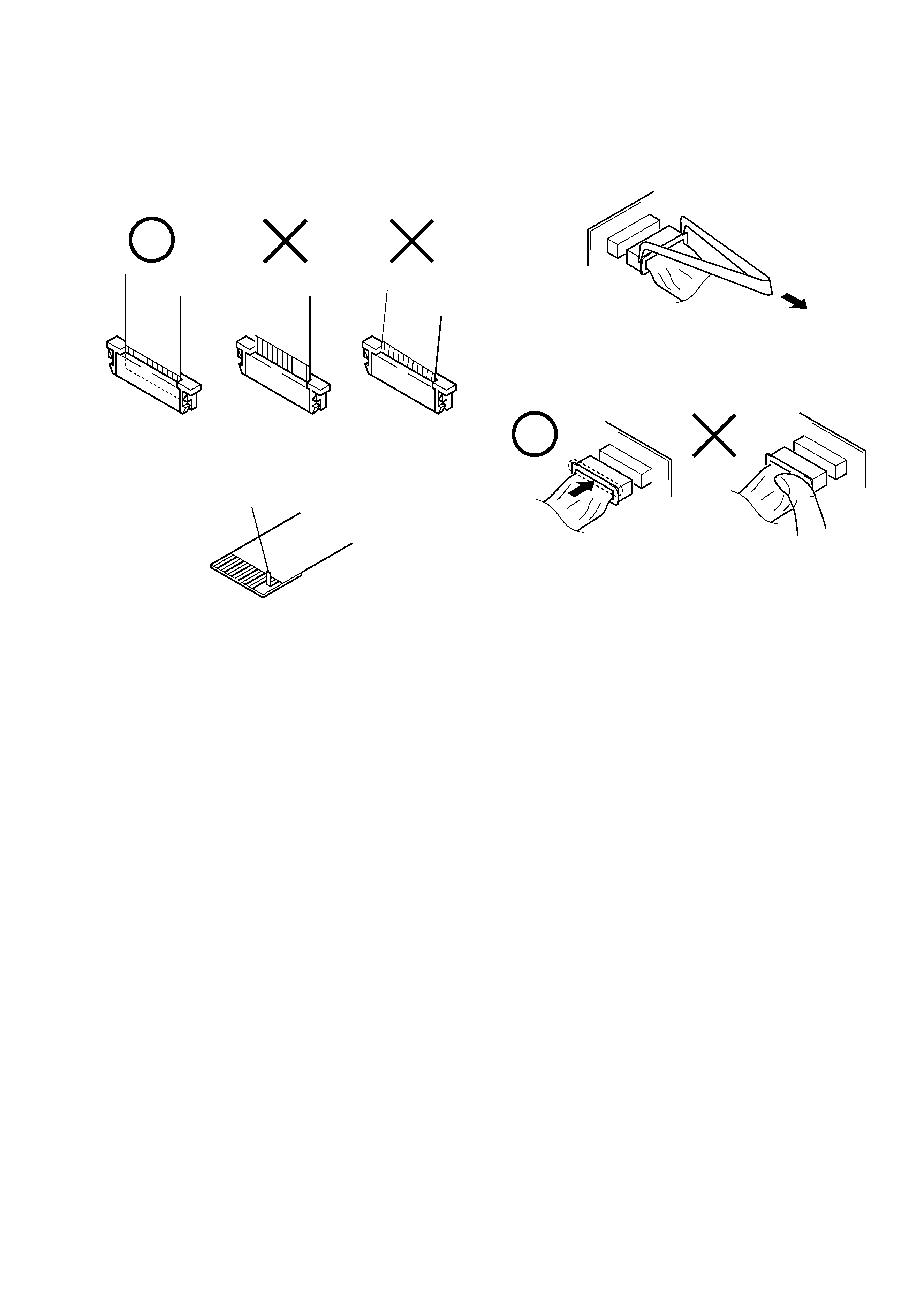
1.
NOTE FOR REPAIR
Make sure that the flat cable and flexible board are not cracked of
bent at the terminal.
Do not insert the cable insufficiently nor crookedly.
When remove a connector, don't pull at wire of connector.
It is possible that a wire is snapped.
Cut and remove the part of gilt
which comes off at the point.
(Be careful or some pieces of
gilt may be left inside)
When installing a connector, don't press down at wire of connector.
It is possible that a wire is snapped.
SERVICE NOTE