SERVICE MANUAL
Sony Corporation
Personal Audio Group
Published by Sony Engineering Corporation
US Model
Canadian Model
AEP Model
UK Model
E Model
Australian Model
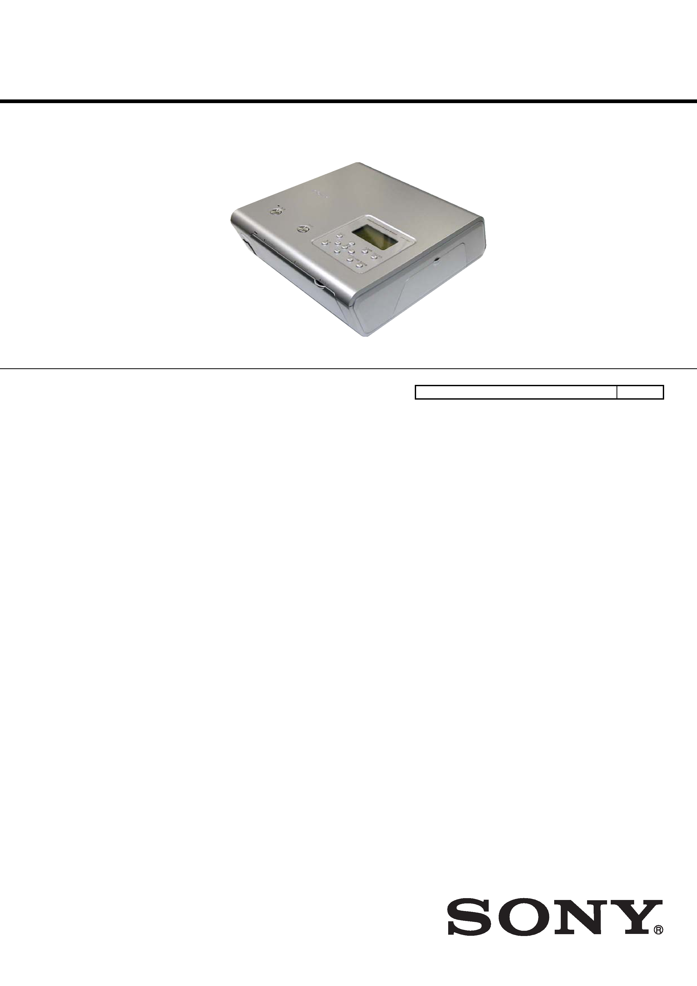
DIGITAL PHOTO PRINTER
9-879-657-01
2005E22-1
© 2005.5
Ver. 1.0 2005.05
SPECIFICATIONS
DPP-FP50
Printing method
Dye sublimation printing (Yellow/Magenta/Cyan 3 pass)
Resolution
300 (H) x 300 (V) dpi
Image processing per dot
256 levels (8 bits for each Yellow/Magenta/Cyan),
approx. 16 770 000 colors
Printing size
Post Card (4 x 6 inch) size:
101.6 x 152.4 mm (maximum, borderless)
3.5 x 5 inch size:
89 x 127 mm (maximum, borderless)
Printing time (per sheet)
Post Card (4 x 6 inch) size: approx. 67 seconds
3.5 x 5 inch size:
approx. 57 seconds
(When printing from a memory card inserted in the printer's slot,
excluding the time for data processing and transferring)
Input/Output connectors
USB connector (1)
PictBridge/CAMERA connector (1)
VIDEO OUT (output) connector (Phono jack x 1)
1 Vp-p, 75 ohms (unbalanced), sync negative
Slot
"Memory Stick" insertion slot (1)
CompactFlash card inseation slot (1)
SD Card insertion slot (1)
Compatible image file formats*1
JPEG:
DCF*2 2.0 compatible, Exif*3 2.21 compatible, JFIF
(Baseline JPEG with 4:4:4, 4:2:2, or 4:2:0 format)
TIFF:
Exif 2.2 compatible (TIFF-RGB, non-compressed)
BMP:
24bit Windows format
Maximum number of pixels to be handled
6 400 (H) x 4 800 (V) dots
(Excluing Index Print and part of Creative Print)
Maximum number of files to be handled
9 999 files for a memory card/an external device
Print cartridge/Print Paper
See "Preparing the printing pack (not supplied)" on page 5.
Power requirements
DC IN jack, DC24V
(On standby mode, less than 1W)
Operating temperature
5 °C to 35 °C (41 °F to 95 °F)
Dimensions
Approx. 182 x 66 x 210 mm
(71/
4 x 2
5/
8 x 8
3/
8 inches)
(w/h/d, excluding protruding parts)
(360 mm (141/
4 inches) of depth when the paper tray is installed.)
Mass
Approx. 1,200 kg (2 lb 10 oz)
(excluding the 165 kg (6 oz) paper tray)
Supplied accessories
See "Checking the contents of the package" on page 4.
Design and specifications are subject to change without notice.
*1: Some special file types are not compatible.
*2: "DCF" stands for Design rule for Camera File system.
*3: "Exif" is an image file format containing an image data added with
its thumbnail data for viewing, shot date data and the shooting
conditions data.
Model Name Using Similar Mechanism
NEW
2
DPP-FP50
Notes on chip component replacement
· Never reuse a disconnected chip component.
· Notice that the minus side of a tantalum capacitor may be
damaged by heat.
Flexible Circuit Board Repairing
· Keep the temperature of the soldering iron around 270 °C
during repairing.
· Do not touch the soldering iron on the same conductor of the
circuit board (within 3 times).
· Be careful not to apply force on the conductor when soldering
or unsoldering.
UNLEADED SOLDER
Boards requiring use of unleaded solder are printed with the lead-
free mark (LF) indicating the solder contains no lead.
(Caution: Some printed circuit boards may not come printed with
the lead free mark due to their particular size)
: LEAD FREE MARK
Unleaded solder has the following characteristics.
· Unleaded solder melts at a temperature about 40 °C higher
than ordinary solder.
Ordinary soldering irons can be used but the iron tip has to be
applied to the solder joint for a slightly longer time.
Soldering irons using a temperature regulator should be set to
about 350 °C.
Caution: The printed pattern (copper foil) may peel away if
the heated tip is applied for too long, so be careful!
· Strong viscosity
Unleaded solder is more viscous (sticky, less prone to flow)
than ordinary solder so use caution not to let solder bridges
occur such as on IC pins, etc.
· Usable with ordinary solder
It is best to use only unleaded solder but unleaded solder may
also be added to ordinary solder.
SAFETY CHECK-OUT
After correcting the original service problem, perform the follow-
ing safety check before releasing the set to the customer:
Check the antenna terminals, metal trim, "metallized" knobs,
screws, and all other exposed metal parts for AC leakage.
Check leakage as described below.
LEAKAGE TEST
The AC leakage from any exposed metal part to earth ground and
from all exposed metal parts to any exposed metal part having a
return to chassis, must not exceed 0.5 mA (500 microamperes.).
Leakage current can be measured by any one of three methods.
1. A commercial leakage tester, such as the Simpson 229 or RCA
WT-540A. Follow the manufacturers' instructions to use these
instruments.
2. A battery-operated AC milliammeter. The Data Precision 245
digital multimeter is suitable for this job.
3. Measuring the voltage drop across a resistor by means of a
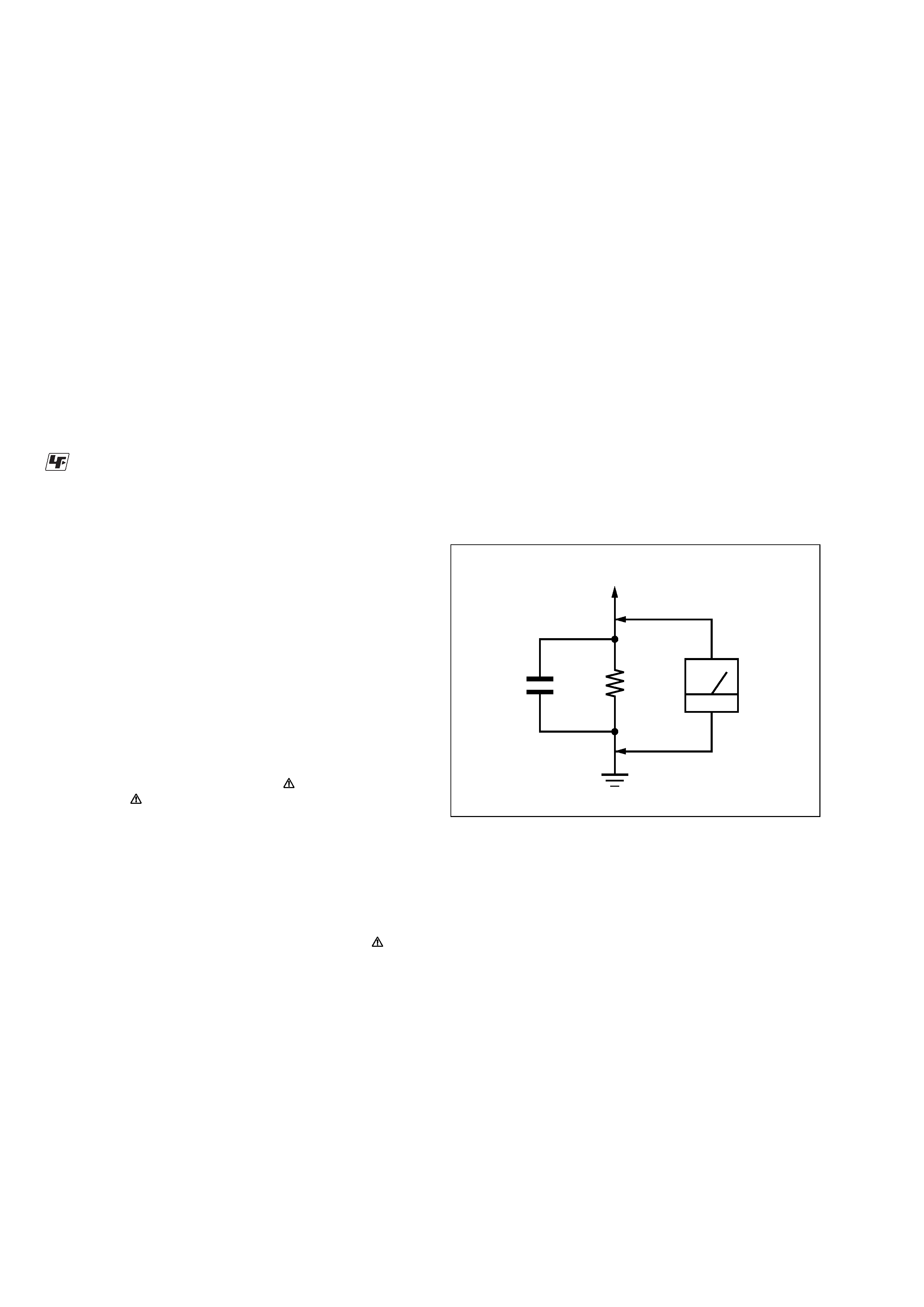
VOM or battery-operated AC voltmeter. The "limit" indica-
tion is 0.75 V, so analog meters must have an accurate low-
voltage scale. The Simpson 250 and Sanwa SH-63Trd are ex-
amples of a passive VOM that is suitable. Nearly all battery
operated digital multimeters that have a 2 V AC range are suit-
able. (See Fig. A)
Fig. A.
Using an AC voltmeter to check AC leakage.
1.5 k
0.15
µF
AC
voltmeter
(0.75 V)
To Exposed Metal
Parts on Set
Earth Ground
SAFETY-RELATED COMPONENT WARNING!!
COMPONENTS IDENTIFIED BY MARK
OR DOTTED LINE
WITH MARK
ON THE SCHEMATIC DIAGRAMS AND IN
THE PARTS LIST ARE CRITICAL TO SAFE OPERATION.
REPLACE THESE COMPONENTS WITH SONY PARTS WHOSE
PART NUMBERS APPEAR AS SHOWN IN THIS MANUAL OR
IN SUPPLEMENTS PUBLISHED BY SONY.
ATTENTION AU COMPOSANT AYANT RAPPORT
À LA SÉCURITÉ!
LES COMPOSANTS IDENTIFIÉS PAR UNE MARQUE
SUR
LES DIAGRAMMES SCHÉMATIQUES ET LA LISTE DES
PIÈCES
SONT
CRITIQUES
POUR
LA
SÉCURITÉ
DE
FONCTIONNEMENT. NE REMPLACER CES COM- POSANTS
QUE PAR DES PIÈCES SONY DONT LES NUMÉROS SONT
DONNÉS DANS CE MANUEL OU DANS LES SUPPLÉMENTS
PUBLIÉS PAR SONY.

3
DPP-FP50
1.
SERVICING NOTES
2.
SERVICE MODE
2-1.
STARTUP PROCEDURE ............................................... 7
2-2.
DENSITY ADJUSTMENT PROCEDURE WHEN
REPLACING THERMAL PRINTER OR
MAIN BOARD ............................................................... 7
2-3.
VIDEO OUTPUT AND LCD CHECK ........................... 8
2-4.
BUTTON/FAN/LED OPERATION CHECK ................. 9
2-5.
USB HOST/DEVICE COMMUNICATION CHECK .... 10
2-6.
MECHANICAL OPERATION CHECK ......................... 10
2-7.
ABOUT THE ERROR INDICATION ............................ 11
3.
VERSION UPGRADE
4.
TROUBLESHOOTING
4-1.
ELECTRICAL TROUBLESHOOTING ......................... 14
4-2.
MECHANICAL TROUBLESHOOTING ....................... 15
5.
DIAGRAMS
5-1.
BLOCK DIAGRAM Overall ................................... 17
5-2.
SCHEMATIC DIAGRAM MAIN Board (1/3) ....... 19
5-3.
SCHEMATIC DIAGRAM MAIN Board (2/3) ....... 20
5-4.
SCHEMATIC DIAGRAM MAIN Board (3/3) ....... 21
5-5.
PRINTED WIRING BOARD
MAIN Board (Component Side) ............................... 22
5-6.
PRINTED WIRING BOARD
MAIN Board (Conductor Side) ................................. 23
5-7.
SCHEMATIC DIAGRAM BGA Board (1/2) ......... 24
5-8.
SCHEMATIC DIAGRAM BGA Board (2/2) ......... 25
5-9.
PRINTED WIRING BOARD
BGA Board (Component Side) ................................. 26
5-10. PRINTED WIRING BOARD
BGA Board (Conductor Side) ................................... 27
5-11. SCHEMATIC DIAGRAM MSSD Board ................ 28
5-12. PRINTED WIRING BOARD
MSSD Board (Component Side) ............................... 29
5-13. PRINTED WIRING BOARD
MSSD Board (Conductor Side) ................................. 29
5-14. SCHEMATIC DIAGRAM SW Board ..................... 30
5-15. PRINTED WIRING BOARD
SW Board (Component Side) .................................... 31
5-16. PRINTED WIRING BOARD
SW Board (Conductor Side) ...................................... 31
5-17. SCHEMATIC DIAGRAM USBA Board ................ 32
5-18. PRINTED WIRING BOARD
USBA Board (Component Side) ............................... 33
5-19. PRINTED WIRING BOARD
USBA Board (Conductor Side) ................................. 33
6.
EXPLODED VIEWS
6-1.
Case (Upper)/Rear Panel Block ...................................... 35
6-2.
Chassis Block .................................................................. 36
7.
ELECTRICAL PARTS LIST
TABLE OF CONTENTS
4
DPP-FP50
1
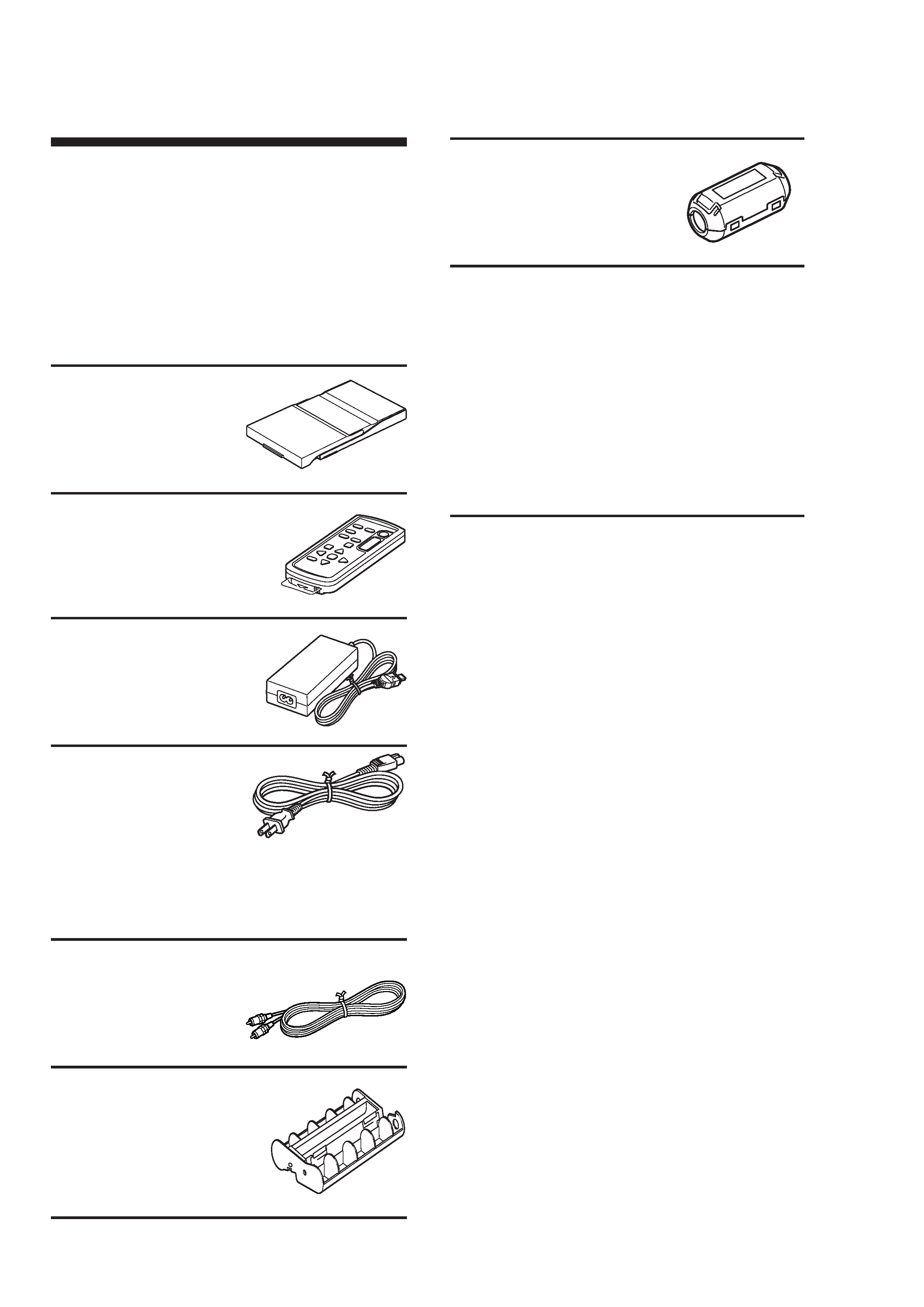
Checking the
contents of the
package
Make sure that the following accessories
are supplied with your printer.
Paper tray (1)
Remote commander (1)
The button-type lithium
battery has been already
installed in the commander.
AC adapter AC-S24V1 (1)
AC power cord * (1)
* The AC power cord illustrated is for 120V
only. The plug shape and specifications of
the AC power cord differ depending on the
region you purchased the printer.
Video connecting cable (1)
Cleaning cartridge (1)
Clamp filter (1)
CD-ROM (1)
Sony DPP-FP50 Printer Driver
Software for Windows® XP
Professional/Windows® XP Home
Edition/Windows® XP Media
Center Edition/Windows® 2000
Professional/Windows® Millennium
Edition/Windows® 98 Second
Edition
PictureGear Studio Ver.2.0
· Sample color printing pack (1)
· Operating Instructions (this booklet, 1)
· Quick Start Guide (1)
· Warranty (1)
· Sony End User Software License
Agreement (1)

5
DPP-FP50
2
Preparing the
printing pack
To print an image, you need a
printing pack designed for the
printer. The sample color
printing pack contains a set of
10 sheets of Post card size print
paper and a print cartridge for
10 prints.
Sizes of print paper
You can use the print paper from the
following two sizes:
· Post card (4 x 6 inch) size (101.6 x 152.4
mm)*
· 3.5 x 5 inch size (89 x 127 mm)*
(*the maximum borderless printing size)
Optional printing packs
You can use the following optional
printing packs for the printer:
Post card size
SVM-F40P
·Two packs with each 20 sheets of Post
Card size photo paper
· Print cartridge for 40 prints
SVM-F80P
· Four packs with each 20 sheets of Post
Card size photo paper
·2 Print cartridges each for 40 prints
3.5 x 5 inch sizebSVM-F40L*
·Two packs with each 20 sheets of 3.5 x
5 inch size photo paper
· Print cartridge for 40 prints
*Note
In some regions, 3.5 x 5 inch size print paper
is not sold.
To order printing packs, visit the
following web site:
www.sony.com/printers
Notes on using printing packs
· Always use the print cartridge and print
paper from the same carton as a set. If you
mix cartridges and paper of different types,
printing may not be possible.
· The side without the imprinting is the
printing surface. Inferior print quality may
result if the printing surface is contaminated
with dust or fingerprints. Be careful to avoid
touching the printing surface.
· Do not bend the paper or tear it off at the
perforations before printing.
· Do not print on used sheets of print paper
or attempt to rewind the ribbon inside the
print cartridge. Doing so could result in
damages to the printer.
· Please do not disassemble the print cartridge.
· Do not pull out the ribbon from the print
cartridge.
Notes on storing printing packs (for
quality prints)
· When you are going to store a partially-used
pack of the print cartridge and print paper for
an extended period of time, store it in its
original bag or in a similar container.
· Avoid placing the printing pack in locations
that are subject to high temperature, high
humidity, excessive dust, or direct sunlight.
· Use printing pack within two years from the
date of production.
Note on storing printouts
· Do not affix cellophane tape or plastic erasers
to printouts. Also avoid leaving printouts
under plastic desk mats.
Caution
· TV program, films, video tapes and other
materials may be copyrighted. Unauthorized
video printing of such materials may be
country to the provisions of the copyright
law.