
Mini Hi-Fi
Component
System
3-861-229-13(1)
©1997 by Sony Corporation
DHC-MD515
Operating Instructions
Owner's Record
The model and serial numbers are located on the rear panel of the unit. Record the
serial number in the space provided below. Refer to them whenever you call upon
your Sony dealer regarding this product.
Model No.
Serial No.
2
WARNING
To prevent fire or shock hazard, do not
expose the unit to rain or moisture.
To avoid electrical shock, do not open the cabinet.
Refer servicing to qualified personnel only.
Do not install the appliance in a confined space,
such as a bookcase or built-in cabinet.
US and foreign patents licensed from Dolby
Laboratories Licensing Corporation.
The laser component in this product is capable of
emitting radiation exceeding the limit for Class 1.
This caution label is located inside the unit.
This appliance is classified
as a CLASS 1 LASER
product. The CLASS 1
LASER PRODUCT
MARKING is located on
the rear exterior.
INFORMATION
This equipment has been tested and found to
comply with the limits for a Class B digital device,
pursuant to Part 15 of the FCC Rules. These limits
are designed to provide reasonable protection
against harmful interference in a residential
installation. This equipment generates, uses, and can
radiate radio frequency energy and, if not installed
and used in accordance with the instructions, may
cause harmful interference to radio
communications. However, there is no guarantee
that interference will not occur in a particular
installation. If this equipment does cause harmful
interference to radio or television reception, which
can be determined by turning the equipment off and
on, the user is encouraged to try to correct the
interference by one or more of the following
measures:
Reorient or relocate the receiving antenna.
Increase the separation between the equipment
and receiver.
Connect the equipment into an outlet on a circuit
different from that to which the receiver is
connected.
Consult the dealer or an experienced radio/TV
technician for help.
CAUTION
You are cautioned that any changes or modifications
not expressly approved in this manual could void
your authority to operate this equipment.
Note on CATV system installer:
This reminder is provided to call CATV system
installer's attention to Article 82040 of the NEC that
provides guidelines for proper grounding and, in
particular, specifies that the cable ground shall be
connected to the grounding system of the building,
as close to the point of cable entry as practical.
NOTICE FOR THE CUSTOMERS IN
CANADA
CAUTION:
TO PREVENT ELECTRIC SHOCK, DO NOT USE
THIS POLARIZED AC PLUG WITH AN
EXTENSION CORD,
RECEPTACLE OR OTHER OUTLET UNLESS THE
BLADES CAN BE FULLY INSERTED TO PREVENT
BLADE EXPOSURE.
NOTICE FOR THE CUSTOMERS IN THE
U.S.A.
CAUTION
The use of optical instruments with this product will
increase eye hazard.
This symbol is intended to alert the
user to the presence of important
operating and maintenance (servicing)
instructions in the literature
accompanying the appliance.
This symbol is intended to alert the
user to the presence of uninsulated
"dangerous voltage" within the
product's enclosure that may be of
sufficient magnitude to constitute a
risk of electric shock to persons.

3
Table of Contents
Getting Started
Step 1: Hooking up the system ............ 4
Step 2: Setting the time ......................... 5
Step 3: Presetting radio stations .......... 6
Step 4: Using the detachable
controller ........................................... 8
Connecting optional A/V components
and outdoor antennas ................... 10
Basic Operations
Playing a CD ......................................... 12
Recording a whole CD on an MD ...... 13
Playing an MD ...................................... 15
Listening to the radio ........................... 17
Recording from the radio .................... 18
The CD Player
Playing CD tracks repeatedly ............. 20
Playing CD tracks in random
order ................................................ 20
Programming CD tracks ..................... 21
Using the CD display ........................... 23
Looping part of a CD track ................. 24
Labeling a CD ....................................... 25
Checking the CD-TEXT information . 27
The MD Deck Playing
Playing MD tracks repeatedly ............ 29
Playing MD tracks
in random order ............................. 29
Programming MD tracks .................... 30
Using the MD display .......................... 32
The MD Deck Recording
Before you start recording .................. 33
Recording methods on this system .... 34
Recording multiple CDs on multiple
MDs ................................................. 35
Recording multiple CDs on MDs in
sequence .......................................... 36
Recording your favorite CD tracks on
MDs ................................................. 37
Recording only the first track on each
CD .................................................... 39
Recording the current CD track ......... 40
Recording on an MD manually .......... 41
Starting recording with 6 seconds of
prestored audio data ..................... 42
Marking track numbers ....................... 43
Making a space between tracks 3
seconds long ................................... 44
The MD Deck Editing
Before you start editing ....................... 45
Labeling an MD .................................... 46
Erasing recordings ............................... 47
Moving recorded tracks ...................... 49
Dividing recorded tracks .................... 50
Combining recorded tracks ................ 51
Undoing the last edit ........................... 53
Sound Adjustment
Adjusting the sound ............................ 54
Selecting the Preset Equalizer menu . 54
Other Features
Labeling the preset stations ................ 55
Using the Radio Data System (RDS) . 56
Falling asleep to music ........................ 58
Waking up to music ............................. 59
Timer recording radio programs ....... 60
Additional Information
Precautions ............................................ 63
Using the Self-Diagnostic Display ..... 64
System limitations of MDs .................. 65
Troubleshooting ................................... 65
Specifications ........................................ 69
Index ....................................................... 71
4
+
_
+
_
L
R
Getting Started
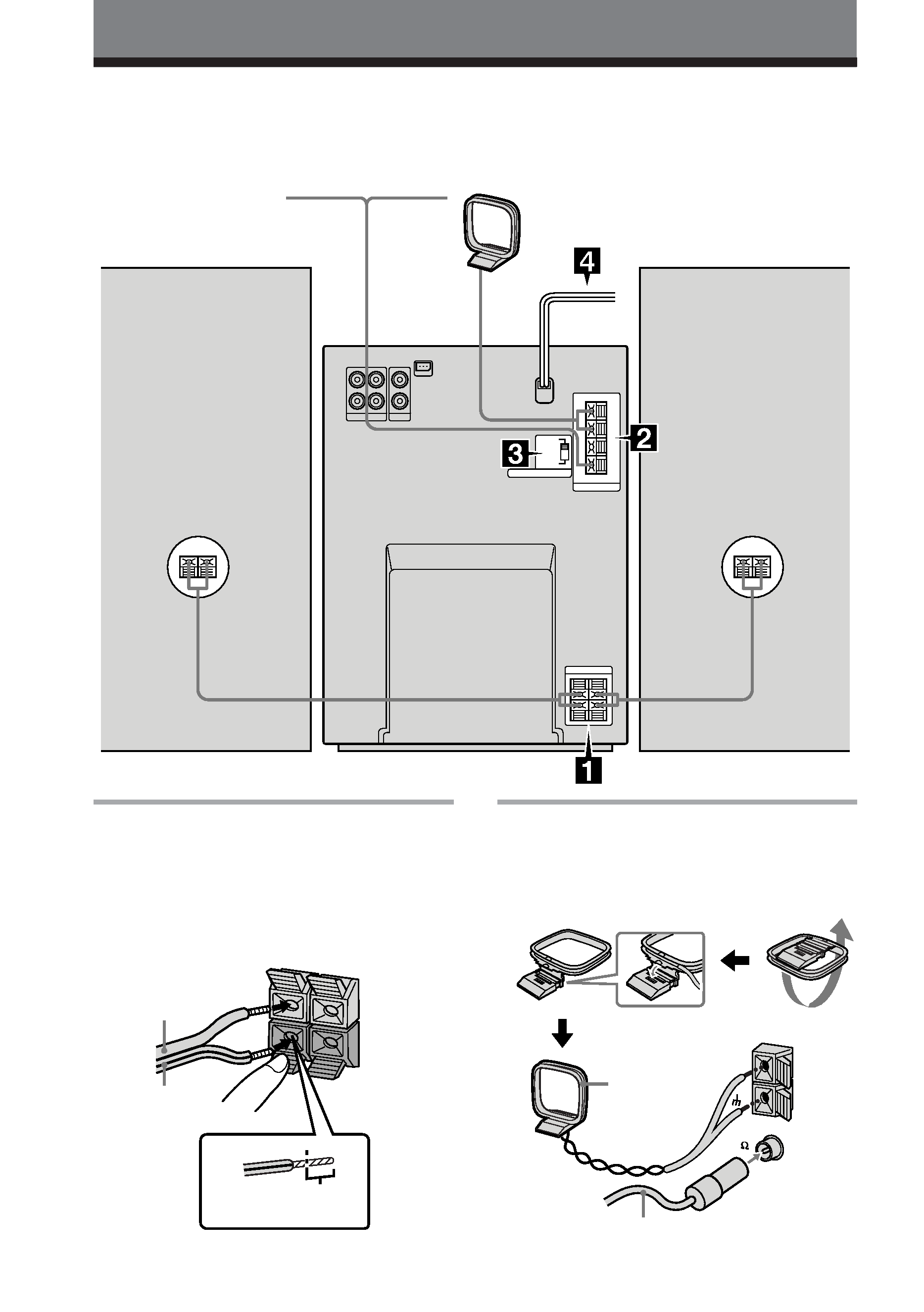
Step 1: Hooking up the system
Follow steps 1 and 2 to hook up your system using the supplied cords and accessories. Follow
steps 3 and 4 to complete the hook up procedure.
Left speaker
Right speaker
DHC-MD515
rear panel
FM antenna
AM loop antenna
Connect the speakers.
Connect the speaker cords to SPEAKER
terminals of the same color.
Keep the speaker cords away from the
antennas to prevent noise.
1
Solid (`)
Stripe (')
Connect the FM/AM antennas.
Set up the AM loop antenna, then
connect it.
European model
2
AM loop
antenna
Extend the FM lead
antenna
horizontally.
Insert this portion.
FM 75
COAXIAL
AM
5
Other models
Set VOLTAGE SELECTOR to the
position of your local power line
voltage (except for North American
and European model).
Connect the AC power cord to a
wall outlet.
If the plug of the AC power cord does
not fit your wall outlet, detach the
supplied adapter from the plug (except
for North American and European
model).
Before you turn on the system
Remove the transport MD cartridge from the
slot. If you turn on the system before
removing the cartridge, "MD MECHA
ERROR" appears. Turn off the system, then
remove the cartridge after the clock display
appears (see page 63).
3
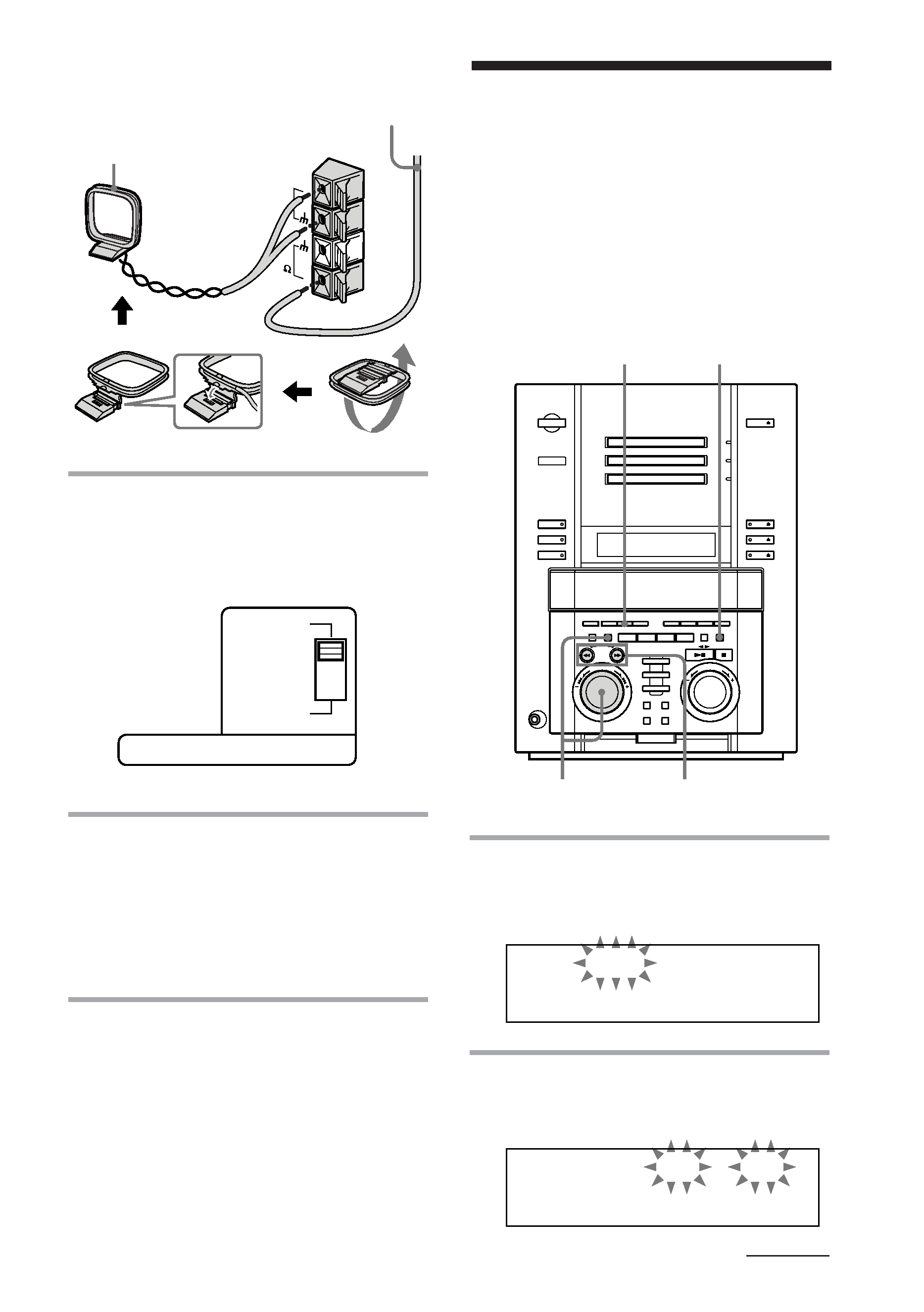
4
Step 2: Setting the
time
You must set the time before you can use the
timer functions. The clock is on a 24-hour
system for the European model, and a 12-
hour system for other models. The 12-hour
system is used for illustration purpose. You
can set the time while the power is off.
1 Press CLOCK/TIMER SET.
The day of the week indication ("SUN")
flashes.
2 Turn MULTI JOG to set the day of
the week, then press ENTER/YES.
The hour indication flashes.
1
2,3,4
DISPLAY
CURSOR N/n
continued
TAPE
110 120V
220 240V
VOLTAGE SELECTOR
AM loop antenna
Extend the FM lead
antenna
horizontally.
FM
75
AM
SU
2
1: 0AM
0
N
MO
2
1: 0AM
0
N