D-FJ75TR
US Model
AEP Model
UK Model
E Model
SERVICE MANUAL
FM/AM PORTABLE CD PLAYER
Model Name Using Similar Mechanism
D-E770/EJ711/EJ715
CD Mechanism Type
CDM-3123EBA
Optical Pick-up Name
DAX-23E
SPECIFICATIONS
CD player
System
Compact disc digital audio system
Laser diode properties
Material: GaAlAs
Wavelength:
= 780 nm
Emission duration: Continuous
Laser output: Less than 44.6
µW
(This output is the value measured at a distance
of 200 mm from the objective lens surface on
the optical pick-up block with 7 mm aperture.)
D-A conversion
1-bit quartz time-axis control
Frequency response
20 - 20 000 Hz
+1
2 dB (measured by EIAJ CP-307)
Output (at 4.5 V input level)
Line output (stereo minijack)
Output level 0.7 V rms at 47 k
Recommended load impedance over 10 k
Headphones (stereo minijack)
Approx.5 mW + Approx. 5 mW at 16
(Approx. 1 mW + Approx. 1 mW at 16
)*
*For the customers in France
Optical digital output (optical output connector)
Output level: 21 - 15 dBm
Wavelength: 630 - 690 nm at peak level
Radio (LCD remote control
with built in digital tuner)
Frequency range (STEP)
Tuner type "U"
FM: 87.5 - 108.0 MHz (100 kHz STEP)
AM: 530 - 1 710 kHz (10 kHz STEP)
Tuner type "E"
FM: 87.5 - 108.0 MHz (50 kHz STEP)
AM: 531 - 1 602 kHz (9 kHz STEP)
Tuner type "J"
FM: 76 - 90 MHz (100 kHz STEP)
AM: 531 - 1 710 kHz (9 kHz STEP)
Antenna
FM: Headphones/earphones cord antenna
AM: Built-in ferrite bar antenna
General
Power requirements
For the area code of the model you
purchased, check the upper left side of the
bar code on the package.
·Two Sony NC-WMAA rechargeable
batteries: 2.4 V DC
· Sony NH-WM2AA rechargeable batteries:
2.4 V DC
·Two LR6 (size AA) batteries: 3 V DC
·AC power adaptor (DC IN 4.5 V jack):
US model: 120 V, 60 Hz
AEP, E13, EE, FR model:
220 - 230 V, 50/60 Hz
UK model : 230 - 240V, 50 Hz
E33 model : 100 - 240V, 50/60 Hz
,
HK model : 220V, 50/60 Hz
CH model : 220V, 50 Hz
· Sony DCC-E345 car battery cord for use on
car battery: 4.5 V DC
Battery life* (approx. hours)
(When you use the CD player on a flat and stable
surface.)
Playing time varies depending on how the CD
player is used.
When using
G-PROTECTION
RADIO
on
off
on
Two NC-WMAA
8
7
14
(charged for
about 3 hours**)
NH-WM2AA
18
15
30
(charged for
about 4 hours**)
Two Sony alkaline 32
28
50
batteries LR6SG
* Measured value by the standard of EIAJ
(Electronic Industries Association of Japan).
** Charging time varies depending on how the
rechargeable battery is used.
Operating temperature
5
°C - 35°C (41°F - 95°F)
Dimensions (w/h/d) (excluding
projecting parts and controls)
Approx. 131.6
× 25.0 × 141.4 mm
(5 1/4
× 1 × 5 5/8 in.)
Mass (excluding accessories)
Approx. 185 g (6.6 oz.)
· Abbreviation
CH : Chinese model
EE : East European model
FR : French model
HK : Hong Kong model
E13 : AC220-230V area model
E33 : AC100-240V area model
-- Continued on next page --
Sony Corporation
Personal Audio Company
Published by Sony Engineering Corporation
9-927-922-13
2002F1600-1
© 2002.06
Ver 1.2 2002. 06

-- 2 --
TABLE OF CONTENTS
SAFETY-RELATED COMPONENT WARNING!!
COMPONENTS IDENTIFIED BY MARK 0 OR DOTTED LINE WITH
MARK 0 ON THE SCHEMATIC DIAGRAMS AND IN THE PARTS
LIST ARE CRITICAL TO SAFE OPERATION. REPLACE THESE
COMPONENTS WITH SONY PARTS WHOSE PART NUMBERS
APPEAR AS SHOWN IN THIS MANUAL OR IN SUPPLEMENTS
PUBLISHED BY SONY.
CAUTION
Use of controls or adjustments or performance of procedures
other than those specified herein may result in hazardous radiation
exposure.
Flexible Circuit Board Repairing
· Keep the temperature of the soldering iron around 270 °C dur-
ing repairing.
· Do not touch the soldering iron on the same conductor of the
circuit board. (within 3 times)
· Be careful not to apply force on the conductor when soldering
or unsoldering.
Notes on chip component replacement
· Never reuse a disconnected chip component.
· Notice that the minus side of a tantalum capacitor may be dam-
aged by heat.
1.
SERVICING NOTES ····················································· 3
2.
GENERAL ······································································· 4
3.
DISASSEMBLY ······························································ 5
3-1. Cabinet (Upper) ··································································· 5
3-2. CDM-3123EBA and Main Board ········································ 5
4.
ELECTRICAL ADJUSTMENTS ······························· 6
5.
DIAGRAMS ····································································· 7
5-1. IC Pin Function Description ················································ 7
5-2. IC Block Diagrams ······························································ 9
5-3. Block Diagram ··································································· 10
5-4. Printed Wiring Board ························································· 12
5-5. Schematic Diagram ···························································· 15
6.
EXPLODED VIEWS ···················································· 18
6-1. Cabinet Section ·································································· 18
6-2. Main Section ······································································ 19
6-3. Mechanism Section (CDM-3123EBA) ······························ 20
7.
ELECTRICAL PARTS LIST ···································· 21
Accessories
Supplied accessories
For the area code of the location in which you
purchased the CD player, check the upper left side
of the bar code on the package.
AC power adaptor (1)
Headphones with LCD remote control with built
in digital tuner (1)
Rechargeable batteries (2)
Battery carrying case (1)
Carrying case (1)
For US customers
The AC power adaptor supplied is not intended to
be serviced. Should the AC power adaptor cease to
function in its intended manner, during the warranty
period, the adaptor should be returned to your
nearest Sony Service Center or Sony Authorized
Repair Center for replacement, or after warranty
period, it should be discarded.
Design and specifications are subject to change
without notice.
-- 3 --
The laser diode in the optical pick-up block may suffer electro-
static breakdown because of the potential difference generated by
the charged electrostatic load, etc. on clothing and the human body.
During repair, pay attention to electrostatic breakdown and also
use the procedure in the printed matter which is included in the
repair parts.
The flexible board is easily damaged and should be handled with
care.
Befor Replacing the Optical Pick-Up Block
Please be sure to check thoroughly the parameters as par the "Op-
tical Pick-Up Block Checking Procedures" (Part No.: 9-960-027-
11) issued separately before replacing the optical pick-up block.
Note and specifications required to check are given below.
· FOK output: IC601 eg pin
When checking FOK, remove the lead wire to disc motor.
· RF signal P-to-P value: 0.35 to 0.65 Vp-p
Precautions for Checking Emission of Laser Diode
Laser light of the equipment is focused by the object lens in the
optical pick-up so that the light focuses on the reflection surface
of the disc. Therefore, be sure to keep your eyes more then 30 cm
apart from the object lens when you check the emission of laser
diode.
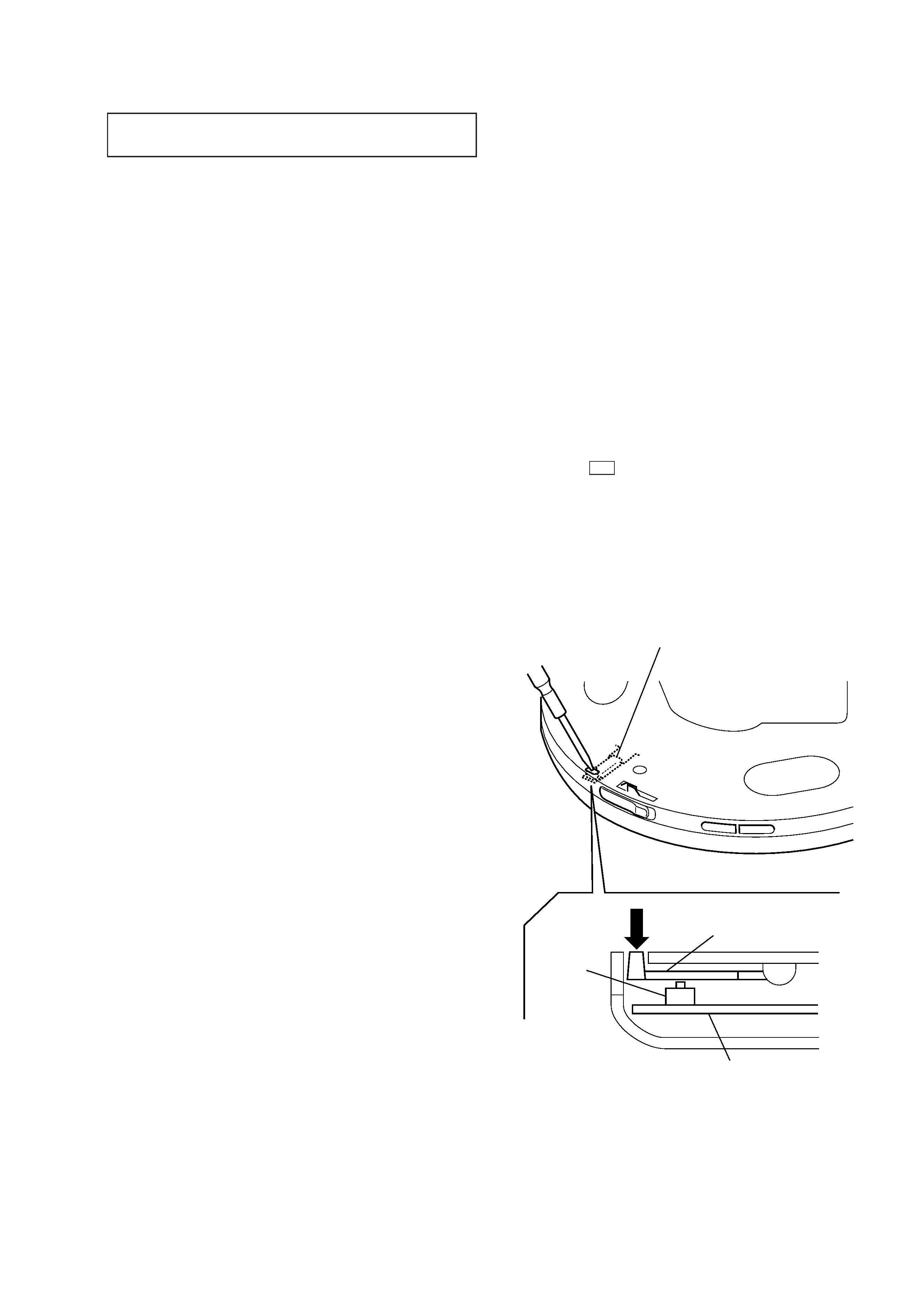
Laser Diode Checking Methods
During normal operation of the equipment, emission of the laser
diode is prohibited unless the upper lid is closed while turning ON
the S801. (push switch type)
The following two checking methods for the laser diode are oper-
able.
· Method:
Emission of the laser diode is visually checked.
1. Open the upper lid.
2. With a disc not set, turn on the S801 with a screwdriver having
a thin tip as shown in Fig.1.
Note: Do not push the detection lever strongly, or it may be bent or dam-
aged.
3. Press the u button.
4. Observing the objective lens, check that the laser diode emits
light.
When the laser diode does not emit light, automatic power
control circuit or optical pickup is faulty.
In this operation, the objective lens will move up and down 5
times along with inward motion for the focus search.
NOTES ON HANDLING THE OPTICAL PICK-UP
BLOCK OR BASE UNIT
Fig. 1 Method to push the S801
detection lever
detection lever
S801
main board
SECTION 1
SERVICING NOTES
-- 4 --
SECTION 2
GENERAL
This section is extracted
from instruction manual.
Getting started
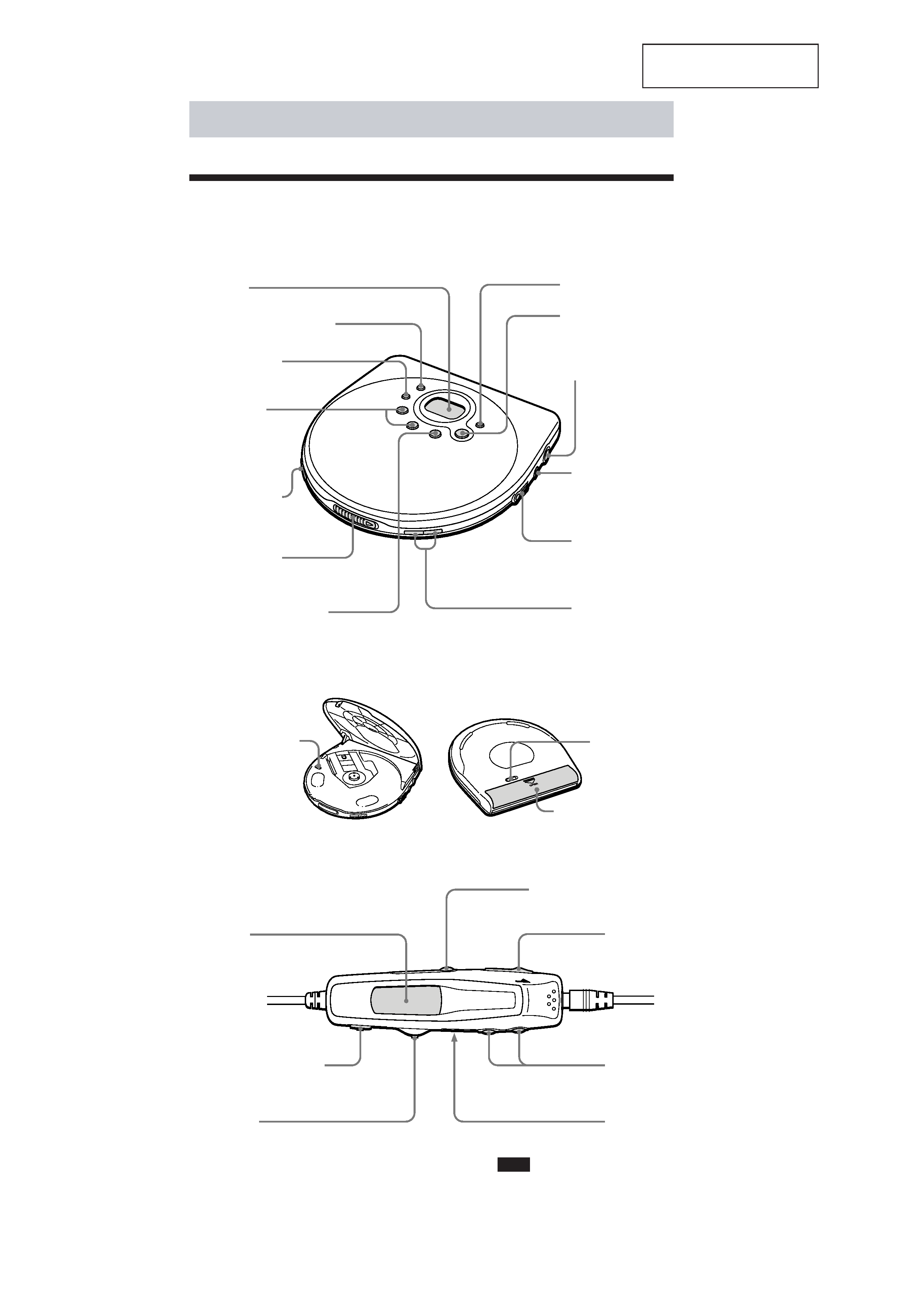
Locating the Controls
For details, see pages in parentheses.
CD player (front)
CD player (inside)
CD player (rear)
1 Display
(pages 8, 10, 11, 18, 19)
2 REPEAT/ENTER button
(pages 9 - 11)
3 PLAY MODE
button
(pages 9 - 11)
4
./>
(AMS/search)
buttons
(pages 7, 10, 11)
5 HOLD switch
(page 19)
6 OPEN switch
(page 6)
7
x (stop)/CHG (charge)
button
(pages 7, 20, 23)
qf G-PROTECTION
switch
(page 18)
qg AVLS switch
(page 19)
qh Battery compartment
(page 23)
8 SOUND button
(page 18)
9
u (play/pause)
button
(pages 7, 8, 11)
0 DC IN 4.5 V
(external power
input) jack
(pages 6, 23)
qa LINE OUT
(OPTICAL) jack
(page 21)
qs i/REMOTE jack
(page 6)
qd VOLUME +/
buttons
(page 7)
LCD remote control with builtin digital tuner
Note
Use only the supplied LCD remote
control with builtin digital tuner.You
cannot operate this CD player with the
remote control supplied with other CD
players.
qj Display
(pages 8, 12 - 17)
qk
x (stop)/RADIO OFF
button
(pages 7, 12, 17, 20)
w; RADIO ON/BAND·FM
MODE button (pages 12 - 17)
wa HOLD switch
(page 19)
ws VOL (volume)
+/ buttons
(page 7)
wd Clip (rear)
ql Jog lever
u ·MODE:
CD: play/pause (pages 7, 11)
Radio: selecting tuning mode (pages 14, 15)
./>·F /F+:
CD: AMS/search (pages 7, 10, 11)
Radio: tuning,selecting preset number
(pages 12, 15, 16)
Press or slide the lever to operate your CD player.
-- 5 --
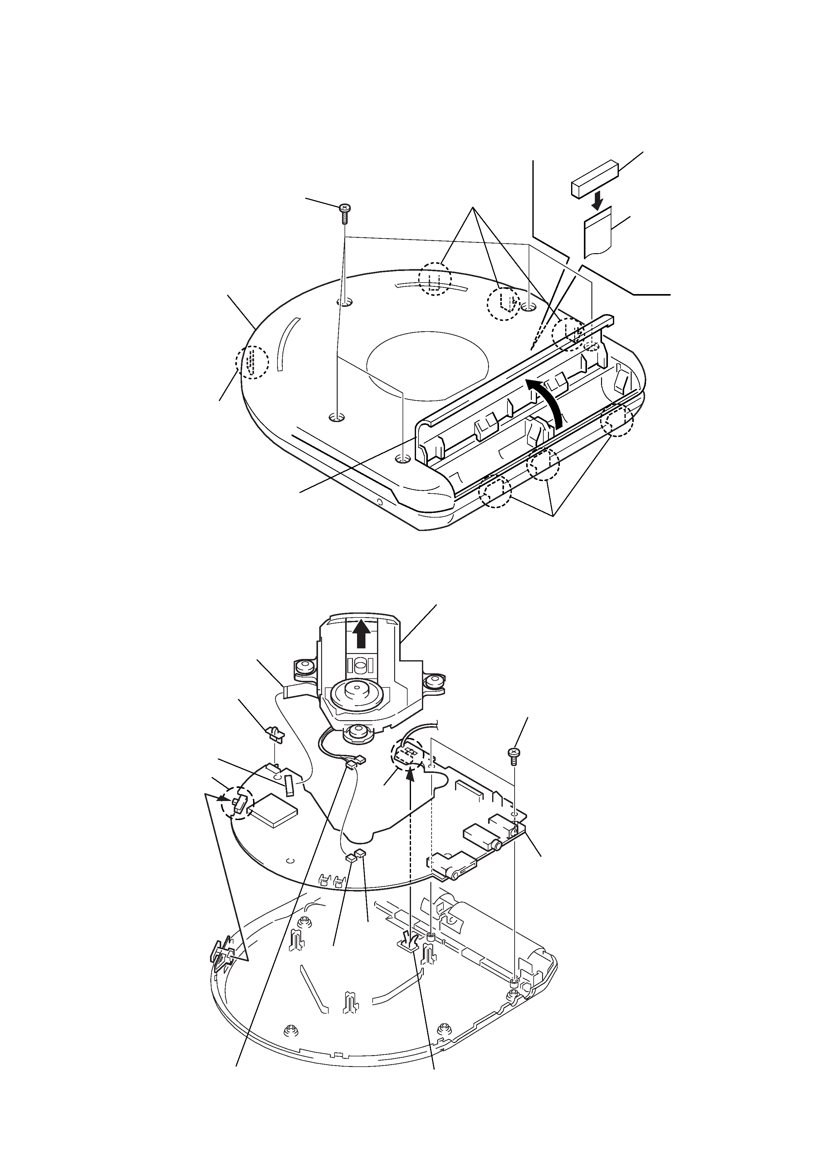
SECTION 3
DISASSEMBLY
3-1. CABINET (UPPER)
3-2. CDM-3123EBA AND MAIN BOARD
Note :
Follow the disassembly procedure in the numerical order given.
1
Five screws
(2
× 8)
2
Open the lid, battery case.
4
Flat cable
Three claws
Three claws
Claw
3
Cabinet (upper)
@
(There are 7 claws.)
Main board (CN801)
CN501
S803
CN502
CN503
S802
1
Flat cable
6
Main board
(Be careful that S802 and S803
engage with the knob when
they are re-assembled.)
2
Two connectors
3
CD mechanism
(CDM-3123EBA)
5
Two screws
4
Knob (JOG)
Knob (AVLS)