D-F180AN/F181/F400/F411/F415
SERVICE MANUAL
FM/AM COMPACT DISC COMPACT PLAYER
MICROFILM
Model Name Using Similar Mechanism
CD Mechanism Type
CDM-2811AAA
Optical Pick-up Name
DAX-01A
-- Continued on next page --
SPECIFICATIONS
US Model
D-F411/F415
Canadian Model
D-F181/F411
AEP Model
D-F180AN/F181/F411
UK Model
D-F181/F411
E Model
Australian Model
D-F181/F411/F415
Chinese Model
D-F411/F415
Tourist Model
D-F400
D-180AN/180ANC/181/
181C/181V/182CK/183
Radio section
Frequency range
· AEP, UK, French, Saudi Arabia model:
FM: 87.5 108.0MHz
AM: 531 1,602kHz
· Except AEP, UK, French, Saudi Arabia, Tourist
model:
(STEP switch)
9kHz step:
FM: 87.5 108.0MHz
AM: 531 1,710kHz
10kHz step:
FM: 87.5 108.0MHz
AM: 530 1,710kHz
· Tourist model:
(STEP switch)
9kHz step:
FM: 76.0 108.0MHz
AM: 531 1,710kHz
10kHz step:
FM: 87.5 108.0MHz
AM: 530 1,710kHz
Antenna
FM: Headphones/earphones cord antenna
AM: Built-in ferrite bar antenna
General
Power requirements
For the area code of the model you purchased,
check the
upper left side of the bar cord on the package.
· Sony BP-DM10 Rechargeable battery: 2.4V
DC, Ni-Cd, 650mAh
Sony BP-DM20 Rechargeable battery: 2.4V
DC, Ni-MH, 1,200mAh
· Two LR6 (size AA) batteries: 3V DC
· AC power adaptor (DC IN 4.5V jack):
US/Canadian/E92 model: 120V, 60Hz
AEP/E13/Argentine model:
220 230V, 50/60Hz
UK model: 230 240V, 50Hz
Saudi Arabia model: 110 240V, 50/60Hz
Australian model: 240V, 50Hz
Tourist, E33 model: 100 240V, 50/60Hz
Hong Kong model: 220V, 50/60Hz
Chinese model: 220V, 50Hz
· Sony CPM-300P mount plate for use on car
battery: 4.5V DC
Dimensions (w/h/d) (without projecting parts and
controls)
Approx. 133
× 33 × 152mm (51/4 × 15/16 × 6 in.)
Mass (without rechargeable battery)
Approx. 260g (9.2oz)
Operating temperature
5
°C 35°C (41°F 95°F)
Supplied accessories
For the area code of the model you purchased,
check the
upper left side of the bar cord on the package.
D-180AN
Earphones (1)
Connecting cord (Phono plug
× 2 stereo
miniplug) (1)
D-F181
AC power adaptor (1)
AC plug adaptor (1)*
Earphones (1)
Connecting cord (Phono plug
× 2 stereo
miniplug) (1)
* Supplied with E33, E13 and Saudi Arabia
models
Photo : D-F181
Ver 1.0 1998.06

-- 2 --
SAFETY-RELATED COMPONENT WARNING!!
COMPONENTS IDENTIFIED BY MARK ! OR DOTTED LINE WITH
MARK ! ON THE SCHEMATIC DIAGRAMS AND IN THE PARTS
LIST ARE CRITICAL TO SAFE OPERATION. REPLACE THESE
COMPONENTS WITH SONY PARTS WHOSE PART NUMBERS
APPEAR AS SHOWN IN THIS MANUAL OR IN SUPPLEMENTS
PUBLISHED BY SONY.
CAUTION
Use of controls or adjustments or performance of procedures
other than those specified herein may result in hazardous radiation
exposure.
Flexible Circuit Board Repairing
· Keep the temperature of the soldering iron around 270
°C during
repairing.
· Do not touch the soldering iron on the same conductor of the
circuit board (within 3 times).
· Be careful not to apply force on the conductor when soldering or
unsoldering.
Notes on chip component replacement
· Never reuse a disconnected chip component.
· Notice that the minus side of a tantalum capacitor may be damaged
by heat.
DANGER
Invisible laser radiation when open and interlock failed or defeated.
Avoid direct exposure to beam.
This Compact Disc player is
classified as a CLASS 1 LASER
product.
The CLASS 1 LASER
PRODUCT label is located on the
bottom exterior.
D-F400
AC power adaptor (1)
Earphones with remote control (1)
Rechargeable battery (1)
AC plug adaptor (1)
D-F411
AC power adaptor (1)
Headphones (1)*1
Earphones (1)*2
Connecting cord (Phono plug
× 2 stereo miniplug) (1)*3
AC plug adaptor (1)*
4
*1
Supplied with US model
*2
Not supplied with US model
*3
Not supplied with AEP, French and UK models
*
4
Supplied with E33, E13 and Saudi Arabia models
D-F415
AC power adaptor (1)
Headphones with remote control (1)*
1
Earphones with remote control (1)*2
Connecting cord (Phono plug
× 2 stereo miniplug) (1)*1
Rechargeable battery (1)
AC plug adaptor (1)*
3
*
1
Supplied with US model
*2
Not supplied with US model
*3
Not supplied with E13 model
Design and specifications are subject to change without notice.
ATTENTION AU COMPOSANT AYANT RAPPORT
À LA SÉCURITÉ!
LES COMPOSANTS IDENTIFÉS PAR UNE MARQUE ! SUR LES
DIAGRAMMES SCHÉMATIQUES ET LA LISTE DES PIÈCES SONT
CRITIQUES POUR LA SÉCURITÉ DE FONCTIONNEMENT. NE
REMPLACER CES COMPOSANTS QUE PAR DES PIÈSES SONY
DONT LES NUMÉROS SONT DONNÉS DANS CE MANUEL OU
DANS LES SUPPÉMENTS PUBLIÉS PAR SONY.

-- 3 --
TABLE OF CONTENTS
1. SERVICING NOTES ······················································· 3
2. GENERAL ·········································································· 5
3. DISASSEMBLY
3-1. Lid Assy, Upper ······························································ 6
3-2. MD Assembly ································································· 6
3-3. Main Board ····································································· 7
4. SERVICE MODE ······························································ 8
5. ADJUSTMENTS ······························································ 9
6. DIAGRAMS
6-1. IC Pin Function Description ········································· 13
6-2. Printed Wiring Boards ·················································· 16
6-3. Schematic Diagram -- CD Section -- ························· 21
6-4. Schematic Diagram -- Tuner Section -- ····················· 26
6-5. IC Block Diagrams ······················································· 30
6-6. Block Diagram -- Tuner Section -- ····························· 33
6-7. Block Diagram -- CD Section -- ································ 35
7. EXPLODED VIEWS
7-1. Cabinet Section ····························································· 37
7-2. Optical Pick-up Section ················································ 38
8. ELECTRICAL PARTS LIST ······································· 39
SECTION 1
SERVICING NOTES
NOTES ON HANDLINGTHE OPTICAL PICK-UP BLOCK
OR BASE UNIT
The laser diode in the optical pick-up block may suffer electrostatic
breakdown because of the potential difference generated by the
charged electrostatic load, etc. on clothing and the human body.
During repair, pay attention to electrostatic breakdown and also use
the procedure in the printed matter which is included in the repair
parts.
The flexible board is easily damaged and should be handled with
care.
NOTES ON LASER DIODE EMISSION CHECK
The laser beam on this model is concentrated so as to be focused on
the disc reflective surface by the objective lens in the optical pick-
up block.
Therefore, when checking the laser diode emission, observe from
more than 30cm away from the objective lens.
Before Replacing the Optical pick-up Block
Please be sure to check thoroughly the parameters as per the "Optical
pick-up Block Checking Procedure" (Part No. : 9-960-027-11) issued
separately before replacing the optical Pick-up block.
Note and specifications required to check are given below.
· FOK output : IC501
!TM pin
When checking FOK, remove the lead wire to disc motor.
· S curve P-to-P value : 0.9 1.5Vp-p IC501
#¡ pin. (Connect pin
!TM of IC501 (TP880) and 3 of IC501 (GND) with a jumper
wire).
When checking S curve P-to-P value, remove the lead wire to
disc motor.
· Adjusted part for focus gain adjustment : RV503
· RF signal P-to-P value : 0.85 1.15Vp-p
· Traverse signal P-to-P value : 1.0 2.6Vp-p
· The repairing grating holder is impossible.
· Adjusted part for tracking gain adjustment : RV502
-- 4 --
+5
11
Precautions for Checking Emission of Laser Diode
Laser light of the equipment is focused by the object lens in the
optical pick-up so that the light focuses on the reflection surface of
the disc.
Therefore, be sure to keep your eyes more then 30cm apart from
the object lens when you check the emission of laser diode.
Laser Diode Checking Methods
During normal operation of the equipment, emission of the laser
diode is prohibited unless the upper panel is closed while turning
ON the S801 (push switch type).
The following two checking methods for the laser diode are operable.
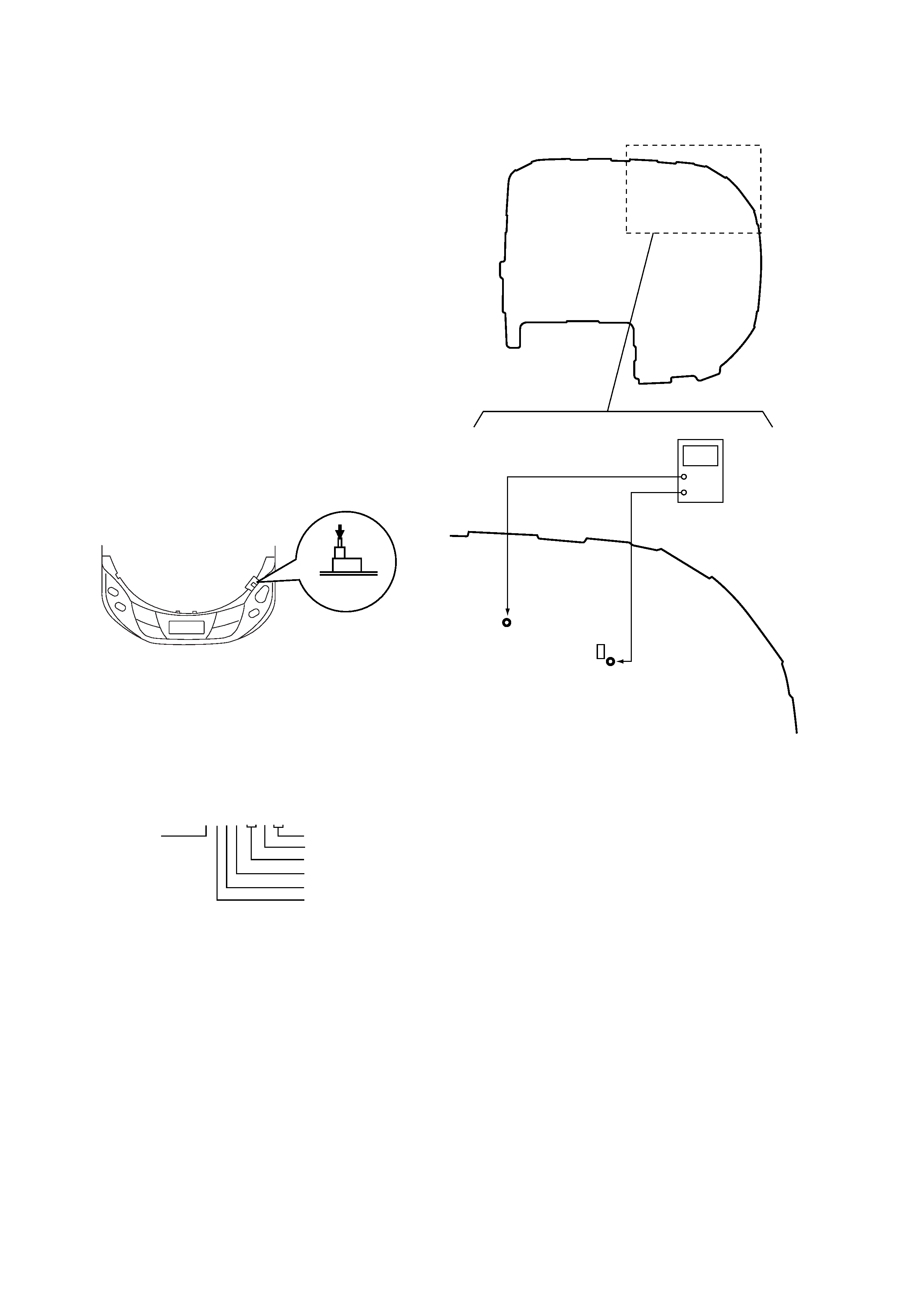
Method-1 (In the service mode or normal operation) :
Emission of the laser diode is visually checked.
1. Open the upper lid.
2. Push the S801 as shown in Fig. 1 .
3. Check the object lens for confirming normal emission of the
laser diode. If not emitting, there is a trouble in the automatic
power control circuit or the optical pick-up. During normal
operation, the laser diode is turned ON about 2.5 seconds for
focus searching.
Fig.1 Method to push S801
Method-2 (In the service mode or normal operation) :
Check the value of current flowing in the laser diode.
1. Remove the upper panel.
2. Read the current printed on the rear side of the optical pick-up.
(Print on the rear side of the optical pick-up)
3. Connect a level meter as shown in Fig. 2
4. Press the ^ key.
5. Calculate the current value by the reading of the digital voltmeter
Reading of the tester (V)
÷ 4.7 ( ) = current value (A)
(Example) Reading of the digital voltmeter of 0.2256 V :
0.2256 V
÷ 4.7 = 0.048 (A) = 48 mA
6. Check that the current value is within the following range.
·
Current value of the label
mA(25
°C)
Variation by temperature : 0.4mA /
°C
Current increases with as temperature increases.
Current decreases with as temperature decreases.
If the current is more than the range above, there is a trouble in the
automatic power control circuit or the laser diode is in deterioration.
If less than the range, a trouble exists in the automatic power control
circuit or the optical pick-up.
S801
AC2211397
year
version
month
A : less than 48 mA
current value
date
line No.
shift No.
[MAIN BOARD] (Conductor side)
Fig.2 Digital Voltmeter Connecting Location
TP506
TP506
TP547
TP547
Q501
+
digital voltmeter
-- 5 --
SECTION 2
GENERAL
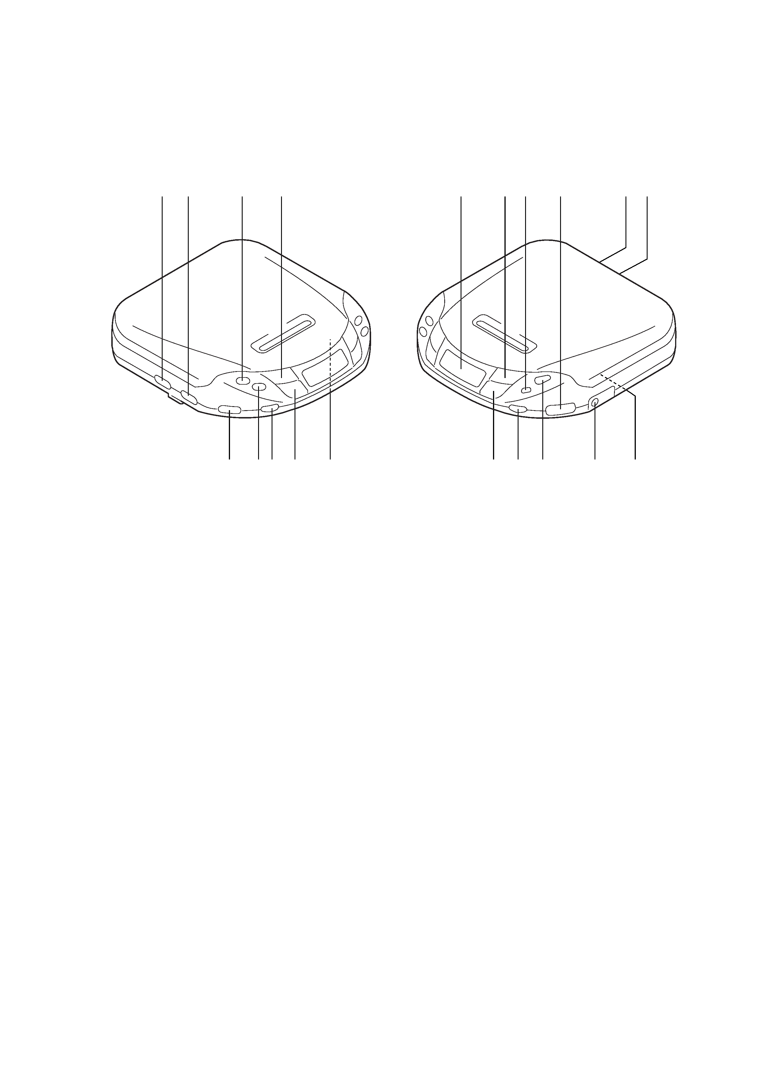
LOCATION AND FUNCTION OF CONTROLS
1
!¡
!TM
!¢
!
!§
2
34
5
6 7
8
9 !º
!£
!¶
!·
!ª
@º
1 DX/LOCAL (US, Canadian, E92)
MONO/STEREO
(Except US, Canadian, E92, Argentine) switch
2 RESUME switch
3 PLAY MODE, TUNING + button
4 + button
5 Display panel
6 ^ button
7 RADIO, BAND button
8 VOLUME control
9 LINE OUT jack
!º DC IN 4.5V jack
!¡ HOLD switch
!TM REPEAT/ENTER, TUNING + button
!£ MEMORY/ESP button
!¢ = button
! AVLS switch
!§ p RADIO OFF button
!¶ SOUND button
!· OPEN button
!ª 2 headphones jack
@º 9k/10k switch
(Except AEP, UK, French, Saudi Arabia model)