Ver 1.2 2001.02
D-EG5/EG5CK/EG7
SERVICE MANUAL
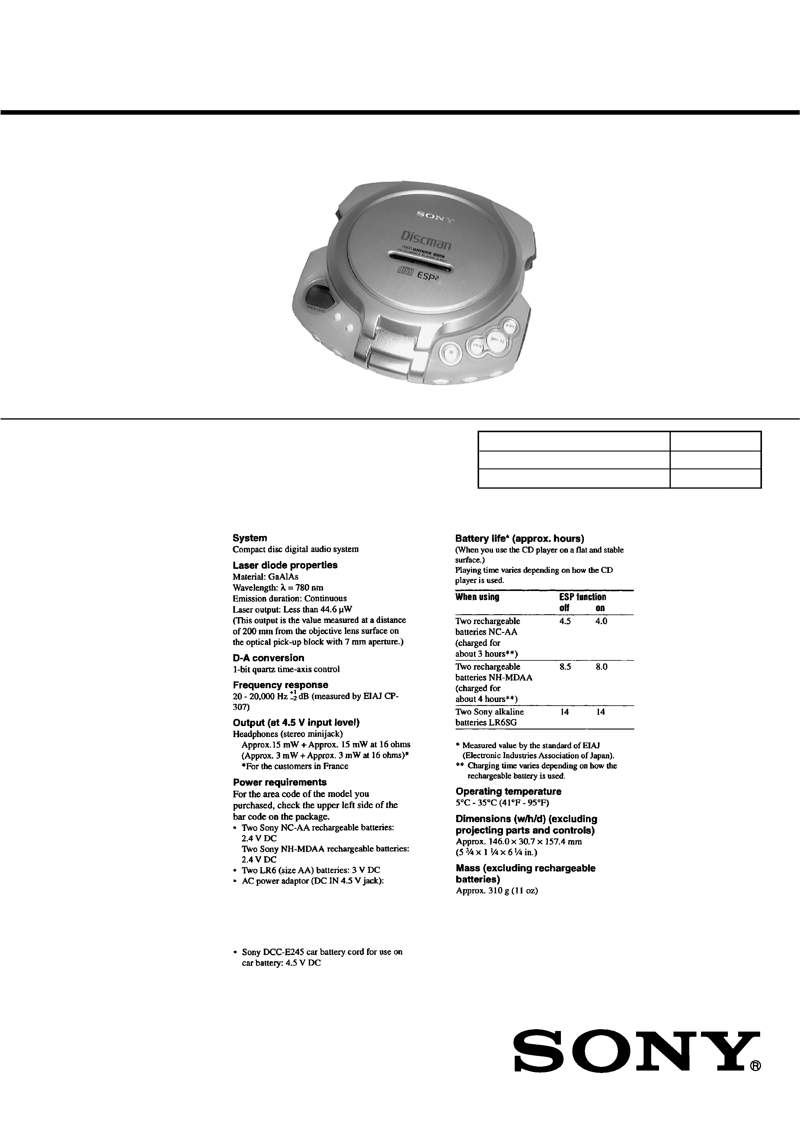
PORTABLE CD PLAYER
SPECIFICATIONS
US Model
D-EG7
Canadian Model
D-EG5/EG5CK/EG7
AEP Model
UK Model
E Model
Australian Model
D-EG7
Photo : D-EG7
Model Name Using Similar Mechanism
NEW
CD Mechanism Type
CDM-2911AAA
Optical Pick-up Type
DAX-11A2
US, Canadian model: 120 V, 60 Hz
AEP, French, German, East European,
E13 model:220 - 230 V, 50/60 Hz
UK model: 230 - 240 V, 50 Hz
Australian model: 240 V, 50 Hz
Continued on page 2
9-927-107-12
2001B0200-1
© 2001.1
Sony Corporation
Audio Entertainment Group
General Engineering Dept.
2
Specifications ............................................................................ 1
1. SERVICING NOTES .................................................... 3
2. GENERAL
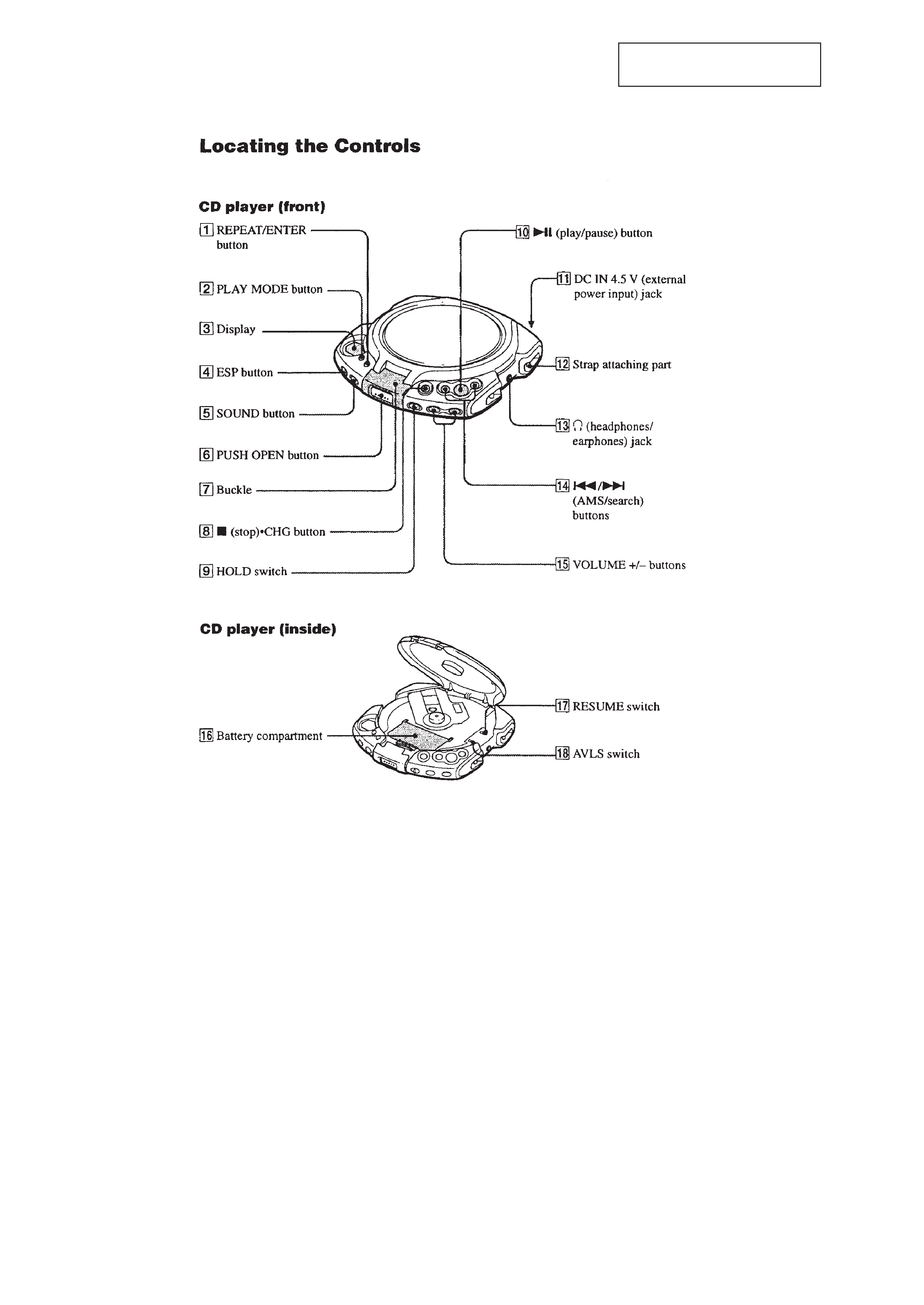
Locating the Controls ......................................................... 4
3. DISASSEMBLY
3-1. Upper Lid ASSY ......................................................... 5
3-2. Cabinet (Front), Cabinet (Rear) .................................. 5
3-3. MD ASSY ................................................................... 6
3-4. Spindle Motor (M902), Optical Pick-up,
Sled Motor (M901) ..................................................... 6
3-5. Main Board ................................................................. 6
4. SERVICE MODE ........................................................... 7
5. ADJUSTMENS .............................................................. 8
6. DIAGRAMS
6-1. Explanation of IC Terminals ...................................... 11
6-2. Block Diagram .......................................................... 13
6-3. Printed Wiring Boards .............................................. 16
6-4. Schematic Diagram ................................................... 19
7. EXPLODED VIEWS
7-1. Cabinet (Front) Section ............................................ 28
7-2. Cabinet (Rear) Section .............................................. 29
7-3. Optical pick-up Section (CDM-2911AAA) .............. 30
8. ELECTRICAL PARTS LIST .................................... 31
ATTENTION AU COMPOSANT AYANT RAPPORT
À LA SÉCURITÉ!
LES COMPOSANTS IDENTIFIÉS PAR UNE MARQUE
! SUR LES
DIAGRAMMES SCHÉMATIQUES ET LA LISTE DES PIÈCES
SONT CRITIQUES POUR LA SÉCURITÉ DE FONCTIONNEMENT.
NE REMPLACER CES COMPOSANTS QUE PAR DES PIÈCES
SONY DONT LES NUMÉROS SONT DONNÉS DANS CE MANUEL
OU DANS LES SUPPLÉMENTS PUBLIÉS PAR SONY.
SAFETY-RELATED COMPONENT WARNING!!
COMPONENTS IDENTIFIED BY MARK
! OR DOTTED LINEWITH
MARK
!ON THE SCHEMATIC DIAGRAMS AND IN THE PARTS
LIST ARE CRITICAL TO SAFE OPERATION.
REPLACE THESE COMPONENTS WITH SONY PARTS WHOSE
PART NUMBERS APPEAR AS SHOWN IN THIS MANUAL OR IN
SUPPLEMENTS PUBLISHED BY SONY.
Flexible Circuit Board Repairing
· Keep the temperature of the soldering iron around 270°C during
repairing.
· Do not touch the soldering iron on the same conductor of the
circuit board (within 3 times).
· Be careful not to apply force on the conductor when soldering or
unsoldering.
Notes on chip component replacement
· Never reuse a disconnected chip component.
· Notice that the minus side of a tantalum capacitor may be dam-
aged by heat.
TABLE OF CONTENTS
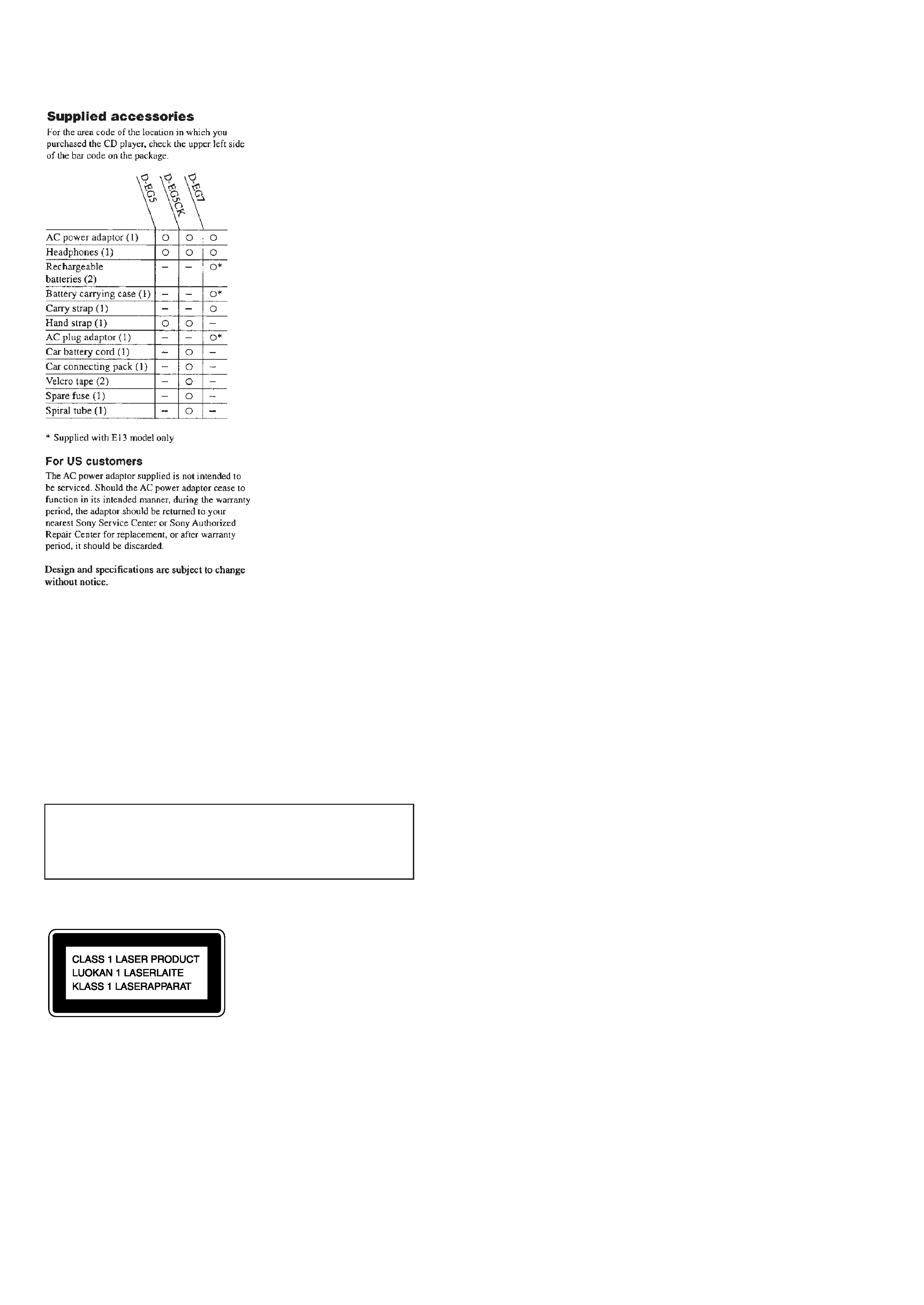
This Compact Disc player is
classified as a CLASS 1 LASER
product.
The CLASS 1 LASER
PRODUCT label is located on
the rear exterior.
CAUTION
Use of controls or adjustments or performance of procedures other
than those specified herein may result in hazardous radiation
exposure.
Laser component in this product is capable of emitting
radiation exceeding the limit for Class 1.
DANGER
Invisible laser radiation when open and interlock failed or defeated.
Avoid direct exposure to beam.
3
The laser diode in the optical pick-up block may suffer electrostatic
breakdown because of the potential difference generated by the charged
electrostatic load, etc. on clothing and the human body. During repair,
pay attention to electrostatic breakdown and also use the procedure in
the printed matter which is included in the repair parts.
The flexible board is easily damaged and should be handled with care.
NOTES ON LASER DIODE EMISSION CHECK
The laser beam on this model is concentrated so as to be focused on the
disc reflective surface by the objective lens in the optical pick-up block.
Therefore, when checking the laser diode emission, observe from more
than 30cm away from the objective lens.
Before Replacing the Optical pick-up Block
Please be sure to check thoroughly the parameters as per the "Optical
pick-up Block Checking Procedure" (Part No. : 9-960-027-11) issued
separately before replacing the optical Pick-up block.
Note and specifications required to check are given below.
· FOK output : IC501 !TM pin
When checking FOK, remove the lead wire to disc motor.
· S curve P-to-P value : 0.9 1.5Vp-p IC501 #¡pin. (Connect pin !TM
of IC501 (TP880) and 3of IC501 (GND) with a jumper wire).
When checking S curve P-to-P value, remove the lead wire to disc
motor.
· Adjusted part for focus gain adjustment : RV503
· RF signal P-to-P value : 0.8 1.2Vp-p
· Traverse signal P-to-P value : 1.0 2.4Vp-p
· The repairing grating holder is impossible.
· Adjusted part for tracking gain adjustment : RV502
SECTION 1
SERVICING NOTES
Laser Diode Checking Methods
During normal operation of the equipment, emission of the laser diode
is prohibited unless the upper panel is closed while turning ON the S801
(push switch type).
The following two checking methods for the laser diode are operable.
Method-1 (In the service mode or normal operation) :
Emission of the laser diode is visually checked.
1. Open the upper lid.
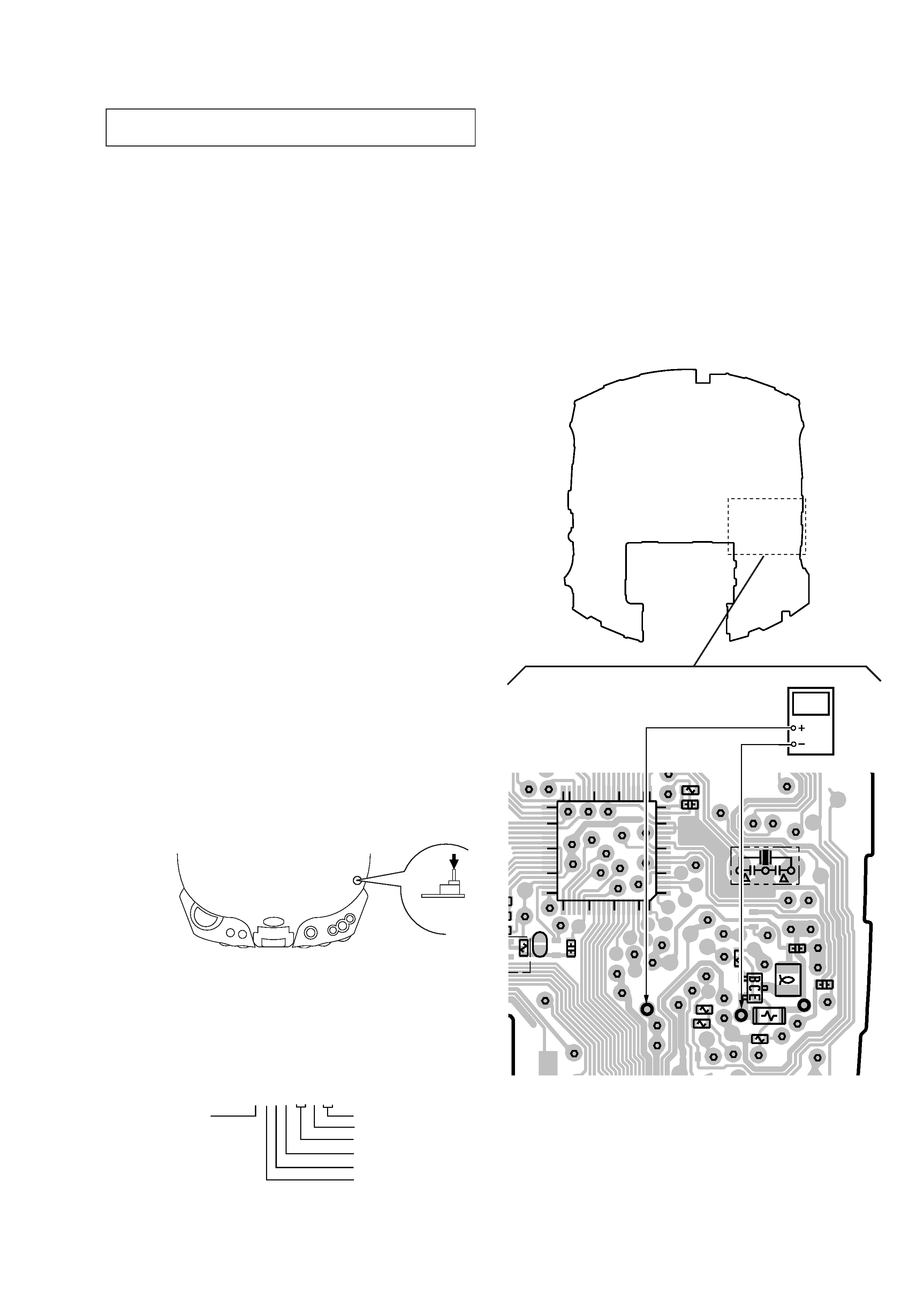
2. Push the S801 as shown in Fig. 1-1 .
3. Check the object lens for confirming normal emission of the laser
diode. If not emitting, there is a trouble in the automatic power
control circuit or the optical pick-up. During normal operation, the
laser diode is turned ON about 2.5 seconds for focus searching.
Fig. 1-1 Method to push S801
Method-2 (In the service mode or normal operation) :
Check the value of current flowing in the laser diode.
1. Remove the upper panel.
2. Read the current printed on the rear side of the optical pick-up.
(Print on the rear side of the optical pick-up)
3. Connect a digital voltmeter as shown in Fig. 1-2
4. Press the
^ key.
Fig. 1-2 Digital Voltmeter Connecting Location
NOTES ON HANDLINGTHE OPTICAL PICK-UP BLOCK OR
BASE UNIT
AC2211397
year
version
month
A : less than 48 mA
current value
date
line No.
shift No.
[MAIN BOARD] (Side B)
1
5
10
15
18
19
25
30
36
37
40
45
50
54
55
60
65
70 72
C549
TP534
TP505
TP502
R509
C806
R510
Q501
L502
C516
R506
R507
R505
TP503
TP506
TP547
TP511
TP508
TP518
C879
R809
P822
80
R806
7
TP532
TP501
TP555
TP821
TP507
TP512
TP523
IC801
X801
TP816
(TEST)
TP506
digital voltmeter
TP547
S801
5. Calculate the current value by the reading of the digital voltmeter.
Reading of the tester (V) ÷ 4.7 (
) = current value (A)
(Example) Reading of the digital voltmeter of 0.2256 V :
0.2256 V ÷ 4.7
= 0.048 (A) = 48 mA
6. Check that the current value is within the following range.
+5
· Current value of the label -11 mA(25
°C)
Variation by temperature : 0.4mA /
°C
Current increases with temperature increased.
Current decreases with temperature decreased.
If the current is more than the range above, there is a trouble in the
automatic power control circuit or the laser diode is in deterioration.
If less than the range, a trouble exists in the automatic power control
circuit or the optical pick-up.
4
SECTION 2
GENERAL
This section is extracted from
instruction manual.
5
SECTION 3
DISASSEMBLY
Note : Follow the disassembly procedure in the numerical order given.
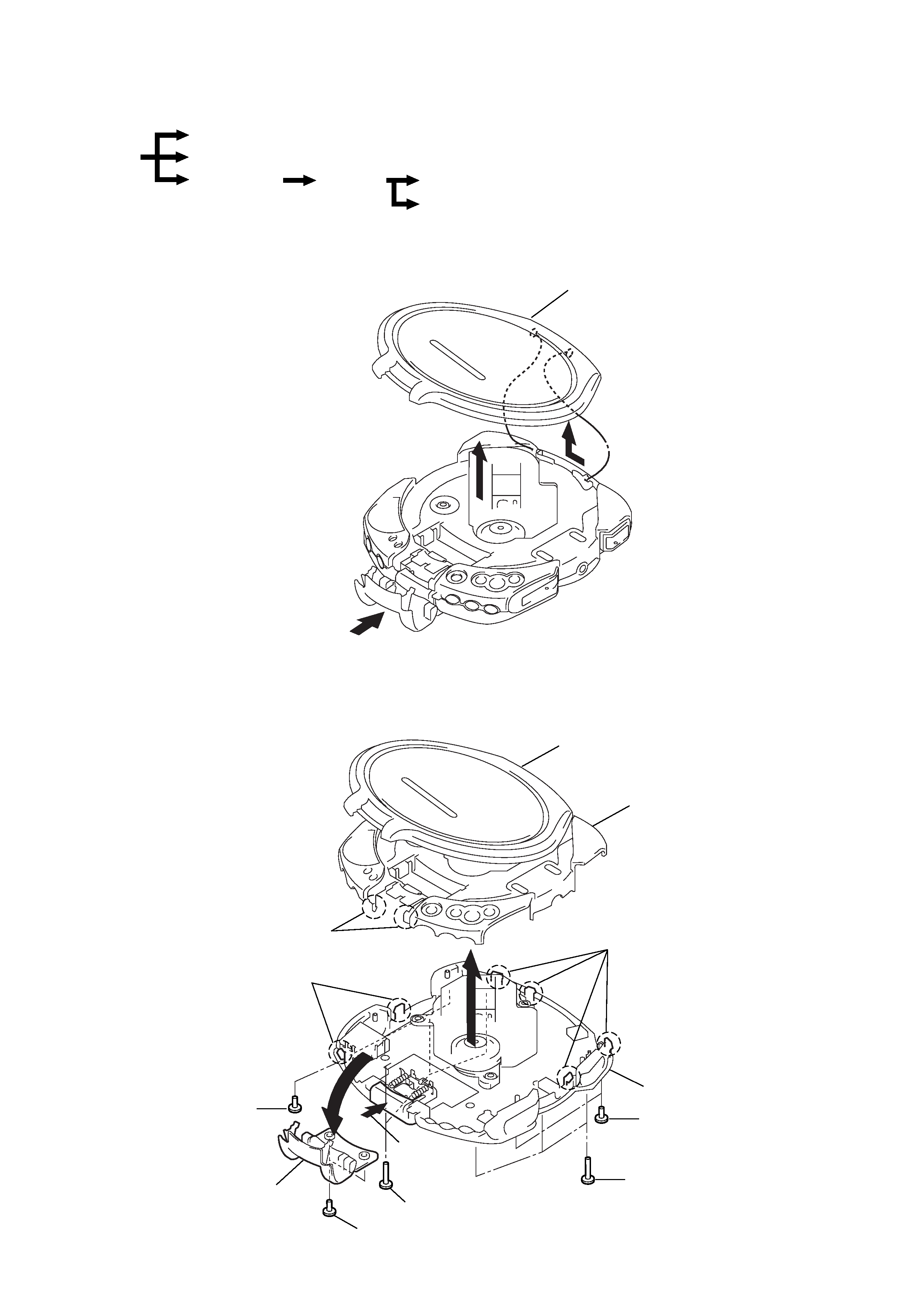
3-1. UPPER LID ASSY
3-2. CABINET (FRONT), CABINET (REAR)
Upper Lid ASSY
Cabinet (Front)
MD ASSY
Set
Spindle motor (M902), Optical Pick-up, Sled motor (M901)
Main board
Cabinet (Rear)
Upper lid ASSY
3
1 OPEN
2
1 Screws (B2x10)
5
9
2 Screws (B2)
2 Screws (B2)
3 Screws (B2)
Cabinet (Front)
Buckle ASSY
Upper lid ASSY
1 Screws (B2x10)
8 Claws
7 Claws
6 Claws
Cabinet (Rear)
4 OPEN
r
The equipment can be removed using the following procedure.