MICROFILM
SERVICE MANUAL
COMPACT DISC COMPACT PLAYER
US Model
AEP Model
UK Model
E Model
Australian Model
D-E905
Tourist Model
D-E900
Model Name Using Similar Mechanism
NEW
CD Mechanism Type
CDM-2501DCA
Optical Pick-Up Name
DAX-01D
SPECIFICATIONS
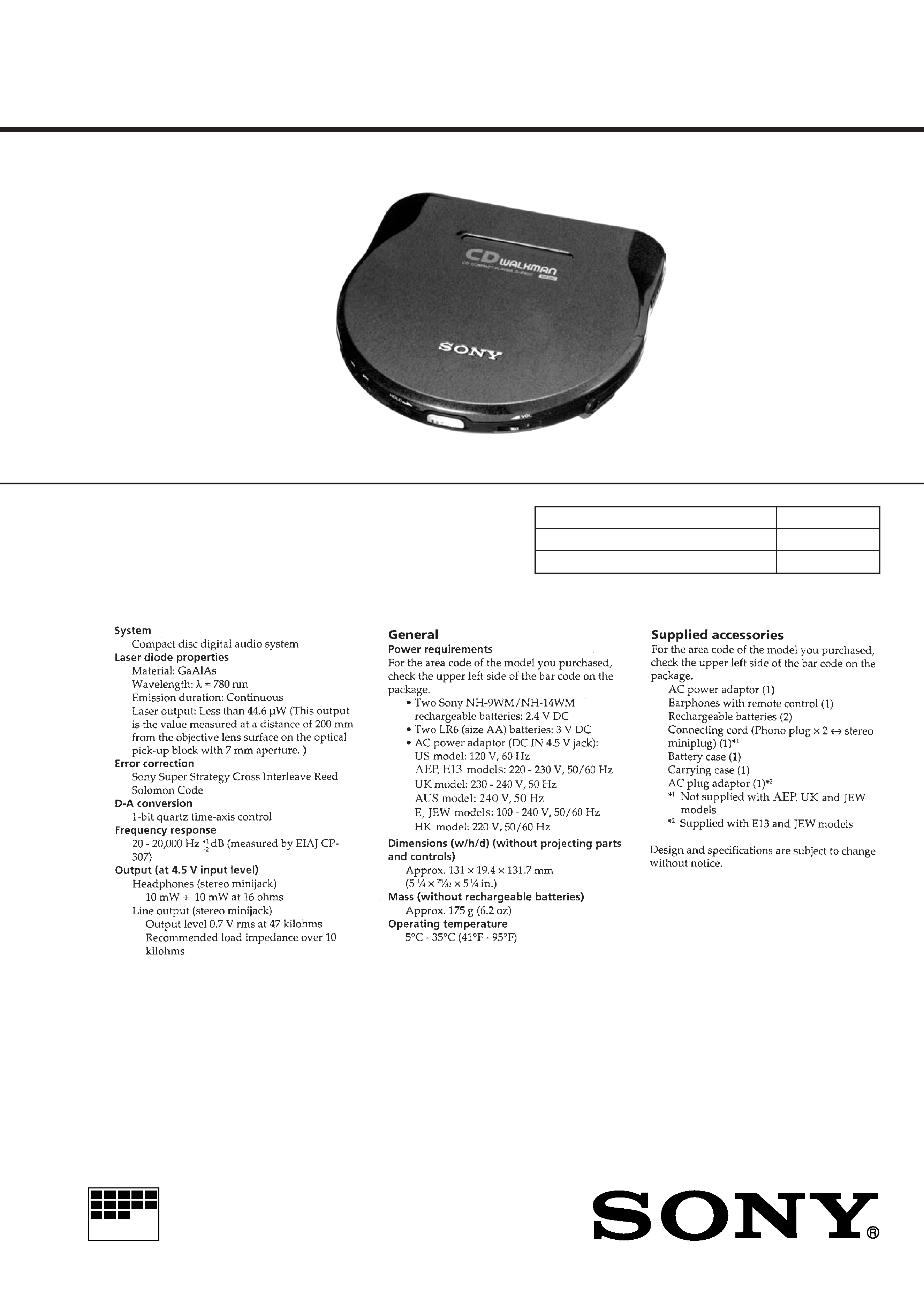
D-E900/E905
Photo: D-E900
· Abbreviation
E13 : 220-230 V AC area in E model
HK : Hong Kong
JEW : Tourist
AUS : Australian
2
TABLE OF CONTENTS
1.
SERVICING NOTES ................................................ 3
2.
GENERAL ................................................................... 4
3.
DISASSEMBLY ......................................................... 7
4.
SERVICE MODE ....................................................... 8
5.
ELECTRICAL ADJUSTMENTS ......................... 9
6.
DIAGRAMS
6-1. Block Diagram ................................................................ 13
6-2. Printed Wiring Board ...................................................... 16
6-3. Schematic Diagram ......................................................... 19
6-4. IC Pin Function Description ........................................... 28
7.
EXPLODED VIEWS ................................................ 30
8.
ELECTRICAL PARTS LIST ............................... 33
Flexible Circuit Board Repairing
· Keep the temperature of the soldering iron around 270 °C dur-
ing repairing.
· Do not touch the soldering iron on the same conductor of the
circuit board (within 3 times).
· Be careful not to apply force on the conductor when soldering
or unsoldering.
Notes on chip component replacement
· Never reuse a disconnected chip component.
· Notice that the minus side of a tantalum capacitor may be dam-
aged by heat.
SAFETY-RELATED COMPONENT WARNING!!
COMPONENTS IDENTIFIED BY MARK
! OR DOTTED
LINE WITH MARK
! ON THE SCHEMATIC DIAGRAMS
AND IN THE PARTS LIST ARE CRITICAL TO SAFE
OPERATION. REPLACE THESE COMPONENTS WITH
SONY PARTS WHOSE PART NUMBERS APPEAR AS
SHOWN IN THIS MANUAL OR IN SUPPLEMENTS PUB-
LISHED BY SONY.
CAUTION
Use of controls or adjustments or performance of procedures
other than those specified herein may result in hazardous ra-
diation exposure.
This appliance is classified as a CLASS 1 LASER product.
The CLASS 1 LASER PRODUCT MARKING is located on
the rear exterior.
3
SECTION 1
SERVICING NOTES
NOTES ON HANDLING THE OPTICAL PICK-UP
BLOCK OR BASE UNIT
The laser diode in the optical pick-up block may suffer electro-
static breakdown because of the potential difference generated by
the charged electrostatic load, etc. on clothing and the human body.
During repair, pay attention to electrostatic breakdown and also
use the procedure in the printed matter which is included in the
repair parts.
The flexible board is easily damaged and should be handled with
care.
Befor Replacing the Optical Pick-Up Block
Please be sure to check thoroughly the parameters as par the "Op-
tical Pick-Up Block Checking Procedures" (Part No.: 9-960-027-
11) issued separately before replacing the optical pick-up block.
Note and specifications required to check are given below.
· FOK output: IC501 !TM pin
When checking FOK, remov the lead wire to disc motor.
· S curve P-to-P value: 2.5 Vp-p IC501 #¡ pin
When checking S curve P-to-P value, remove the lead wire to
disc motor.
· RF signal P-to-P value: 0.8 - 1.2 Vp-p
· Traverse signal P-to-P value: 1 - 2.6 Vp-p
· The repairing grating holder is impossible.
· Adjusted part for tracking gain adjustment: RV504
NOTES ON LASER DIODE EMISSION CHECK
The laser beam on this model is concentrated so as to be focused
on the disc reflective surface by the objective lens in the optical
pick-up block. Therefore, when checking the laser diode emis-
sion, observe from more than 30 cm away from the objective lens.
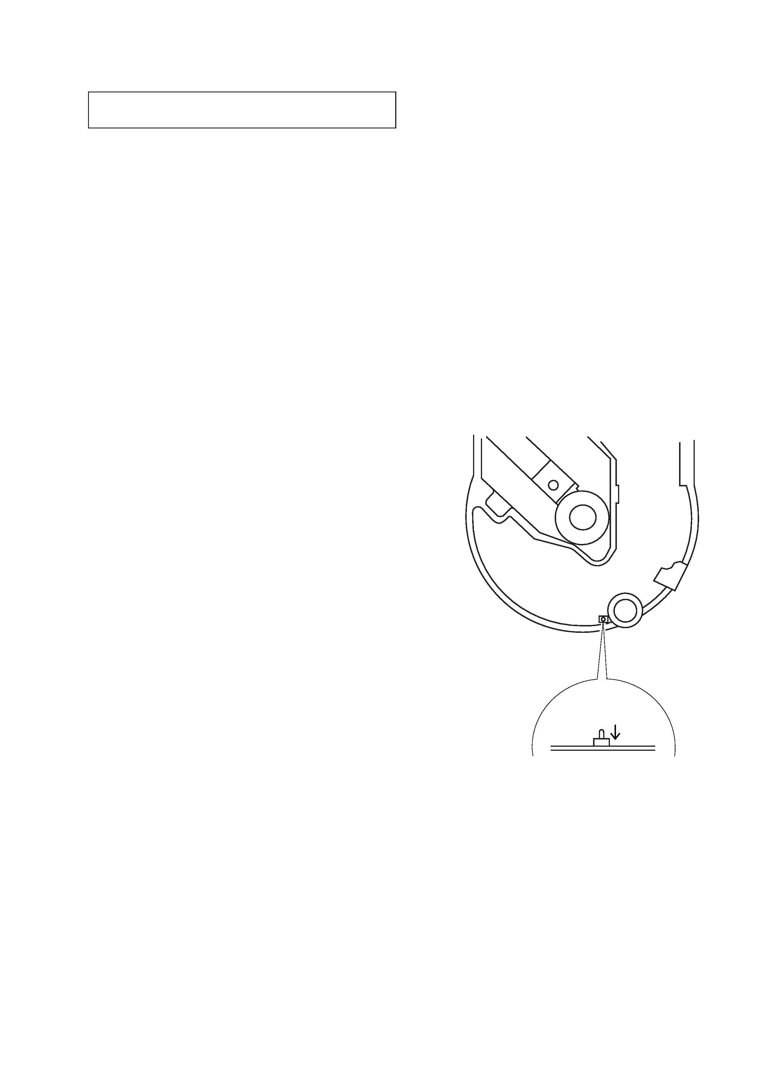
Laser Diode Checking Methods
During normal operation of the equipment, emission of the laser
diode is prohibited unless the upper panel is closed while turning
ON the S809 (push switch type).
The following two checking methods for the laser diode are oper-
able.
· Method (In the service mode or normal operation):
Emission of the laser diode is visually checked.
1. Open the upper lid.
2. Push the S809 as shown in Fig. 1.
3. Press the
^ key.
4. Check the object lens for confirming normal emission of the
laser diode. If not emitting, there is a trouble in the automatic
power control circuit or the optical pick-up.
During normal operation, the laser diode is turned ON about
10 seconds for focus searching.
S809
Fig. 1
Method to push the S809
4
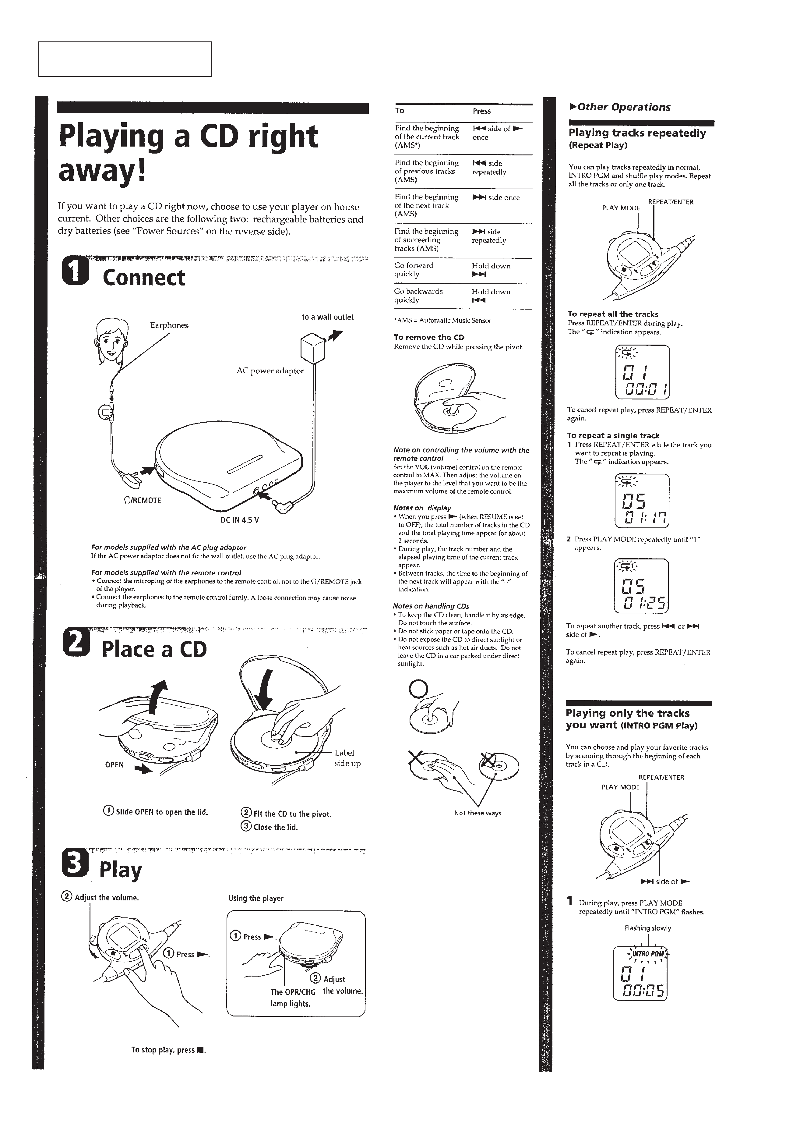
SECTION 2
GENERAL
This section is extracted from
instruction manual.
5