Ver 1.3 1999.12
With SUPPLEMENT 1
(9-926-932-81)
With SUPPLEMENT 2
(9-926-932-82)
MICROFILM
D-E440/E441/E441SR/E443/E445/
E446CK/E449CK
SERVICE MANUAL
COMPACT DISC COMPACT PLAYER
SPECIFICATIONS
US Model
D-E441/E445/E446CK/E449CK
Canadian Model
D-E441/E445/E446CK
AEP Model
D-E440/E441/E441SR/E443/E445/E446CK
UK Model
D-E441/E441SR/E443/E445/E446CK
E Model
D-E441/E443/E445/E446CK
Australian Model
D-E441/E445/E446CK
Chinese Model
D-E441/E445
Model Name Using Similar Mechanism
NEW
CD Mechanism Type
CDM-2811EAA
Optical Pick-up Type
DAX-11E
CD player
System
Compact disc digital audio system
Laser diode properties
Material: GaAIAs
Wavelength :
= 780 nm
Emission duration: Continuous
Laser output : Less than 44.6
µW (This output
is the value measured at a distance of 200 mm
from the objective lens surface on the optical
pick-up block with 7 mm aperture. )
Error correction
Sony Super Strategy Cross Interleave Reed
Solomon Code
D-A conversion
1-bit quartz time-axis control
Frequency response
20 - 20,000 Hz +1 dB (measured by EIAJ CP-
307)
-2
Output (at 4.5 V input level)
Headphones (stereo minijack)
15 mW + 15 mW at 16 ohms
Line output (stereo minijack)
Output level 0.7 V rms at 47 kilohms
Recommended load impedance over 10
kilohms
General
Power requirements
For the area code of the model you purchased,
check the upper left side of the bar code on the
package.
· Sony BP-DM10 Rechargeable battery:
2.4 V DC, Ni-Cd, 650 mAh
Sony BP-DM20 Rechargeable battery:
2.4 V DC, Ni-MH, 1,200 mAh
· Two LR6 (size AA) batteries: 3 V DC
· AC power adaptor (DC IN 4.5 V jack):
US, Canadian, Central and South America
model: 120 V, 60 Hz
AEP, German, French, EE, E13 model:
220 - 230 V, 50/60 Hz
UK model: 230 - 240 V, 50 Hz
EA model: 110 - 240 V, 50/60 Hz
AUS model: 240 V, 50 Hz
E33 model: 100 - 240 V, 50/60 Hz
Hong Kong model: 220 V, 50/60 Hz
Chinese, Argentine model: 220 V, 50 Hz
· Sony CPM-300P mount plate for use on car
battery : 4.5V DC
Dimensions (w/h/d) (without projecting parts and
controls)
Approx. 129 x 28 x 146 mm
( 51/8 x 11/8 x 53/4 in.)
Mass (without rechargeable battery)
Approx. 220 g (7.8 oz)
Operating temperature
5
°C - 35°C (41°F - 95°F)
Supplied accessories
For the area code of the model you purchased,
check the upper left side of the bar code on the
package.
D-E440
Earphones (1)
D-E441
AC power adaptor (1)
Headphones (1)*1
Earphones (1)*2
AC plug adaptor (1)*3
*1 Supplied with US model
*2 Not supplied with US model
*3 Supplied with E33, E13 and EA models
Photo : D-E441
Continued on page 2
2
Specifications ............................................................................ 1
1. SERVICING NOTES ................................................... 3
2. GENERAL ...................................................................... 4
3. DISASSEMBLY
3-1. Lid Assy, Upper .......................................................... 5
3-2. Cabinet (Front) Assy, Cabinet (Rear) Assy,
MD Assy ..................................................................... 5
3-3. Main Board ................................................................. 6
4. SERVICE MODE .................................................... 7
5. ADJUSTMENTS .......................................................... 8
6. DIAGRAMS
6-1. Explanation of IC Terminals ...................................... 11
6-2. Block Diagram .......................................................... 13
6-3. Printed Wiring Boards .............................................. 16
6-4. Schematic Diagram ................................................... 19
7. EXPLODED VIEWS
7-1. Cabinet Section ......................................................... 28
7-2. Optical Pick-up Section ............................................ 30
8. ELECTRICAL PARTS LIST ................................... 31
ATTENTION AU COMPOSANT AYANT RAPPORT
À LA SÉCURITÉ!
LES COMPOSANTS IDENTIFIÉS PAR UNE MARQUE
! SUR LES
DIAGRAMMES SCHÉMATIQUES ET LA LISTE DES PIÈCES
SONT CRITIQUES POUR LA SÉCURITÉ DE FONCTIONNEMENT.
NE REMPLACER CES COMPOSANTS QUE PAR DES PIÈCES
SONY DONT LES NUMÉROS SONT DONNÉS DANS CE MANUEL
OU DANS LES SUPPLÉMENTS PUBLIÉS PAR SONY.
SAFETY-RELATED COMPONENT WARNING!!
COMPONENTS IDENTIFIED BY MARK
! OR DOTTED LINE WITH
MARK
! ON THE SCHEMATIC DIAGRAMS AND IN THE PARTS
LIST ARE CRITICAL TO SAFE OPERATION.
REPLACE THESE COMPONENTS WITH SONY PARTS WHOSE
PART NUMBERS APPEAR AS SHOWN IN THIS MANUAL OR IN
SUPPLEMENTS PUBLISHED BY SONY.
Flexible Circuit Board Repairing
· Keep the temperature of the soldering iron around 270
°C during
repairing.
· Do not touch the soldering iron on the same conductor of the circuit
board (within 3 times).
· Be careful not to apply force on the conductor when soldering or
unsoldering.
Notes on chip component replacement
· Never reuse a disconnected chip component.
· Notice that the minus side of a tantalum capacitor may be damaged
by heat.
TABLE OF CONTENTS
This Compact Disc player is
classified as a CLASS 1 LASER
product.
The CLASS 1 LASER
PRODUCT label is located on the
bottom exterior.
CAUTION
Use of controls or adjustments or performance of procedures other than
those specified herein may result in hazardous radiation exposure.
DANGER
Invisible laser radiation when open and interlock failed or defeated.
Avoid direct exposure to beam.
D-E441SR
AC power adaptor (1)
Earphones (1)
Active speaker system (1)
D-E443
AC power adaptor (1)
Earphones (1)
Rechargeable battery (1)
AC plug adaptor (1)*
*
Supplied with E33, E13 and EA models
D-E445
AC power adaptor (1)
Headphones with remote control (1) *1
Earphones with remote control (1) *2
Rechargeable battery (1)
AC plug adaptor (1)*3
*1 Supplied with US model
*2 Not supplied with US model
*3 Supplied with E13 model
D-E446CK
AC power adaptor (1)
Headphones (1) *1
Earphones (1) *2
Car battery cord (1)
Car connecting pack (1)
Velcro tape (2)
Spare fuse (1)
Spiral tube (1)
AC plug adaptor (1)*3
*1 Supplied with US model
*2 Not supplied with US model
*3 Supplied with E33, E13 and EA models
D-E449CK
AC power adaptor (1)
Rechargeable battery (1)
Headphones with remote control (1)
Car battery cord (1)
Car connecting pack (1)
Velcro tape (2)
Spare fuse (1)
Spiral tube (1)
Design and specifications are subject to change without notice.
3
The laser diode in the optical pick-up block may suffer electrostatic
breakdown because of the potential difference generated by the charged
electrostatic load, etc. on clothing and the human body. During repair,
pay attention to electrostatic breakdown and also use the procedure in
the printed matter which is included in the repair parts.
The flexible board is easily damaged and should be handled with care.
NOTES ON LASER DIODE EMISSION CHECK
The laser beam on this model is concentrated so as to be focused on the
disc reflective surface by the objective lens in the optical pick-up block.
Therefore, when checking the laser diode emission, observe from more
than 30cm away from the objective lens.
Before Replacing the Optical pick-up Block
Please be sure to check thoroughly the parameters as per the "Optical
pick-up Block Checking Procedure" (Part No. : 9-960-027-11) issued
separately before replacing the optical Pick-up block.
Note and specifications required to check are given below.
· FOK output : IC501 !TM pin
When checking FOK, remove the lead wire to disc motor.
· S curve P-to-P value : 1.2±0.3Vp-p IC501 #¡ pin. (Connect pin !TM of
IC501 (TP880) and 3 of IC501 (GND) with a jumper wire).
When checking S curve P-to-P value, remove the lead wire to disc
motor.
· Adjusted part for focus gain adjustment : RV503
· RF signal P-to-P value : 0.8 1.2Vp-p
· Traverse signal P-to-P value : 1.0 2.4Vp-p
· The repairing grating holder is impossible.
· Adjusted part for tracking gain adjustment : RV502
SECTION 1
SERVICING NOTES
Precautions for Checking Emission of Laser Diode
Laser light of the equipment is focused by the object lens in the optical
pick-up so that the light focuses on the reflection surface of the disc.
Therefore, be sure to keep your eyes more then 30cm apart from the
object lens when you check the emission of laser diode.
Laser Diode Checking Methods
During normal operation of the equipment, emission of the laser diode
is prohibited unless the upper panel is closed while turning ON the S801
(push switch type).
The following two checking methods for the laser diode are operable.
Method-1 (In the service mode or normal operation) :
Emission of the laser diode is visually checked.
1. Open the upper lid.
2. Push the S801 as shown in Fig. 1 .
3. Check the object lens for confirming normal emission of the laser
diode. If not emitting, there is a trouble in the automatic power
control circuit or the optical pick-up. During normal operation, the
laser diode is turned ON about 2.5 seconds for focus searching.
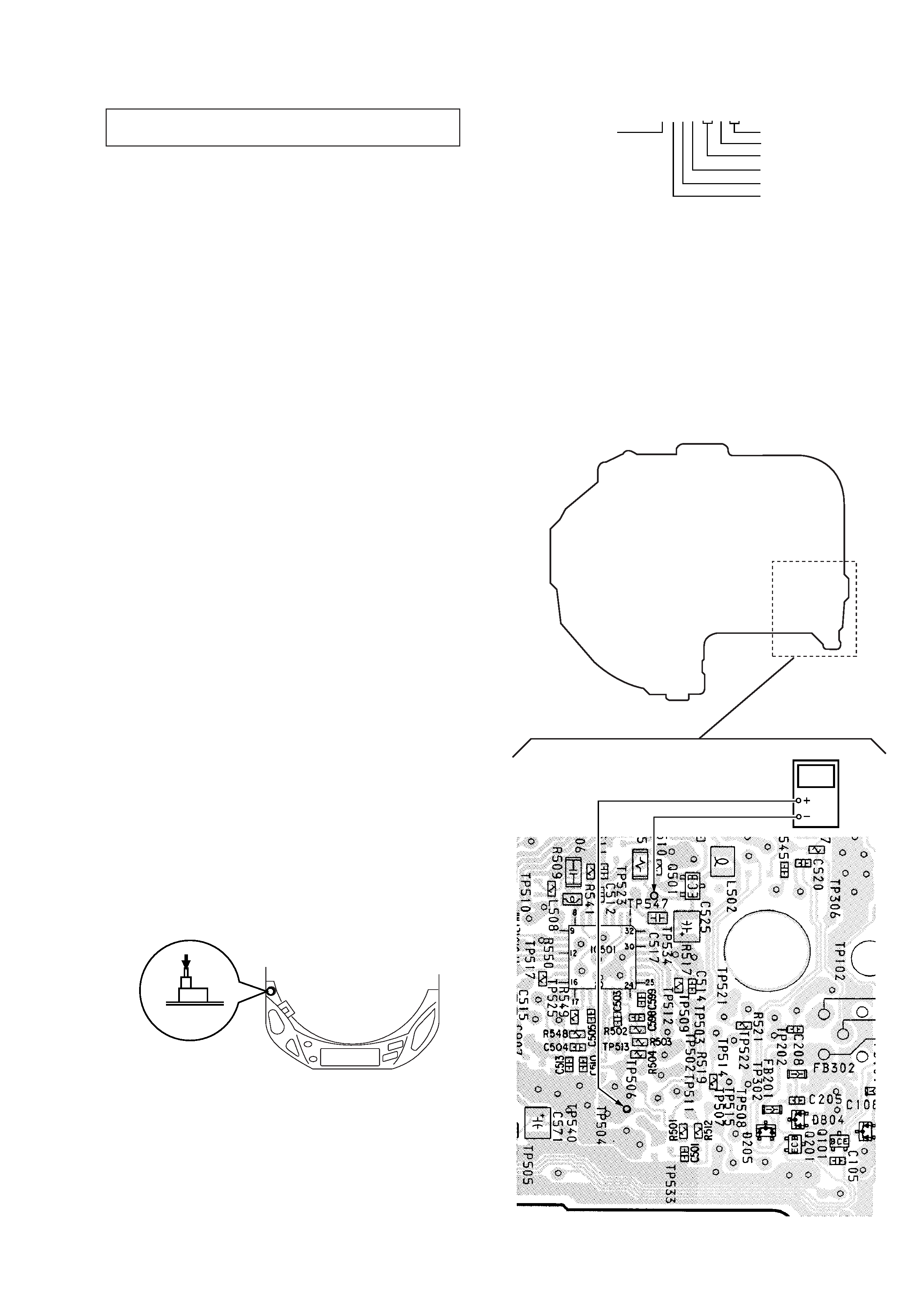
Fig. 2 Digital Voltmeter Connecting Location
NOTES ON HANDLING THE OPTICAL PICK-UP BLOCK OR
BASE UNIT
Method-2 (In the service mode or normal operation) :
Check the value of current flowing in the laser diode.
1. Remove the upper panel.
2. Read the current printed on the rear side of the optical pick-up.
(Print on the rear side of the optical pick-up)
3. Connect a level meter as shown in Fig. 2
4. Press the
^ key.
Fig.1 Method to push S801
AC2211397
year
version
month
A : less than 48 mA
current value
date
line No.
shift No.
5. Calculate the current value by the reading of the digital voltmeter.
Reading of the tester (V) ÷ 4.7 (
) = current value (A)
(Example) Reading of the digital voltmeter of 0.2256 V :
0.2256 V ÷ 4.7
= 0.048 (A) = 48 mA
6. Check that the current value is within the following range.
+5
· Current value of the label -11 mA(25
°C)
Variation by temperature : 0.4mA /
°C
Current increases with temperature increased.
Current decreases with temperature decreased.
If the current is more than the range above, there is a trouble in the
automatic power control circuit or the laser diode is in deterioration.
If less than the range, a trouble exists in the automatic power control
circuit or the optical pick-up.
[MAIN BOARD] (Conductor side)
S801
TP506
digital voltmeter
TP547
4
SECTION 2
GENERAL
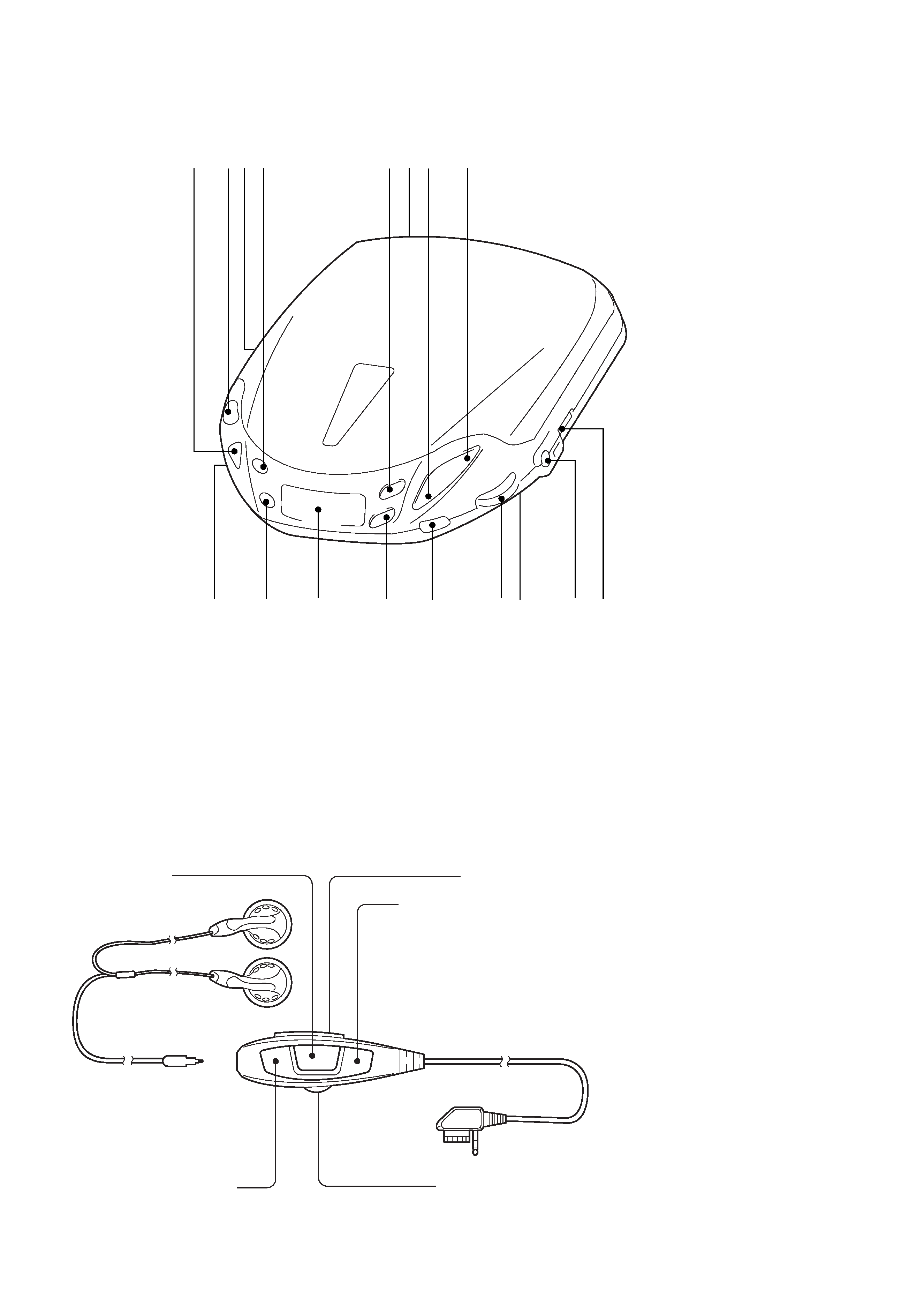
LOCATION AND FUNCTION OF CONTROLS
Volume control RM-DM29 : (D-E445/E449CK)
1
ESP (Electronic Shock Protection) button
2
OPEN button
3
DC IN 4.5V jack
4
PLAY MODE button
5
+ FF button
6
LINE OUT jack
7
p STOP button
8
^ Play/pause button
9
OFF-RESUME-ON switch
0
2 /Remote jack
!¡
AVLS switch
!TM
VOLUME control
!£
Sound switch
!¢
= FR button
!
Information display panel
!§
REPEAT/ENTER button
!¶
HOLD switch
1234
5
7
8
9
0
!¡
!TM
!£
!¢
!
!§
!¶
6
p
^
HOLD**
VOL (volume)
Remote control
Earphones
+
= (AMS*/search)
+
( (play) ·
+
+ (AMS*/search)
+
p (stop)
*
Automatic Music Sensor
** When you are not using the remote
control, slide HOLD in the direction of the
arrow to prevent any accidental operation.
To unlock, slide HOLD back.
Note
· Use only the supplied remote control. You
cannot operate this player with the remote
control supplied with other models.
5
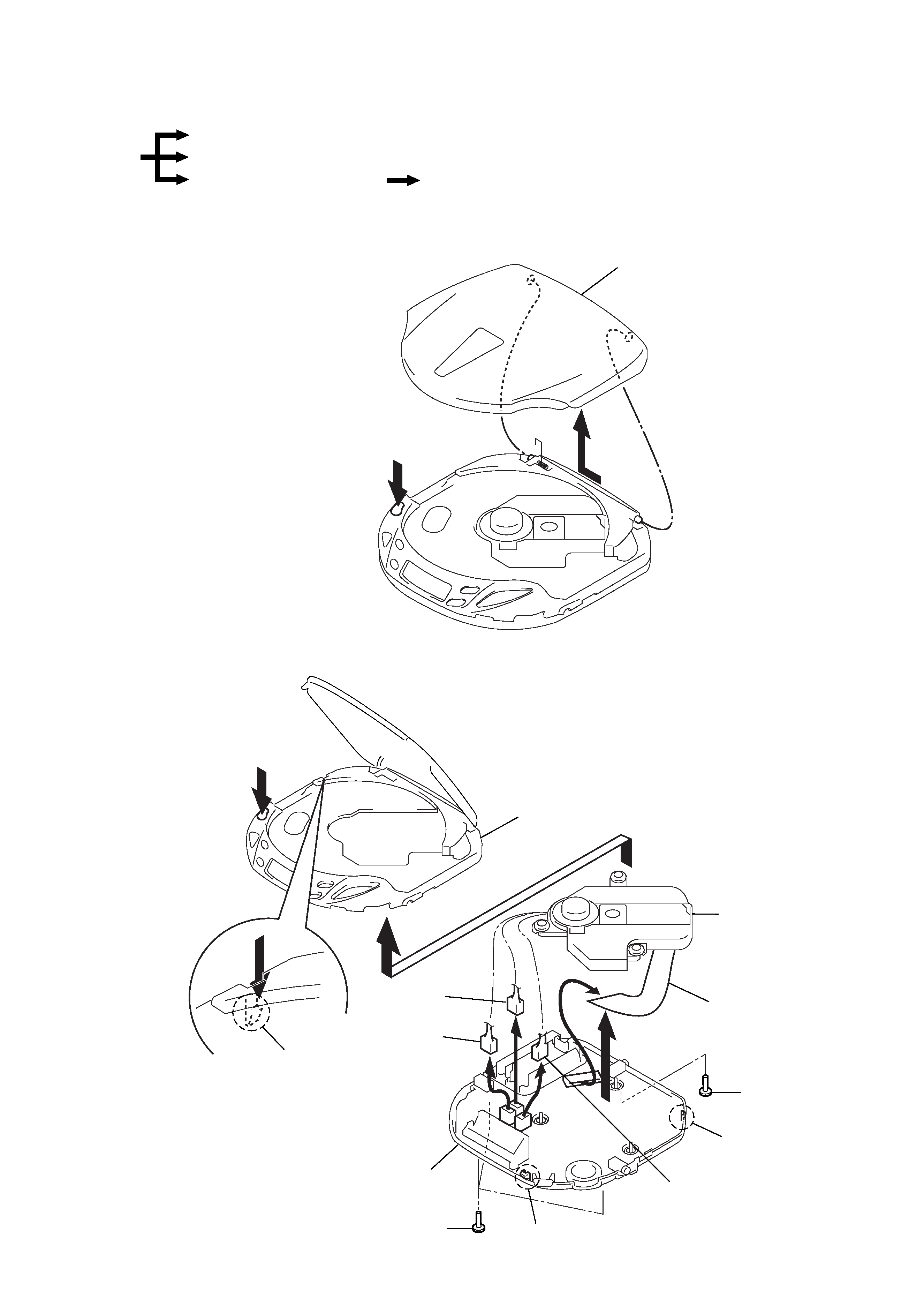
SECTION 3
DISASSEMBLY
Note : Follow the disassembly procedure in the numerical order given.
3-1. LID ASSY, UPPER
3-2. CABINET (FRONT) ASSY, CABINET (REAR) ASSY, MD ASSY
Lid ASSY, Upper
Cabinet (Front) ASSY
Cabinet (Rear) ASSY, MD ASSY
Set
Main board
Lid ASSY, Upper
2
1 OPEN
1 Screws (1.4x2.5)
1 Screw
(1.4x2.5)
!º CN501
4 Claw
4 Claw
Claw
8 CN702
7 CN701
9 CN703
6
5
3
MD ASSY
Cabinet (Front) ASSY
Cabinet (Rear)
ASSY
2 OPEN
r
The equipment can be removed using the following procedure.