Sony
Corporation
CCD-TR
V89E/TR
V95/TR
V95E/TR
V95PK/TR
V99/TR
V99E
RMT
-708/717
SER
VICE
MANUAL
CCD-TRV89E/TRV95/TRV95E/TRV95PK/
TRV99/TRV99E
RMT-708/717
SERVICE MANUAL
MICROFILM
For MECHANISM ADJUSTMENTS, refer to
the "8mm Video MECHANICAL ADJUSTMENT
MANUAL VII" (9-973-801-11).
SPECIFICATIONS
H
VIDEO CAMERA RECORDER
-- Continued on next page --
B MECHANISM
Photo : CCD-TRV99E
: RMT-717
Video camera recorder
System
Video recording system
CCD-TRV95/TRV95PK/TRV99 :
4 rotary heads (SP/LP independent heads)
CCD-TRV89E/TRV95E/TRV99E :
2 Rotary heads
Helical scanning FM system
Audio recording system
Rotary heads, FM system
Video signal
CCD-TRV95 (US, CND)/TRV99 :
NTSC color, CCIR standards
CCD-TRV95 (E, JE)/TRV95PK :
NTSC color, EIA standards
CCD-TRV89E/TRV95E/TRV99E :
PAL color CCIR standards
Usable cassette
8mm video format cassette
Hi8 or standard 8
Recording / Playback time
CCD-TRV95/TRV95PK/TRV99 :
(using 120 min. cassette)
SP mode: 2 hours
LP mode: 4 hours
CCD-TRV89E/TRV95E/TRV99E :
(using 90 min. cassette)
SP mode: 1 hours and 30 minutes
LP mode: 3 hours
Fastforward/rewind time
CCD-TRV95/TRV95PK/TRV99 :
(using 120 min. cassette) Approx. 5 min.
CCD-TRV89E/TRV95E/TRV99E :
(using 90 min. cassette) Approx. 5 min.
Image device
CCD (Charge Coupled Device)
Viewfinder
Electronic viewfinder
CCD-TRV89E : Monochrome
CCD-TRV95/TRV95E/TRV95PK/
TRV99/TRV99E :
Color 113,578 (521 x 218)
Lens
Combined power zoom lens
Filter diameter 17/16 in. (37 mm)
CCD-TRV95 (US,CND)/TRV95E/
TRV99 :
18 x (Optical), 72 x (Digital)
CCD-TRV89E/TRV95 (E, JE)/
TRV95PK/TRV99E :
18 x (Optical), 220 x (Digital)
Focal distance
3/16 - 8 in. (4.1 - 73.8 mm)
When converted to a 35 mm still
camera
1 7/8 - 33 1/2 in. (47.2 - 850 mm)
Color temperature
Auto
Minimum illumination
0.7 lux (F 1.4)
0 lux (in NightShot mode)*
* Object invisible for the dark can be
shot with infrared lighting.
Illumination range
0.7 lux to 100,000 lux
Recommended illumination
More than 100 lux
LCD screen
Picture
4 inches measured diagonally
3 1/4 x 2 3/8 in.(80.7 x 58.9 mm)
On-screen display
TN LCD/TFT active matrix method
Total dot number
112.086 (479 x 234)
Input and output connectors
S video input/output
(CCD-TRV89E/TRV95/TRV95PK/
TRV99/TRV99E only)
4-pin mini DIN
Luminance signal :
1 Vp-p, 75 ohms, unbalanced
Chrominance signal
CCD-TRV95/TRV95PK/TRV99 :
0.286 Vp-p, 75 ohms, unbalanced
CCD-TRV89E/TRV95E/TRV99E :
0.3 Vp-p, 75 ohms, unbalanced
Video input/output
(CCD-TRV89E/TRV95/TRV95PK/
TRV99/TRV99E only)
Phono jack, 1 Vp-p, 75 ohms, unbalanced
Audio input/output
(CCD-TRV89E/TRV95/TRV95PK/
TRV99/TRV99E only)
Phono jacks (2: stereo L and R) 327
mV, (at output impedance 47 kilohms)
impedance less than 2.2 kilohms
RFU DC OUT
Special minijack, DC 5V
Headphone jack
Stereo minijack (ø 3.5 mm)
LANC control jack
Stereo mini-minijack (ø 2.5 mm)
MIC jack
Mini jack, 0.388mV low impedance
with 2.5 to 3.0 V DC, output impedance
6.8 kilohms (ø 3.5 mm) Stereo type
Speaker
Dynamic speaker
Intelligent accessory shoe
8-pin connector
General
Power requirements
7.2 V (battery pack)
8.4 V (AC power adaptor)
Sony Corporation
Personal A&V Products Company
9-974-055-11
98C0989-1
Printed in Japan © 1998. 3
Published by Quality Engineering Dept.
(Osaki East)
292
CCD-TRV89E/TRV95/TRV95E/TRV95PK/TRV99/TRV99E
US Model
Canadian Model
CCD-TRV95/TRV99
E Model
CCD-TRV89E/TRV95/TRV95PK/TRV99E
AEP Model
UK Model
CCD-TRV95E
Hong Kong Model
CCD-TRV89E/TRV99E
Tourist Model
CCD-TRV89E/TRV95/TRV99E
Australian Model
Chinese Model
CCD-TRV89E/TRV99E

AC power adaptor
Power requirements
100 -240 V AC, 50/60 Hz
Power consumption
23 W
Output voltage
DC OUT: 8.4 V, 1.5 A in operating mode
Operating temperature
32
°F to 104°F(0°C to 40°C)
Storage temperature
-4
°F to +140°F(-20°C to +60°C)
Dimentions (Approx.)
5 x 1 9/16 x 2 1/2 in.
(125 x 39 x 62 mm)(w/h/d)
excluding projecting parts
Mass (Approx.)
9.8 oz (280 g) excluding power cord
(Main lead)
Design and specifications are subject to
change without notice.
· Abbreviation
CND : Canadian Model
JE : Tourist Model
Average power consumption
(when using the battery pack)
During camera recording using
LCD
CCD-TRV95/TRV95PK/TRV99 : 3.8 W
CCD-TRV89E/TRV95E/TRV99E : 3.9 W
Viewfinder
CCD-TRV95/TRV95PK/TRV99 : 2.6 W
CCD-TRV89E/TRV95E/TRV99E : 2.7 W
Operating temperature
32
°F to 104°F(0°C to 40°C)
Storage temperature
-4
°F to +140°F(-20°C to +60°C)
Dimentions (Approx.)
CCD-TRV89E :
4 3/8 x 5 x 8 1/2 in.
(110 x 124 x 213 mm)(w/h/d)
CCD-TRV95/TRV95E/TRV95PK/
TRV99/TRV99E :
4 3/8 x 5 x 8 1/2 in.
(110 x 125 x 213 mm)(w/h/d)
Mass (Approx.)
2 lb 3 oz (1 kg)
excluding the battery pack, lithium
battery, cassette and shoulder strap
2 lb 6 oz (1.1 kg)
including the battery pack NP-F330,
lithium battery CR2025, cassette and
shoulder strap
Microphone
Stereo type
Supplied accessories
See page 4.
ATTENTION AU COMPOSANT AYANT RAPPORT
À LA SÉCURITÉ!!
LES COMPOSANTS IDENTIFIÉS PAR UNE MARQUE ! SUR LES
DIAGRAMMES SCHÉMATIQUES ET LA LISTE DES PIÈCES SONT
CRITIQUES POUR LA SÉCURITÉ DE FONCTIONNEMENT. NE
REMPLACER CES COMPOSANTS QUE PAR DES PIÈCES SONY
DONT LES NUMÉROS SONT DONNÉS DANS CE MANUEL OU
DANS LES SUPPLÉMENTS PUBLIÉS PAR SONY.
SAFETY-RELATED COMPONENT WARNING !!
COMPONENTS IDENTIFIED BY MARK !OR DOTTED LINE WITH
MARK ! ON THE SCHEMATIC DIAGRAMS AND IN THE PARTS
LIST ARE CRITICAL TO SAFE OPERATION. REPLACE THESE
COMPONENTS WITH SONY PARTS WHOSE PART NUMBERS
APPEAR AS SHOWN IN THIS MANUAL OR IN SUPPLEMENTS
PUBLISHED BY SONY.
1. Check the area of your repair for unsoldered or poorly-soldered
connections. Check the entire board surface for solder splashes
and bridges.
2. Check the interboard wiring to ensure that no wires are "pinched"
or contact high-wattage resistors.
3. Look for unauthorized replacement parts, particularly transistors,
that were installed during a previous repair. Point them out to
the customer and recommend their replacement.
4. Look for parts which, though functioning, show obvious signs
of deterioration. Point them out to the customer and recommend
their replacement.
5. Check the B+ voltage to see it is at the values specified.
6. Flexible Circuit board Repairing
· Keep the temperature of the soldering iron around 270
°C during
repairing.
· Do not touch the soldering iron on the same conductor of the
circuit board (within 3 times).
· Be careful not to apply force on the conductor when soldering
or unsoldering.
SAFETY CHECK-OUT
After correcting the original service problem, perform the following
safety checks before releasing the set to the customer:
2
FOR CAMERA COLOR REPRODUCTION ADJUSTMENT Take a copy CAMERA COLOR REPRODUCTION FRAME
and Parts reference sheets with a clear sheet for use.
CCD-TRV89E/TRV95E/TRV99E
For NTSC model
CCD-TRV95/TRV95PK/TRV99
For PAL model
3
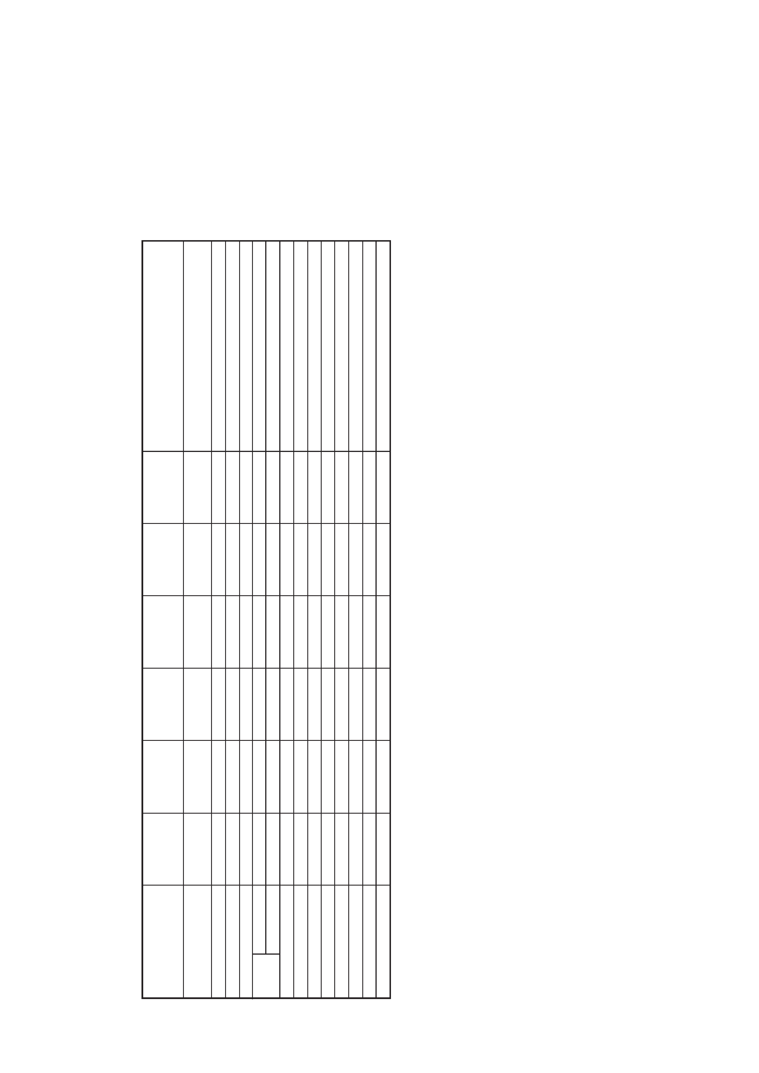
CCD-
TR
V95E
AEP
,UK
PA
L
TYPE
C
RMT
-717
18X
72X
¬
¬
3heads
¬
G
G
¬
G
CCD-
TR
V89E
E,
HK,
A
US,
CN,
JE
PA
L
TYPE
A
RMT
-708
18X
220X
¬
¬
3heads
G
¬
G
G
¬
CCD-
TR
V99E
E,
HK,
A
US,
CN,
JE
PA
L
TYPE
E
RMT
-717
18X
220X
¬
¬
3heads
¬
¬
¬
¬
G
CCD-
TR
V99
US,
CND
NTSC
TYPE
D
RMT
-717
18X
72X
¬
¬
5heads
¬
¬
¬
¬
G
CCD-
TR
V95/
TR
V95PK
E,
JE
NTSC
TYPE
B
RMT
-708
18X
220X
G
G
5heads
G
¬
¬
¬
G
CCD-
TR
V95
US,
CND
NTSC
TYPE
B
RMT
-708
18X
72X
G
G
5heads
G
¬
¬
¬
G
Table
for
difference
of
function
Remark
¬
:VC-195
board
IC204
is
CXD3131
¬
:
VC-195
boar
d
IC204
is
CXD3131
¬
:
with
VC-195
boar
d
IC701
¬
:
with
FK-8500
block
S005,007
¬
:
with
VC-195
boar
d
IC751
¬
:
with
VF-122,
123
board,
LB-56
board
¬
:
with
VF-99
boar
d
·
Abbreviation
CND
:
Canadian
Model
HK
:
Hong
K
ong
Model
A
U
S
:
Austr
alian
Model
JE
:
T
ourist
Model
CN
:
Chinese
Model
Model
Destination
Color
system
Classification
Remote
Commander
Lens
Optical
Digital
Photo
mode
Digital
ef
fect
5heads/3heads
Time
code
VTR
REC
Laser
Link
Color
EVF
B/W
EVF
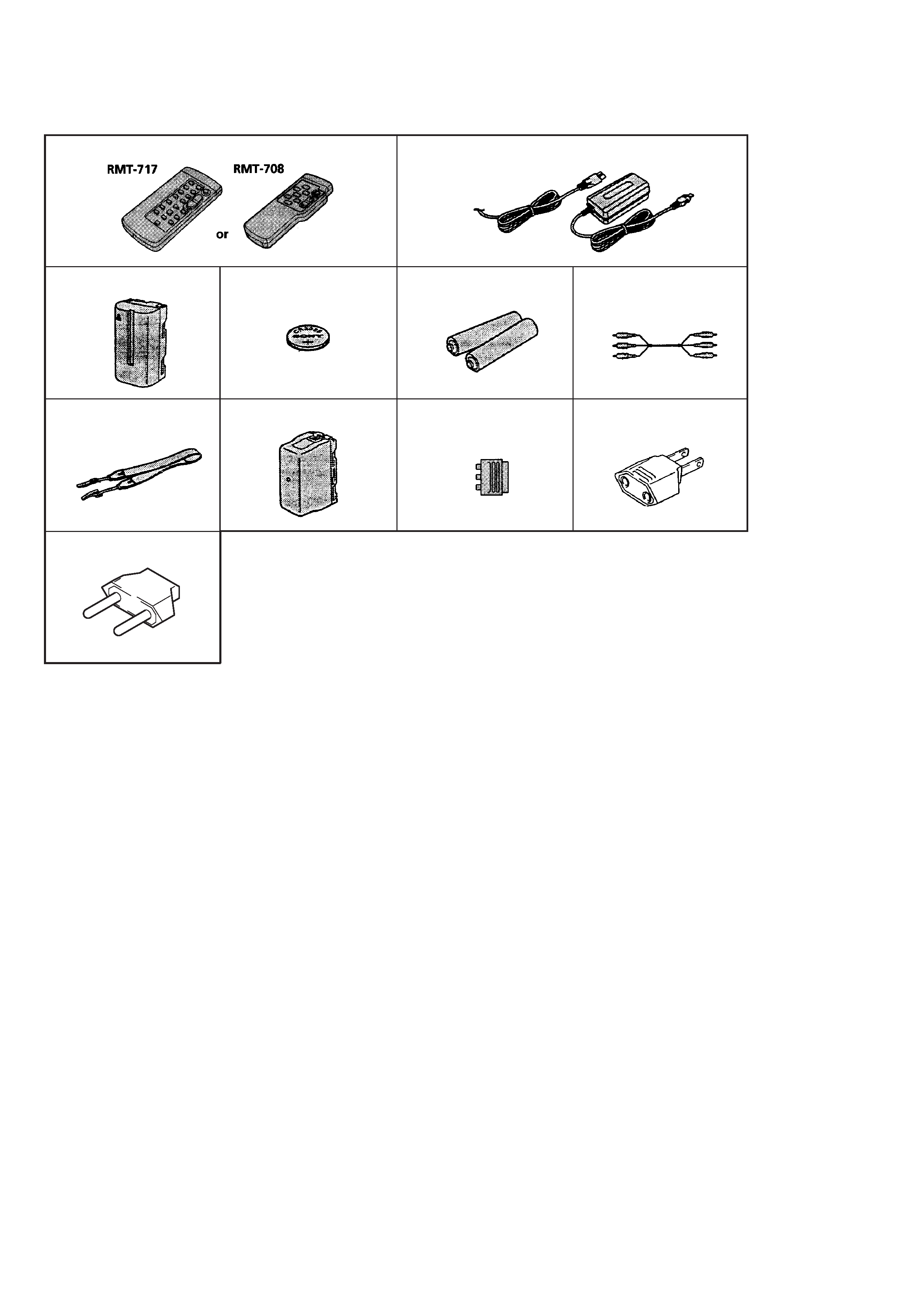
4
Supplied accessories
1 Wireless Remote Commander (1)
RMT-717 : CCD-TRV95E/TRV99/TRV99E
RMT-708 : Except CCD-TRV95E/TRV99/TRV99E
2 AC-L10A/L10B/L10C AC power adaptor
3 NP-F330 Battery pack (1)
4 CR2025 Lithium Battery (1)
The lithium battery is already installed in your camcorder.
5 Size AA (R6) battery for Remote Commander
(2)
6 A / V connecting cable (1)
7 Shoulder strap (1)
8 Battery case (1)
CCD-TRV95 : CND/TRV99
1
4
8
7
3
2
56
90
· Abbreviation
CND : Canadian Model
HK : Hong Kong Model
AUS : Australian Model
JE
: Tourist Model
!¡
9 21 pin adaptor (1)
VMC-91 : CCD-TRV95E
!º 2 pin conversion adaptor (1)
CCD-TRV89E : E, HK/TRV95 : E/TRV95PK/TRV99E : E,
HK, AUS
!¡ 2 pin conversion adaptor (1)
CCD-TRV89E : JE/TRV95 : JE/TRV99E : JE
5
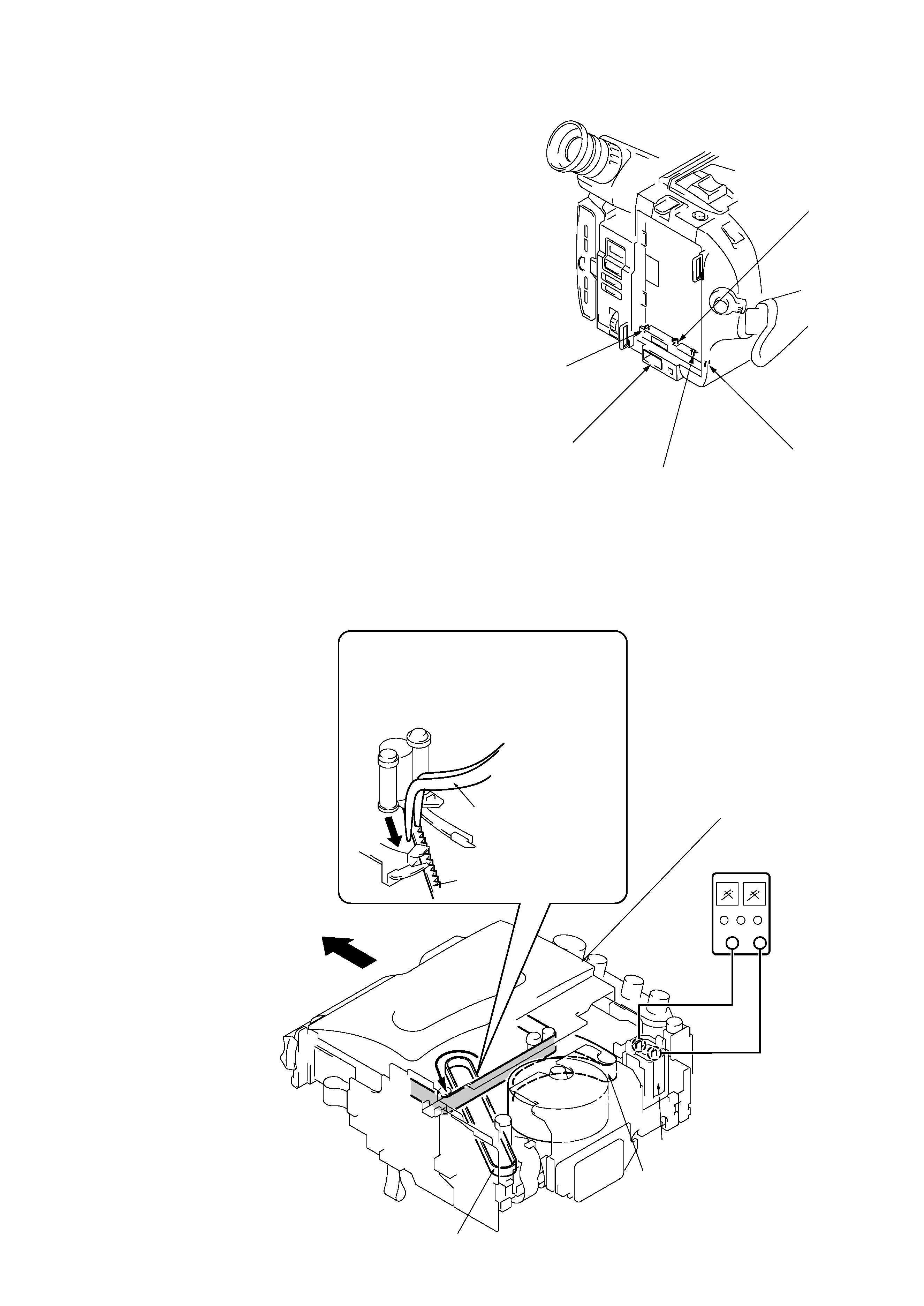
Battery terminal `
DC IN terminal
Battery SIG terminal
Battery switch
Battery terminal '
SERVICE NOTE
6
Pull the timing belt in the direction of arrow
A
with a pinsette while pressing the cassette lid
(take care not to damage) to adjust the
bending of a tape.
7
Let go your hold the cassette
lid and rise the cassette
compartment to take out a cassette.
A
Pinsette
Timing belt
Press the cassette lid not to rise the
cassette compartment
+
[DC power supply]
(+5V)
Loading motor
Adjust the bending of a tape
Timing belt
1 Refer to 2-1. to remove the front panel assembly.
2 Refer to 2-3. to remove the cabinet (R) assembly.
3 Refer to 2-10. to remove the battery panel assembly.
4 Refer to 2-10. to remove the cabinet (L) assembly.
5 Add +5V from the DC POWER SUPPLY and unload with a
pressing the cassette lid.
2. TO TAKE OUT A CASSETTE WHEN NOT EJECT (FORCE EJECT)
1. POWER SUPPLY DURING REPAIRS
In this unit, about 10 seconds after power is supplied (8.4V) to the
battery terminal using the service power cord (J-6082-223-A), the
power is shut off so that the unit cannot operate.
This following two methods are available to prevent this. Take note
of which to use during repairs.
Method 1.
Connect the servicing remote commander RM-95 (J-6082-053-B)
to the LANC jack, and set the remote commander switch to the
"ADJ" side.
Method 2.
Press the battery switch of the battery terminal using adhesive tape,
etc.
Method 3.
Use the DC IN terminal. (Use the AC power adaptor.)