SERVICE MANUAL
DIGITAL VIDEO CASSETTE RECORDER
SPECIFICATIONS
RMT-814
B700 MECHANISM
TM
Continued on next page
NTSC MODEL : DCR-TRV820/TRV820P
PAL MODEL
: DCR-TRV820E
For MECHANISM ADJUSTMENT, refer to
the "8mm Video MECHANICAL
ADJUSTMENT MANUAL
" (9-973-801-11).
Photo: DCR-TRV820E
US Model
Canadian Model
DCR-TRV820
AEP Model
UK Model
DCR-TRV820E
E Model
DCR-TRV820/TRV820E/TRV820P
Korea Model
DCR-TRV820
Australian Model
Chinese Model
DCR-TRV820E
Tourist Model
DCR-TRV820/TRV820E
DCR-TRV820/TRV820E/TRV820P
Video camera
recorder
System
Video recording system
2 rotary heads
Helical scaning system
Audio recording system
Rotary heads, PCM system
Quantization: 12 bits (Fs 32 kHz,
stereo 1, stereo 2), 16 bits
(Fs 48 kHz, stereo)
Video signal
DCR-TRV820/TRV820P :
NTSC color, EIA standards
DCR-TRV820E :
PAL colour, CCIR standards
Recommended cassette
Hi8/Digital8 video cassette
Recording/Playback time (using
120 min. Hi8 video cassette)
SP mode: 1 hour
LP mode: 1 hour and 30 minutes
Fastforward/rewind time (using
120 min. Hi8 video cassette)
Approx. 5 min.
Viewfinder
Electric Viewfinder (colour)
Image device
1/4 type CCD (Change Coupled
Device)
DCR-TRV820/TRV820P :
Approx. 460,000 pixels
(Effective: Approx. 290,000 pixels)
DCR-TRV820E :
Approx. 800,000 pixels
(Effective: Approx. 400,000 pixels)
Lens
Combined power zoom lens
Filter diameter 37 mm (1 1/2 in.)
25
× (Optical)
DCR-TRV820/TRV820E: E, AUS, CN,
JE/TRV820P :
450
× (Digital)
DCR-TRV820E: AEP, UK :
100
× (Digital)
Focal length
3.7 - 92.5 mm (5/32 - 3 3/4 in.)
When converted to a 35 mm still camera
48 - 1200 mm (1 15/16 - 47 1/4 in.)
Colour temperature
Auto
Minimum illumination
DCR-TRV820/TRV820P :
1 lux (F 1.6)
DCR-TRV820E :
3 lux (F 1.6)
0 lux (in the NightShot mode)*
* Objects unable to be seen due to the
dark can be shot with infrared
lighting.
Input/output
connectors
DCR-TRV820/TRV820P :
S video input/output
4-pin mini DIN
Luminance signal: 1 Vp-p,
75 ohms, unbalanced
Chrominance signal: 0.286 Vp-p,
75 ohms, unbalanced
Audio/Video input/output
AV MINIJACK, 1 Vp-p, 75 ohms,
unbalanced, sync negative
327 mV, (at output impedance more than
47 kilohms)
Output impedance with less than 2.2
kilohms/Stereo minijack (ø 3.5 mm)
Input impedance more than 47 kilohms
DCR-TRV820E :
S video input/output
4-pin mini DIN
Luminance signal: 1 Vp-p,
75 ohms, unbalanced
Chrominance signal: 0.3 Vp-p,
75 ohms, unbalanced
Audio/Video output
AV MINIJACK, 1 Vp-p, 75 ohms,
unbalanced, sync negative
327 mV, (at output impedance more than
47 kilohms)
Output impedance with less than 2.2
kilohms/Stereo minijack (ø 3.5 mm)
DV input/output
4-pin connector
Headphone jack
Stereo minijack (ø 3.5 mm)
LANC
/DIGITAL I/O jack
Stereo mini-minijack (ø 2.5 mm)
Transfer rate: Max 115.2 Kbps
RS-232C based
MIC jack
Stereo minijack (ø 3.5 mm)
When the machine needs to be repaired,
please refer to page 8 to discriminate the
type of LCD.
Ver 1.3 2004. 09

2
1. Check the area of your repair for unsoldered or poorly-sol-
dered connections. Check the entire board surface for solder
splashes and bridges.
2. Check the interboard wiring to ensure that no wires are
"pinched" or contact high-wattage resistors.
3. Look for unauthorized replacement parts, particularly transis-
tors, that were installed during a previous repair. Point them
out to the customer and recommend their replacement.
4. Look for parts which, though functioning, show obvious signs
of deterioration. Point them out to the customer and recom-
mend their replacement.
SAFETY CHECK-OUT
After correcting the original service problem, perform the following
safety checks before releasing the set to the customer.
5. Check the B+ voltage to see it is at the values specified.
6. Flexible Circuit Board Repairing
·
Keep the temperature of the soldering iron around 270 °C
during repairing.
·
Do not touch the soldering iron on the same conductor of
the circuit board (within 3 times).
·
Be careful not to apply force on the conductor when sol-
dering or unsoldering.
ATTENTION AU COMPOSANT AYANT RAPPORT
À LA SÉCURITÉ!
LES COMPOSANTS IDENTIFIÉS PAR UNE MARQUE 0
SUR LES DIAGRAMMES SCHÉMATIQUES ET LA LISTE
DES PIÈCES SONT CRITIQUES POUR LA SÉCURITÉ
DE FONCTIONNEMENT. NE REMPLACER CES COM-
POSANTS QUE PAR DES PIÈCES SONY DONT LES
NUMÉROS SONT DONNÉS DANS CE MANUEL OU
DANS LES SUPPLÉMENTS PUBLIÉS PAR SONY.
SAFETY-RELATED COMPONENT WARNING!!
COMPONENTS IDENTIFIED BY MARK 0 OR DOTTED
LINE WITH MARK 0 ON THE SCHEMATIC DIAGRAMS
AND IN THE PARTS LIST ARE CRITICAL TO SAFE
OPERATION. REPLACE THESE COMPONENTS WITH
SONY PARTS WHOSE PART NUMBERS APPEAR AS
SHOWN IN THIS MANUAL OR IN SUPPLEMENTS PUB-
LISHED BY SONY.
LCD screen
Picture
4.0 type
80.6
× 60.5 mm (3 1/4 × 2 1/2 in.)
Total dot number
123,200 (560
× 220)
Printer
Print method
Variable dot thermal transfer
Print resolution
254 dpi
Number of printed dots
640
× 480 (paper feed direction)
Print speed
2.54 mm (1/8 in.)/second
Size of print paper
91
× 55 mm
(3 5/8
× 2 1/4 in.)
Print area size
64
× 48 mm
(2 5/8
× 1 15/16 in.)
Number of prints per print
cartridge roll
20
Power Consumption
8 W
General
power requirements
7.2 V (battery pack)
8.4 V (AC power adaptor)
Average power consumption
(When using the battery pack)
During camera recording using
LCD
4.4 W
Viewfinder
DCR-TRV820/TRV820P :
3.0 W
DCR-TRV820E :
3.1 W
Operating temperature
0 °C to 40 °C (32 °F to 104 °F)
Storage temperature
20 °C to +60 °C (4 °F to +140 °F)
Dimensions (approx.)
112
× 121 × 218 mm
(4 1/2
× 4 7/8 × 8 5/8 in.) (w/h/d)
Mass (approx.)
1.3 kg (2 lb 13 oz)
excluding the battery pack, lithium
battery, cassette and shoulder strap
1.4 kg (3 lb 1 oz)
DCR-TRV820/TRV820P :
including the battery pack NP-F330,
lithium battery CR2025, 120 min. Hi8
cassette, and shoulder strap
DCR-TRV820E :
including the battery pack NP-F330,
lithium battery CR2025, 90 min. Hi8
cassette, and shoulder strap
AC power adaptor
Power requirements
100 - 240 V AC, 50/60 Hz
Power consumption
23 W
Output voltage
DC OUT: 8.4 V, 1.5 A in the
operating mode
Operating temperature
0 °C to 40 °C (32 °F to 104 °F)
Storage temperature
20 °C to +60 °C (4 °F to +140 °F)
Dimensions (approx.)
125
× 39 × 62 mm
(5
× 1 9/16 × 2 1/2 in.) (w/h/d)
excluding projecting parts
Mass (approx.)
280 g (9.8 oz)
excluding power cord
Battery Pack
Output voltage
DC 7.2 V
Capacity
5.0 Wh
Dimensions (approx.)
38
× 21 × 71 mm
(1 9 /16
× 1 3/16 × 2 7/8 in.) (w/h/d)
Mass (approx.)
95 g (3.4 oz)
Type
Lithium ion
"Memory Stick"
Memory
Flash memory
4 MB: MSA-4A
Operating voltage
2.7 - 3.6 V
Power consumption
Approx. 45 mA in the operating mode
Approx. 130 µA in the standby mode
Dimensions (approx.)
50
× 2.8 × 21.5 mm
(2
× 1/8 × 7/8 in.) (w/h/d)
Mass (approx.)
4 g (0.14 oz)
Design and specifications are subject to
change without notice.
3
Table for differences of function
AEP, UK
PAL
100
×
960H
CD-271
Model
Destination
Color system
Digital zoom
CCD imager
LCD type
CD board
DCR-TRV820
US, CND, E,
KR, JE
E, AUS,
CN, JE
PAL
450
×
960H
CD-271
DCR-TRV820E
· Abbreviation
AUS : Australian model
CN
: Chinese model
CND : Canadian model
JE
: Tourist model
KR
: Korea model
DCR-TRV820P
E
NTSC
450
×
720H
CD-270
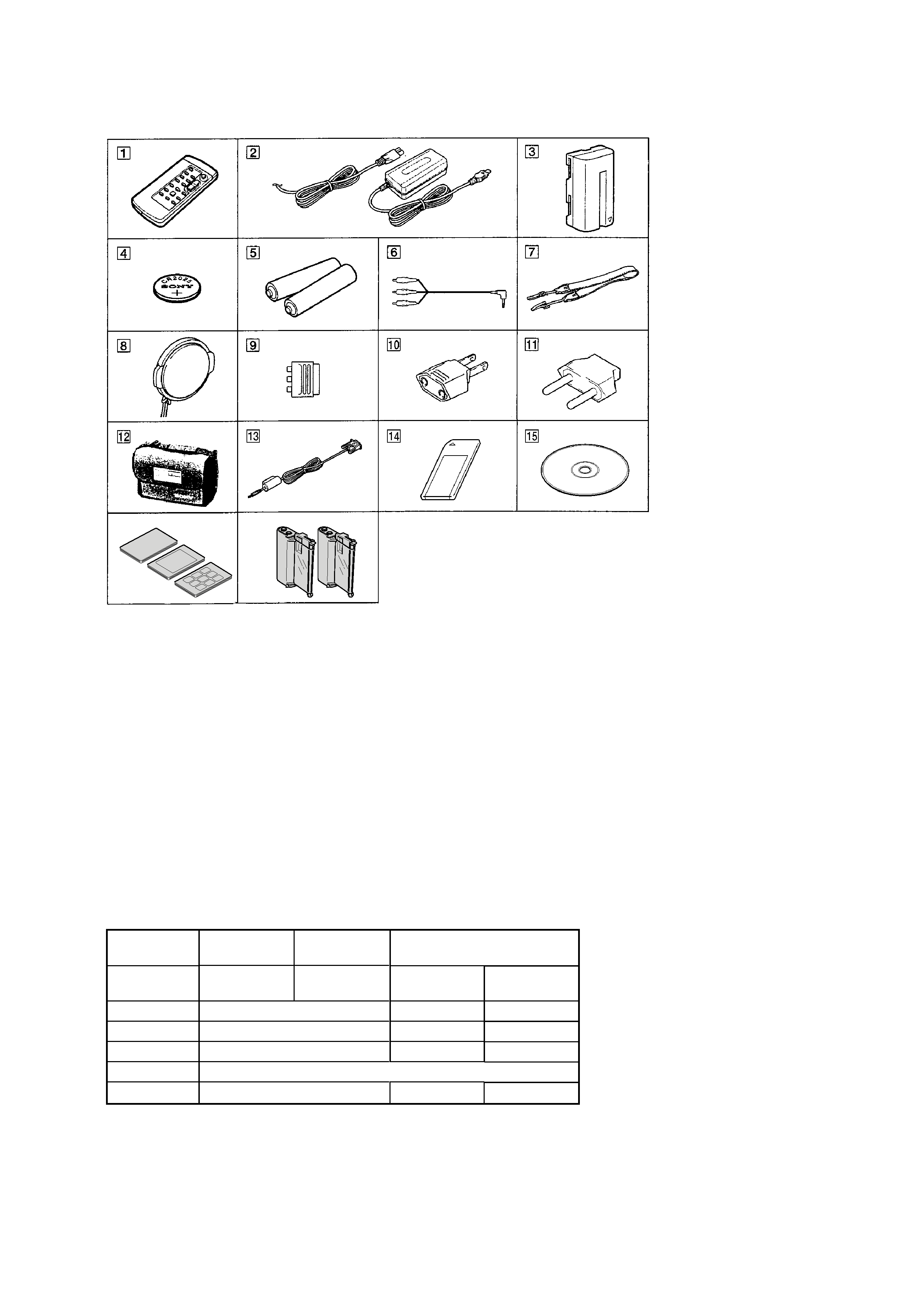
Supplied accessories
1 Wireless Remote Commander (1)
2 AC-L10A/L10B/L10C AC Power adaptor (1),
Mains lead (1)
3 NP-F330 battery pack (1)
4 CR2025 lithium battery (1)
The lithium battery is already installed in your camcorder.
5 R6 (Size AA) battery for Remote Commander (2)
6 A/V connecting cable (1)
7 Shoulder strap (1)
8 Lens cap (1)
9 21-pin adaptor (1)
DCR-TRV820E: AEP, UK
0 2-pin conversion adaptor (1)
DCR-TRV820: E/TRV820E: E/TRV820P
qa 2-pin conversion adaptor (1)
DCR-TRV820: JE/TRV820E: JE
qs Carrying bag (1)
DCR-TRV820P
qd PC serial cable (1)
qf "Memory Stick" (1)
qg Application software: PictureGear 4.1 Lite (CD ROM) (1)
qh Print paper
Standard type (20 sheets
×1),
Sticker type/Standard size (10 sheets
×1),
Sticker type/9 split size (10 sheets
×1)
qj Print cartridge (2)
qh
qj
Please refer to page 8 to discriminate the type of LCD (TYPE C or TYPE S).

4
TABLE OF CONTENTS
Section
Title
Page
Section
Title
Page
SERVICE NOTE
1.
Power Supply During Repairs .................................... 7
2.
To Take Out a Cassette
When Not Eject (Force Eject) .................................... 7
3.
Note for Repair ........................................................... 8
4.
LCD Type Check ........................................................ 8
SELF-DIAGNOSIS FUNCTION
1.
Self-diagnosis Function .............................................. 9
2.
Self-diagnosis Display ................................................ 9
3.
Service Mode Display ................................................ 9
3-1.
Display Method ........................................................... 9
3-2.
Switching of Backup No. ............................................ 9
3-3.
End of Display ............................................................ 9
4.
Self-diagnosis Code Table ......................................... 10
1.
GENERAL
Checking Supplied Accessories .......................................... 1-1
Quick Start Guide ................................................................. 1-1
Using This Manual ................................................................ 1-2
Step 1 Preparing the Power Supply ..................................... 1-2
Step 2 Inserting a Cassette .................................................. 1-4
Recording a Picture .............................................................. 1-5
Checking the Recording
END SEARCH/EDIT SEARCH/Rec Review ..................... 1-7
Playing Back a Tape ............................................................. 1-8
Viewing the Recording on TV ............................................... 1-9
Recording a Still Image on a Tape
Tape Photo Recording ....................................................... 1-10
Using the Wide Mode ........................................................... 1-11
Using the Fader Function ..................................................... 1-11
Using Special Effects
Picture Effect ..................................................................... 1-12
Using Special Effects
Digital Effect ...................................................................... 1-12
Using the PROGRAM AE Function ...................................... 1-13
Adjusting the Exposure Manually ......................................... 1-13
Focusing Manually ............................................................... 1-14
Superimposing a Title ........................................................... 1-14
Making Your Own Titles ........................................................ 1-15
Inserting a Scene ................................................................. 1-15
Playing Back a Tape with Picture Effects ............................. 1-15
Playing Back a Tape with Digital Effects .............................. 1-16
Enlarging Recorded Images
PB ZOOM .......................................................................... 1-16
Quickly Locating a Scene Using the Zero Set
Memory Function .................................................................. 1-16
Searching a Recording by Date
Date Search ....................................................................... 1-17
Searching for a Photo
Photo Search/Photo Scan ................................................. 1-17
Dubbing a Tape .................................................................... 1-18
Using with Analog Video Unit and PC
Signal Convert Function .................................................... 1-19
Recording Video or TV Programmes ................................... 1-19
Inserting a Scene from a VCR
Insert Editing ...................................................................... 1-20
Changing the Menu Settings ................................................ 1-21
Resetting the Date and Time ................................................ 1-23
Using "Memory Stick" Introduction .................................... 1-23
Recording Still Images on "Memory Stick"
Memory Photo Recording ................................................. 1-24
Superimposing a Still Image in the
"Memory Stick" on a moving Image
MEMORY MIX ................................................................... 1-26
Recording an Image from a Tape as a Still Image .............. 1-27
Copying Still Images from a Tape
Photo Save ........................................................................ 1-27
Viewing a Still Image
Memory Photo Playback ................................................... 1-28
Copying the Image Recorded on
"Memory Stick" to Tapes ....................................................... 1-29
Enlarging Still Images Recorded on "Memory Stick"s
Memory PB ZOOM ............................................................ 1-29
Playing Back Images in a Continuous Loop
SLIDE SHOW .................................................................... 1-30
Preventing Accidental Erasure
Image Protection ............................................................... 1-30
Deleting Images .................................................................... 1-31
Writing a Print Mark
PRINT MARK ..................................................................... 1-31
Using the Printer
Introduction ........................................................................ 1-32
Making Prints
Standard Print .................................................................... 1-34
Making Prints of Split Screens
Sprit Printing ...................................................................... 1-36
Digital8 System, Recording and Playback ........................... 1-36
About i. LINK ........................................................................ 1-37
Changing the Lithium Battery in Your Camcorder ............... 1-37
Troubleshooting .................................................................... 1-38
Self-diagnosis Display .......................................................... 1-39
Warning Indicators and Messages ....................................... 1-39
Using Your Camcorder Abroad ............................................ 1-40
Maintenance Information and Precautions .......................... 1-40
Identifying the Parts and Controls ........................................ 1-41
2.
DISASSEMBLY
2-1.
LCD Assembly, PD-118 Board ................................... 2-2
2-2.
VF-141 Board, VF Lens Assembly ............................. 2-3
2-3.
Front Panel Assembly ................................................ 2-4
2-4.
Cassette Lid Assembly, Cabinet (L) Assembly .......... 2-4
2-5.
Cabinet (R) Assembly ................................................ 2-5
2-6.
PC-78 Board ............................................................... 2-5
2-7.
Cabinet (L) Assembly ................................................. 2-6
2-8.
Battery Panel Assembly ............................................. 2-6
2-9.
PR-33 Board, Printer Unit .......................................... 2-6
2-10. CF-72 Board ............................................................... 2-7
2-11. Lens Block .................................................................. 2-8
2-12. SE-114 Board, Control Switch Block (FK-10000) ...... 2-8
2-13. FU-141 Board ............................................................. 2-8
2-14. VC-235 Board ............................................................. 2-8
2-15. Circuit Boards Location .............................................. 2-10
2-16. Flexible Boards Location ............................................ 2-11
3.
BLOCK DIAGRAMS
3-1.
Overall Block Diagram 1 ............................................ 3-1
3-2.
Overall Block Diagram 2 ............................................ 3-3
3-3.
Overall Block Diagram 3 ............................................ 3-5
3-4.
Overall Block Diagram 4 ............................................ 3-7
3-5.
Power Block Diagram 1 .............................................. 3-9
3-6.
Power Block Diagram 2 .............................................. 3-11
3-7.
Power Block Diagram 3 .............................................. 3-13
4.
PRINTED WIRING BOARDS AND
SCHEMATIC DIAGRAMS
4-1.
Frame Schematic Diagrams ...................................... 4-3
Frame (1) Schematic Diagram ................................... 4-3
Frame (2) Schematic Diagram ................................... 4-5
4-2.
Printed Wiring Boards and Schematic Diagrams ...... 4-7
CD-270 Printed Wiring Board and
Schematic Diagram .................................................... 4-7
CD-271 Printed Wiring Board and
Schematic Diagram .................................................... 4-9
VC-235 Printed Wiring Board .................................... 4-11

5
Section
Title
Page
Section
Title
Page
VC-235 (CAMERA PROCESSOR)
Schematic Diagram .................................................... 4-15
VC-235 (Y/C PROCESSOR)
Schematic Diagram .................................................... 4-17
VC-235 (LENS MOTOR DRIVE)
Schematic Diagram .................................................... 4-19
VC-235 (VIDEO IN/OUT) Schematic Diagram .......... 4-21
VC-235 (BASE BAND INPUT)
Schematic Diagram .................................................... 4-23
VC-235 (VIDEO/AUDIO DSP, D/A CONVERTER)
Schematic Diagram .................................................... 4-25
VC-235 (DV INTERFACE, OSD)
Schematic Diagram .................................................... 4-27
VC-235 (A/D CONVERTER, REC/PB AMP)
Schematic Diagram .................................................... 4-29
VC-235 (Hi8/Std8 PB AMP) Schematic Diagram ...... 4-31
VC-235 (HI CONTROL) Schematic Diagram ............ 4-33
VC-235 (Digital8 MECHANISM CONTROL)
Schematic Diagram .................................................... 4-35
VC-235 (CAMERA CONTROL, Hi8/Std8 MECHANISM
CONTROL) Schematic Diagram ................................ 4-37
FP-38, FP-220, FP-221, FP-249, FP-355, FP-356,
VC-235 (SERVO) Schematic Diagram ..................... 4-39
FP-249, FP-355, FP-356 Printed Wiring Boards and
VC-235 (D/A CONVERTER) Schematic Diagram ..... 4-41
VC-235 (AUDIO IN/OUT) Schematic Diagram .......... 4-43
VC-235 (DC/DC CONVERTER)
Schematic Diagram .................................................... 4-45
PC-78 (DIGITAL STILL CONTROL)
Schematic Diagram .................................................... 4-47
PC-78 (STILL PICTURE SIGNAL PROCESS)
Schematic Diagram .................................................... 4-49
PC-78 (PRINTER CONTROL) Schematic Diagram .. 4-51
PC-78 (DC/DC CONVERTER)
Schematic Diagram .................................................... 4-53
PC-78 Printed Wiring Board ....................................... 4-55
PR-33 Printed Wiring Board ....................................... 4-57
PR-33 (PRINTER DRIVE), FP-162, FP-227
Schematic Diagram .................................................... 4-59
PR-33 (DC/DC CONVERTER)
Schematic Diagram .................................................... 4-61
SE-114 Printed Wiring Board ..................................... 4-63
SE-114 Schematic Diagram ....................................... 4-65
FP-156, MI-37 Printed Wiring Boards ........................ 4-67
FP-156, MI-37 (STEREO MIC AMP)
Schematic Diagram .................................................... 4-71
MI-37 (IR TRANSMITTER) Schematic Diagram ....... 4-73
CF-72 Printed Wiring Board ....................................... 4-75
MF-10000, CF-72 Schematic Diagram ...................... 4-79
KP-009 Printed Wiring Board and
Schematic Diagram .................................................... 4-81
VF-141 Printed Wiring Board ..................................... 4-83
VF-141 Schematic Diagram ....................................... 4-85
FK-10000 Schematic Diagram ................................... 4-87
LB-62 Printed Wiring Board ....................................... 4-88
LB-62 Schematic Diagram ......................................... 4-89
PD-118 Printed Wiring Board ..................................... 4-91
PD-118 (RGB LCD DRIVER, TIMING GENERATOR),
BV-10000, PR-10000 Schematic Diagram ................ 4-95
PR-10000, PD-118 (CG LCD DRIVER, BACK LIGHT)
Schematic Diagram .................................................... 4-97
FU-141 Printed Wiring Board ..................................... 4-99
SS-10000, FU-141 Schematic Diagram .................... 4-101
4-3.
Waveforms ................................................................. 4-103
4-4.
Parts Location ............................................................ 4-107
5.
ADJUSTMENTS
1.
Before Starting Adjustment ........................................ 5-1
1-1.
Adjusting Items
when Replacing Main Parts and Boards .............. 5-2
5-1.
Camera Section Adjustment ...................................... 5-4
1-1.
Preparations Before Adjustment
(Camera Section) .................................................. 5-4
1-1-1. List of Service Tools .............................................. 5-4
1-1-2. Preparations .......................................................... 5-6
1-1-3. Precaution ............................................................. 5-8
1. Setting the Switch ................................................. 5-8
2. Order of Adjustments ............................................ 5-8
3. Subjects ................................................................. 5-8
1-2.
Initialization of 7, 8, C, D, E, F Page Data
and Modification of B Page Data .......................... 5-9
1-2-1. Initialization of 8, C, D Page Data ......................... 5-9
1. Initializing the 8, C, D Page Data .......................... 5-9
2. Modification of 8, C, D Page Data ........................ 5-9
3. 8 Page Table ......................................................... 5-9
4. C Page Table ......................................................... 5-10
5. D Page Table ......................................................... 5-11
1-2-2. Initialization of 7, E, F Page Data ......................... 5-12
1. Initializing the 7, E, F Page Data .......................... 5-12
2. Modification of 7, E, F Page Data ......................... 5-12
3. 7 Page Table ......................................................... 5-12
4. E Page Table ......................................................... 5-13
5. F Page Table ......................................................... 5-14
1-2-3. Modification of B Page Data ................................. 5-15
1. Modification of B Page Data ................................. 5-15
2. B Page Table ......................................................... 5-15
1-3.
Camera System Adjustments ............................... 5-15
1. HALL Adjustment ................................................... 5-15
2. Flange Back Adjustment
(Using the Minipattern Box) .................................. 5-16
3. Flange Back Adjustment
(Using Flange Back Adjustment Chart Subject
More Than 500 m Away) ....................................... 5-17
3-1. Flange Back Adjustment (1) .................................. 5-17
3-2. Flange Back Adjustment (2) .................................. 5-17
4. Flange Back Check ............................................... 5-18
5. Optical Axis Adjustment ........................................ 5-19
6. Picture Frame Setting ........................................... 5-20
7. Color Reproduction Adjustment ............................ 5-21
8. AWB & LV Standard Data Input ............................ 5-22
9. Auto White Balance Adjustment ........................... 5-22
10. White Balance Check ............................................ 5-23
11. Angular Velocity Sensor Sensitivity Data Preset and
SteadyShot Check ................................................ 5-24
1-4.
Color Electronic Viewfinder
System Adjustments .............................................. 5-25
1. EVF Initial Data Input (1) ...................................... 5-25
2. EVF Initial Data Input (2) ...................................... 5-26
3. VCO Adjustment (VF-141 Board) ......................... 5-26
4. RGB AMP Adjustment (VF-141 Board) ................. 5-27
5. Contrast Adjustment (VF-141 Board) ................... 5-27
6. Backlight Consumption Current Adjustment
(VF-141 Board) ..................................................... 5-28
7. White Balance Adjustment (VF-141 Board) .......... 5-28
1-5.
LCD System Adjustments ..................................... 5-29
1. LCD Initial Data Input (1) ...................................... 5-29
2. LCD Initial Data Input (2) ...................................... 5-30
3. VCO Adjustment (PD-118 Board) ......................... 5-30
4. RGB AMP Adjustment (PD-118 Board) ................. 5-31
5. Contrast Adjustment (PD-118 Board) ................... 5-31
6. COM AMP Adjustment (PD-118 Board) ................ 5-32
7. V-COM Adjustment (PD-118 Board) ..................... 5-32
8. White Balance Adjustment
(PD-118 Board) ..................................................... 5-33
5-2.
Mechanism Section Adjustment ................................. 5-34
2-1.
Hi8/Standard 8 mm Mode ..................................... 5-34
2-1-1. How to Enter Playback Mode Without Cassette .. 5-34
2-1-2. Tape Path Adjustment ........................................... 5-34
1. Preparations for Adjustment ................................. 5-34
2-2.
Digital8 Mode ........................................................ 5-35
2-2-1. How to Enter Record Mode Without Cassette ...... 5-35
2-2-2. How to Enter Playback Mode Without Cassette .. 5-35
2-2-3. Overall Tape Path Check ...................................... 5-35
1. Recording of the Tape Path Check Signal ............ 5-35
2. Tape Path Check ................................................... 5-35
5-3.
Video Section Adjustment .......................................... 5-36
3-1.
Preparations Before Adjustments ......................... 5-36