-- 1 --
MICROFILM
SERVICE MANUAL
US Model
Canadian Model
E Model
Tourist Model
DCR-TRV7
AEP Model
UK Model
E Model
Tourist Model
DCR-TRV7E
For MECHANISM ADJUSTMENTS, refer to the
"DV MECHANICAL ADJUSTMENT MANUAL I"
(9-973-815-11).
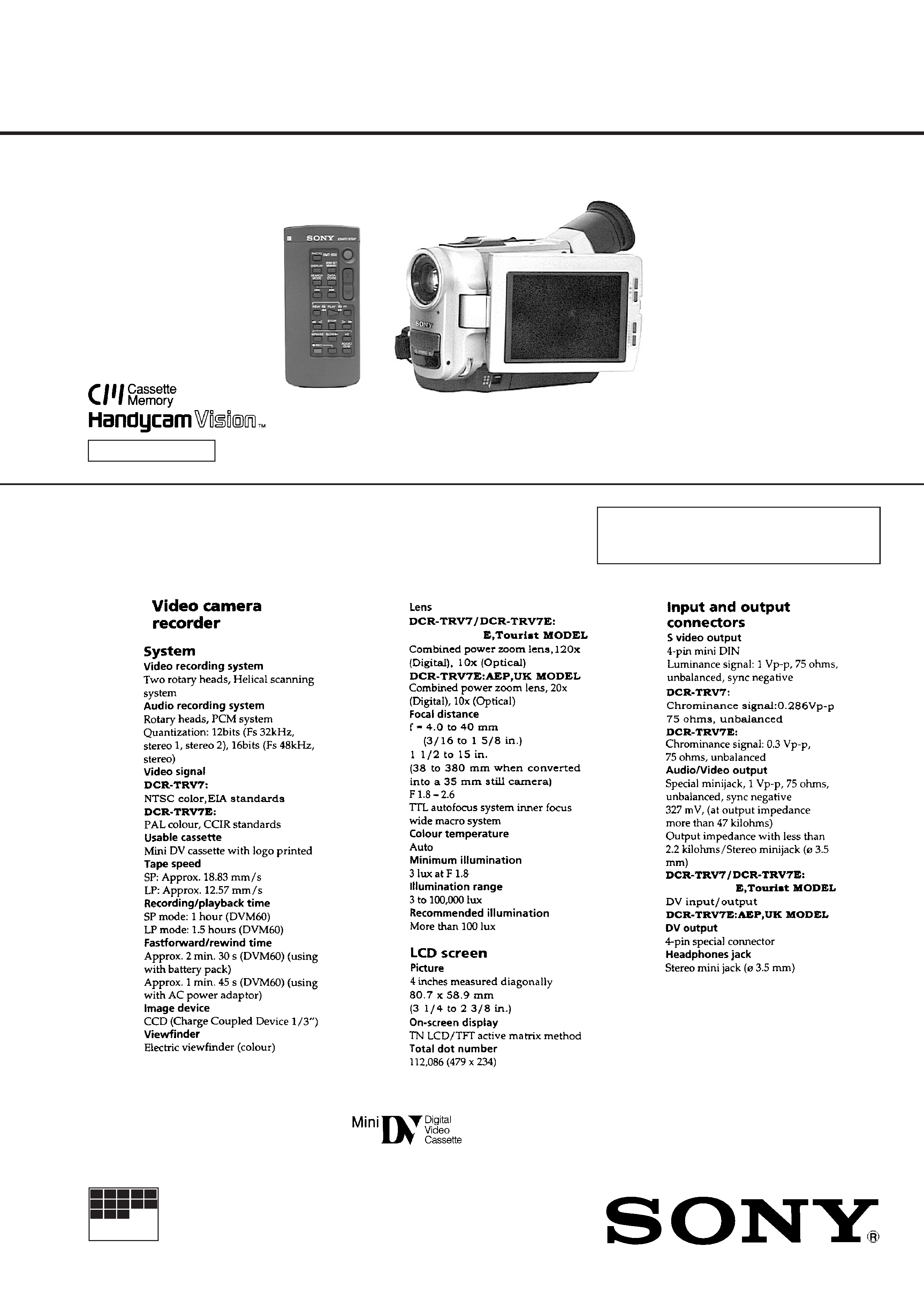
RMT-808/809
Photo : DCR-TRV7
: RMT-808
DIGITAL VIDEO CAMERA RECORDER
SPECIFICATIONS
DCR-TRV7/TRV7E
D MECHANISM
NTSC : DCR-TRV7
PAL
: DCR-TRV7E
-- Continued on next page --
-- 2 --
ATTENTION AU COMPOSANT AYANT RAPPORT
À LA SÉCURITÉ!!
LES COMPOSANTS IDENTIFIÉS PAR UNE MARQUE ! SUR
LES DIAGRAMMES SCHÉMATIQUES ET LA LISTE DES
PIÈCES SONT CRITIQUES POUR LA SÉCURITÉ DE
FONCTIONNEMENT. NE REMPLACER CES COMPOSANTS
QUE PAR DES PIÈCES SONY DONT LES NUMÉROS SONT
DONNÉS DANS CE MANUEL OU DANS LES SUPPLÉMENTS
PUBLIÉS PAR SONY.
SAFETY-RELATED COMPONENT WARNING !!
COMPONENTS IDENTIFIED BY MARK ! OR DOTTED LINE
WITH MARK ! ON THE SCHEMATIC DIAGRAMS AND IN THE
PARTS LIST ARE CRITICAL TO SAFE OPERATION. REPLACE
THESE COMPONENTS WITH SONY PARTS WHOSE PART
NUMBERS APPEAR AS SHOWN IN THIS MANUAL OR IN SUP-
PLEMENTS PUBLISHED BY SONY.
1.
Check the area of your repair for unsoldered or poorly-soldered
connections. Check the entire board surface for solder splashes
and bridges.
2.
Check the interboard wiring to ensure that no wires are
"pinched" or contact high-wattage resistors.
3.
Look for unauthorized replacement parts, particularly
transistors, that were installed during a previous repair. Point
them out to the customer and recommend their replacement.
4.
Look for parts which, though functioning, show obvious signs
of deterioration. Point them out to the customer and
recommend their replacement.
5.
Check the B+ voltage to see it is at the values specified.
6.
Flexible Circuit board Repairing
·
Keep the temperature of the soldering iron around 270°C
during repairing.
·
Do not touch the soldering iron on the same conductor of
the circuit board (within 3 times).
·
Be careful not to apply force on the conductor when
soldering or unsoldering.
SAFETY CHECK-OUT
After correcting the original service problem, perform the following
safety checks before releasing the set to the customer:
-- 3 --
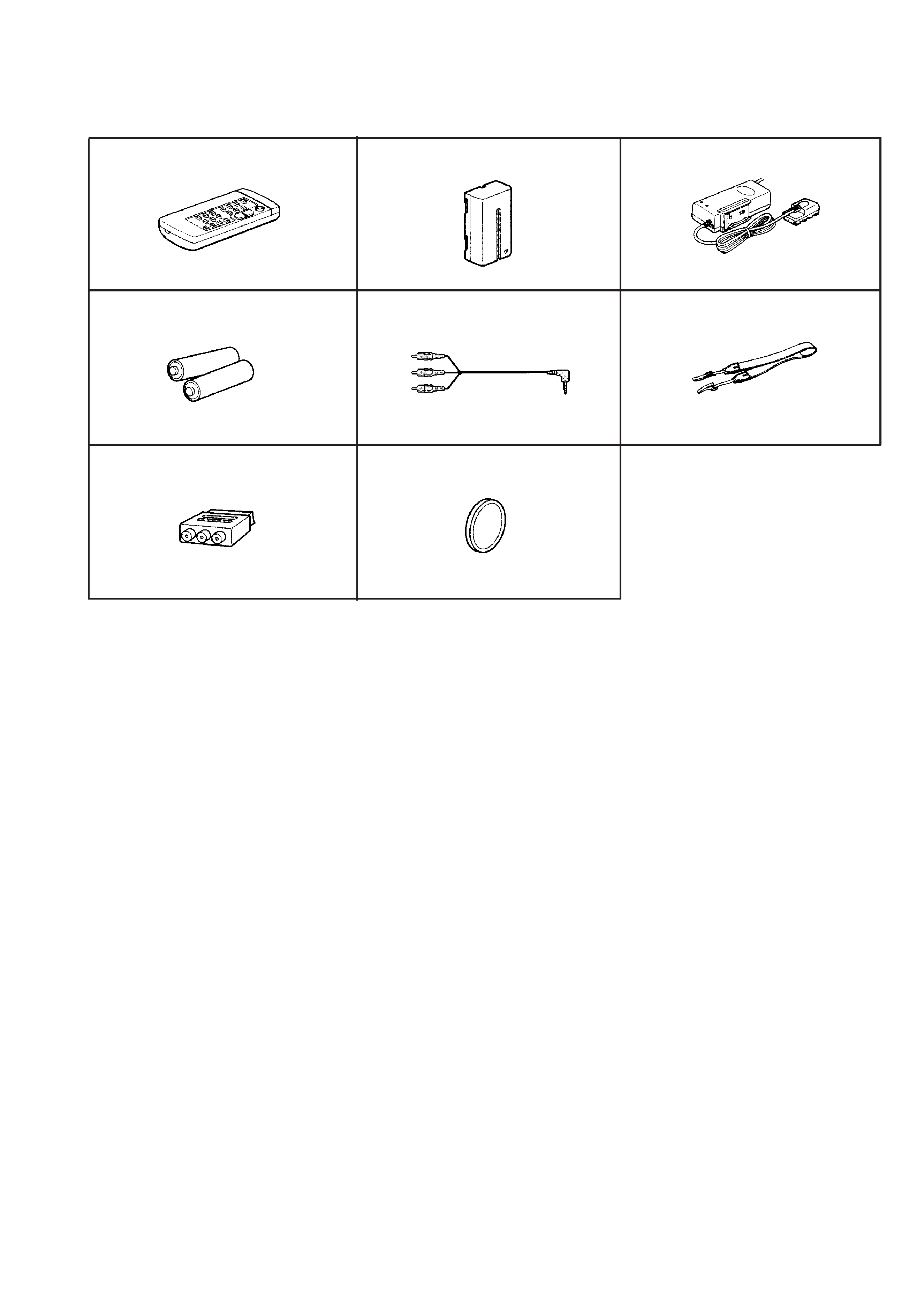
Supplied Accessories
12
3
4
5
6
78
1 Wireless Remote Commander (1)
RMT-808 ; DCR-TRV7 / TRV7E : E, Tourist
RMT-809 ; DCR-TRV7E : AEP, UK
2 NP-F530 battery pack (1)
3 AC power adaptor (1)
AC-V316A ; DCR-TRV7 : Tourist
DCR-TRV7E : E, Tourist
AC-V326
; DCR-TRV7 : US, Canadian, E
DCR-TRV7E : AEP, UK
4 R6 (size AA) battery for remote Commander (2)
5 A/V connecting cable (1)
6 Shoulder strap (1)
7 21-pin adaptor (1)
DCR-TRV7 : Tourist
DCR-TRV7E : E, Tourist
8 Lens cap (1)
-- 4 --
SERVICE NOTE
1. POWER SUPPLY DURING REPAIRS
In this unit, about 25 seconds after power is supplied (8.4V) to the
battery terminal using the service power cord (J-6082-223-A), the
power is shut off so that the unit cannot operate.
This following two methods are available to prevent this. Take note of
which to use during repairs.
Method 1.
Connect the servicing remote commander RM-95 (J-6082-053-B) to
the LANC jack, and set the remote commander switch to the "ADJ"
side.
Method 2.
Press the following battery switch using adhesive tape, etc.
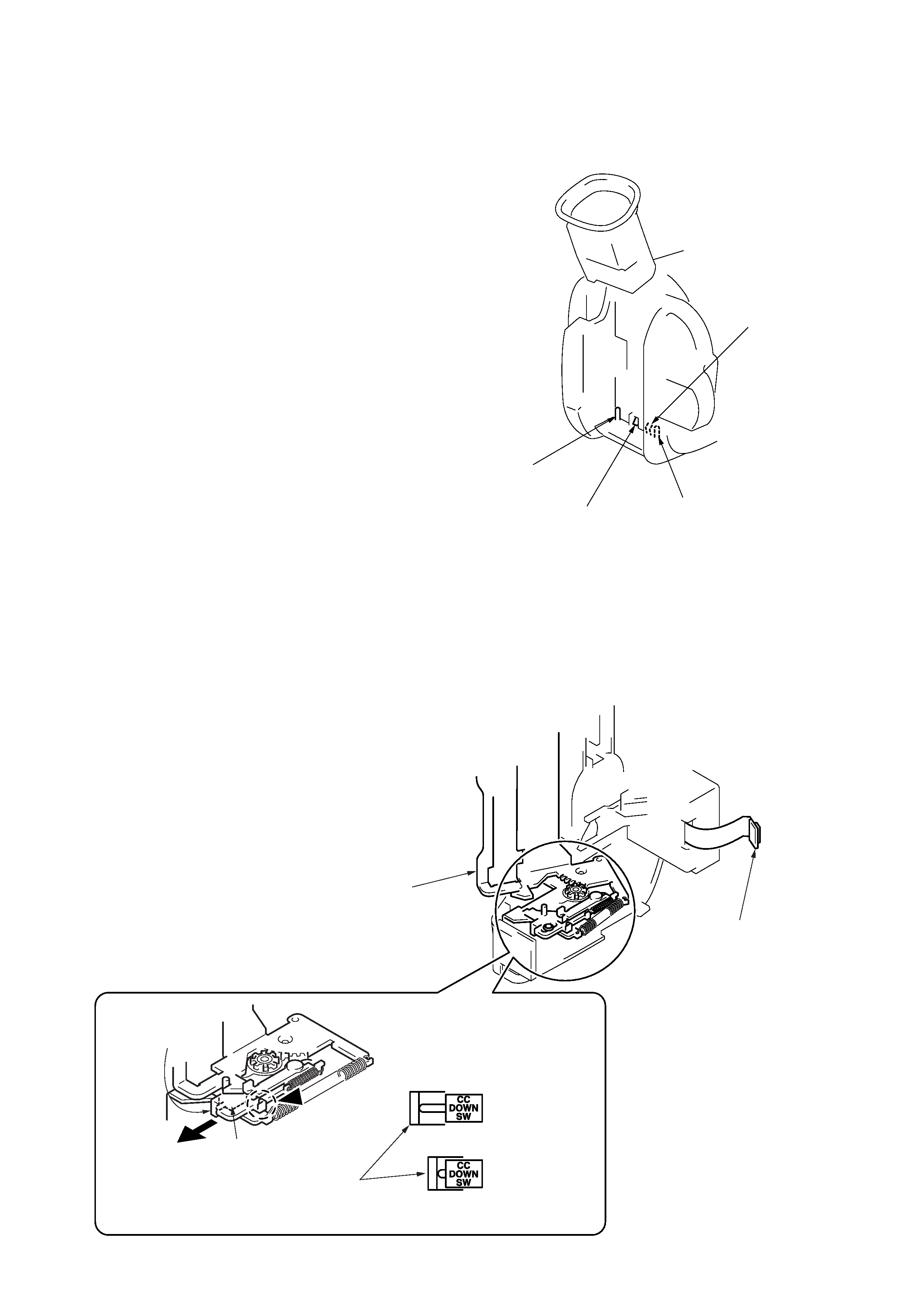
2. EJECTING WITH THE CABINET (L) ASSEMBLY
REMOVED
·
Refer to "2. DISASSEMBLY", and supply power with the cabinet
(L) assembly removed (however leaved the flexible board
connecting the cabinet (L) assembly and CB-58 board connected).
·
Ejecting:
Operate the slider, open the CS assembly (Cassette lid), turn
OFF the CC down switch, and press the Eject button again.
·
Loading:
Close the CS assembly (Cassette lid).
(Turn ON the CC down switch)
Battery terminal `
Battery terminal '
Connect to CB-58 board.
CS assembly
(Cassette lid)
CC down switch
OFF : Eject
ON : Loading
Slider
Slider
Push the ( section of slider to open the CS assembly (Cassette lid).
(CC down switch : OFF)
Battery switch
Battery SIG terminal
-- 5 --
1. Self-diagnosis Function
When problems occur while the unit is operating, the self-diagnosis
function starts working, and displays on the viewfinder what to do.
This function consists of two display; self-diagnosis display and
service mode display.
Details of the self-diagnosis functions are provided in the Instruction
manual.
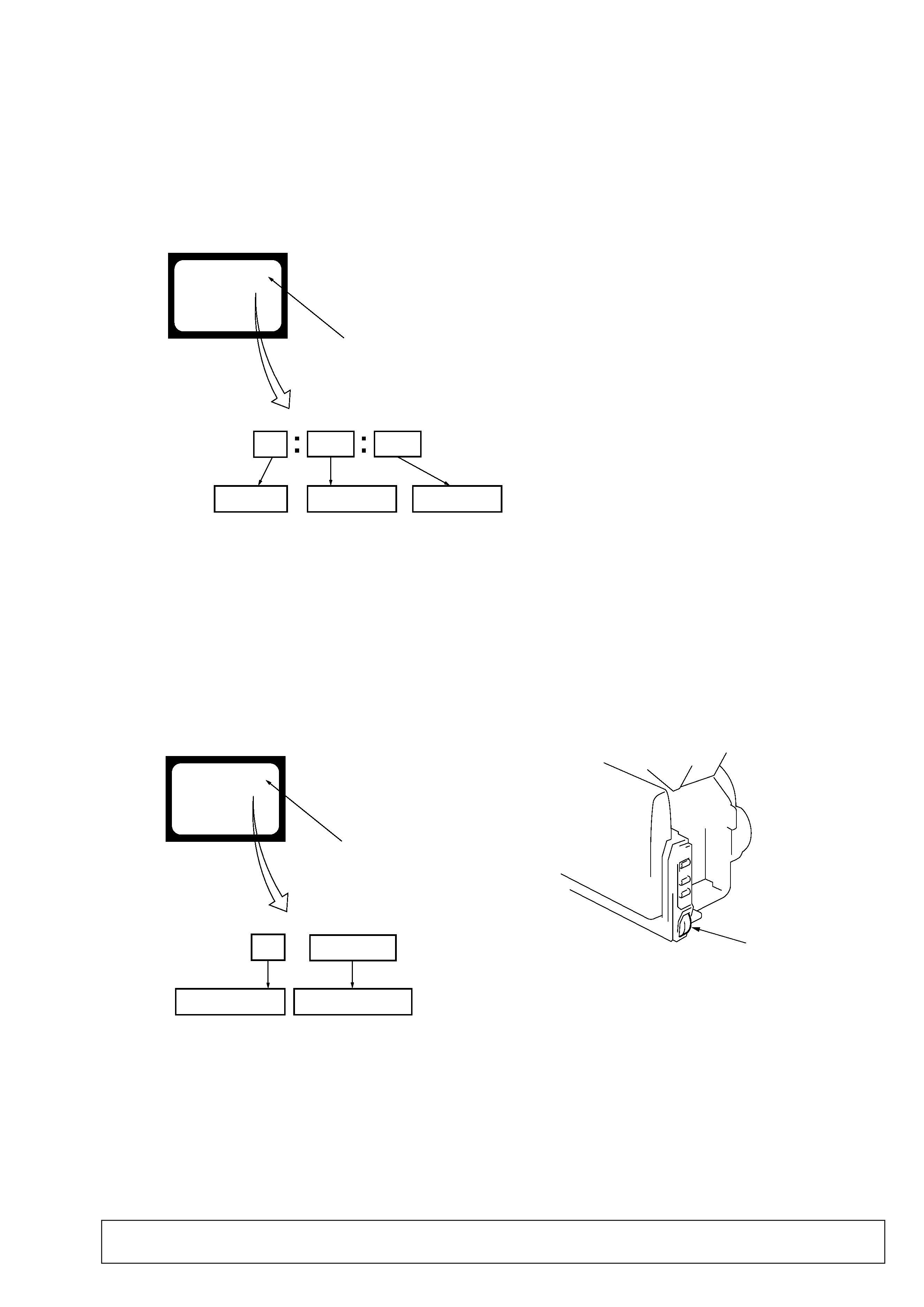
2. Self-diagnosis display
When problems occur while the unit is operating, the counter of the
viewfinder shows a 4-digit display consisting of an alphabet and
numbers, which blinks at 3.2 Hz. This 5-character display indicates
the "repaired by:", "block" in which the problem occurred, and
"detailed code" of the problem.
[3]
C : 3 1 : 1 1
SELF-DIAGNOSIS FUNCTION
3-2. Switching of Backup No.
By rotating the control dial, past self-diagnosis codes will be shown in order. The backup No. in the [] indicates the order in which the problem
occurred. (If the number of problems which occurred is less than 6, only the number of problems which occurred will be shown.)
[1] : Occurred first time
[4] : Occurred fourth time
[2] : Occurred second time
[5] : Occurred fifth time
[3] : Occurred third time
[6] : Occurred the last time
3-3. End of Display
Turning OFF the power supply will end the service mode display.
Note: The self-diagnosis display data will be backed up by the coin-type lithium battery. When this coin-type lithium battery is disconnected,
the self-diagnosis data will be lost by initialization.
1 1
3 1
C
Viewfinder
Blinks at 3.2 Hz
Lights up
Backup No.
Viewfinder
self-diagnosis codes
Order of previous errors
3. Service Mode Display
The service mode display shows up to six self-diagnosis codes shown in the past.
3-1. Display Method
While pressing the "STOP" key, set the switch from OFF to "CAMERA" or "VTR or PLAYER", and continue pressing the "STOP" key for
5 seconds continuously. The service mode will be displayed, and the counter will show the backup No. and the 5-character self-diagnosis
codes.
Repaired by:
Block
Detailed Code
Refer to page 6
Self-diagnosis Code Table.
C : Corrected by customer
H : Corrected by dealer
E : Corrected by service
engineer
Indicates the appropriate
step to be taken.
E.g.
31 .... Reload the tape.
32 .... Turn on power again.
Control dial
C : 3 1 : 1 1
[3] C : 3 1 : 1 1