DCR-TRV5/TRV5E
RMT-808/809
Canadian Model
DCR-TRV5
AEP Model
UK Model
Hong Kong Model
DCR-TRV5E
E Model
Tourist Model
DCR-TRV5/TRV5E
SERVICE MANUAL
DIGITAL VIDEO CAMERA RECORDER
MICROFILM
C MECHANISM
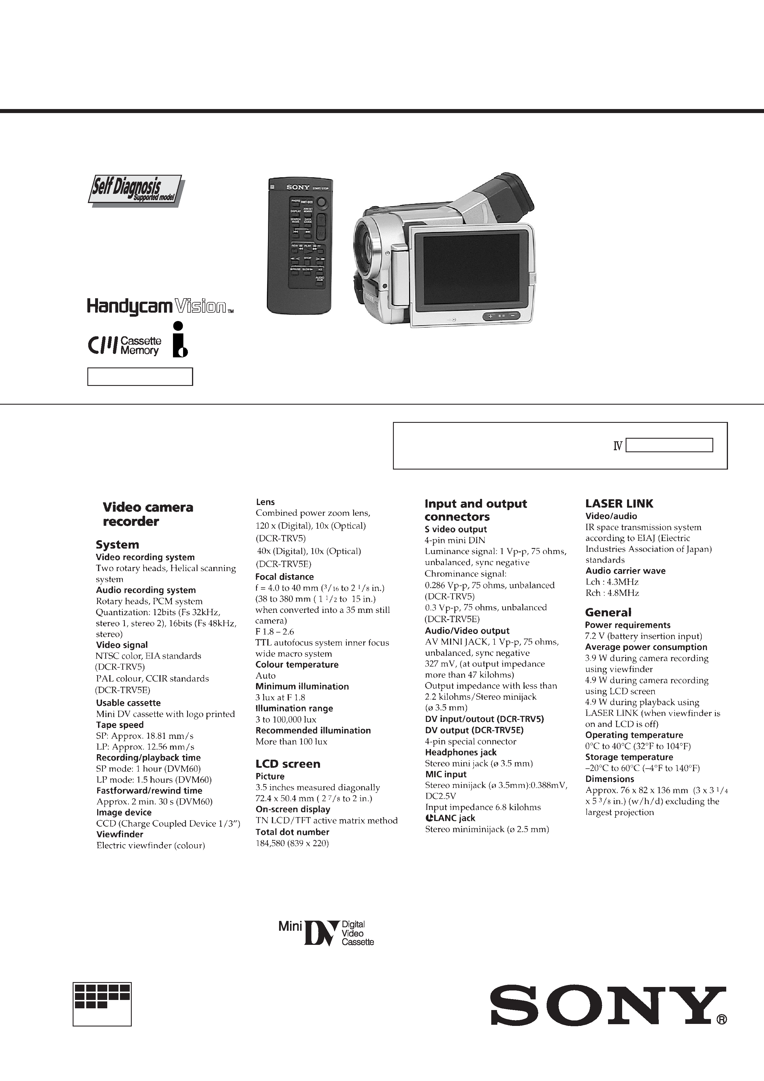
Photo: DCR-TRV5E
RMT-809
For MECHANISM ADJUSTMENTS, refer to the "DV
MECHANICAL ADJUSTMENT MANUAL
C MECHANISM "
(9-974-050-11)
NTSC model: DCR-TRV5
PAL model:
DCR-TRV5E
SPECIFICATIONS
-- Continued on next page --
-- 2 --
SAFETY-RELATED COMPONENT WARNING!!
COMPONENTS IDENTIFIED BY MARK
! OR DOTTED LINE WITH
MARK
! ON THE SCHEMATIC DIAGRAMS AND IN THE PARTS
LIST ARE CRITICAL TO SAFE OPERATION. REPLACE THESE
COMPONENTS WITH SONY PARTS WHOSE PART NUMBERS
APPEAR AS SHOWN IN THIS MANUAL OR IN SUPPLEMENTS
PUBLISHED BY SONY.
ATTENTION AU COMPOSANT AYANT RAPPORT
À LA SÉCURITÉ!
LES COMPOSANTS IDENTIFÉS PAR UNE MARQUE
! SUR LES
DIAGRAMMES SCHÉMATIQUES ET LA LISTE DES PIÈCES SONT
CRITIQUES POUR LA SÉCURITÉ DE FONCTIONNEMENT. NE
REMPLACER CES COMPOSANTS QUE PAR DES PIÈSES SONY
DONT LES NUMÉROS SONT DONNÉS DANS CE MANUEL OU
DANS LES SUPPÉMENTS PUBLIÉS PAR SONY.
1.
Check the area of your repair for unsoldered or poorly-soldered
connections. Check the entire board surface for solder splashes
and bridges.
2.
Check the interboard wiring to ensure that no wires are
"pinched" or contact high-wattage resistors.
3.
Look for unauthorized replacement parts, particularly
transistors, that were installed during a previous repair. Point
them out to the customer and recommend their replacement.
4.
Look for parts which, through functioning, show obvious signs
of deterioration. Point them out to the customer and
recommend their replacement.
5.
Check the B+ voltage to see it is at the values specified.
6.
Flexible Circuit Board Repairing
· Keep the temperature of the soldering iron around 270°C
during repairing.
· Do not touch the soldering iron on the same conductor of the
circuit board (within 3 times).
· Be careful not to apply force on the conductor when soldering
or unsoldering.
SAFETY CHECK-OUT
After correcting the original service problem, perform the following
safety checks before releasing the set to the customer.
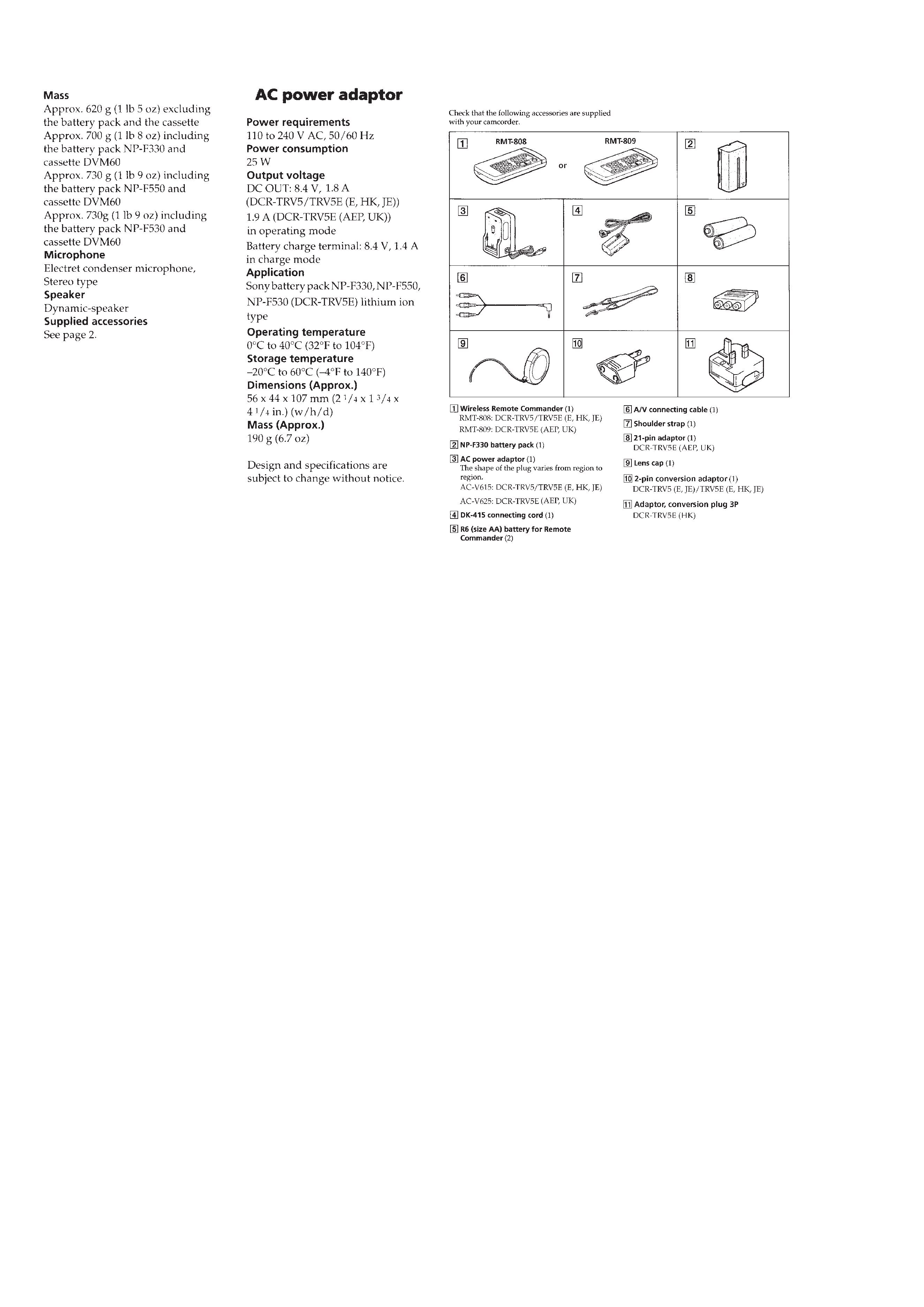
· Supplied accessories
· Abbreviation
HK:
Hong Kong model
JE:
Tourist model
CND: Canadian model

-- 3 --
TABLE OF CONTENTS
SERVICE NOTE
1.
Power Supply During Repairs ............................................ 6
2.
How to Take a Cassette Out When the Main Power Cannot
Be Turned On ..................................................................... 6
SELF-DIAGNOSIS FUNCTION
1.
Self-Diagnosis Function ..................................................... 7
2.
Self-Diagnosis Display ....................................................... 7
3.
Service Mode Display ........................................................ 7
3-1.
Display Method .................................................................. 7
3-2.
Switching of Backup No. ................................................... 7
3-3.
End of Display .................................................................... 7
4.
Self-Diagnosis Code Table ................................................. 8
1.
GENERAL
Before you begin
Using this manual .................................................................. 1-1
Checking supplied accessories .............................................. 1-1
Getting started
Charging and installing the battery pack ............................... 1-1
Inserting a cassette ................................................................. 1-2
Basic operations
Camera recording ................................................................... 1-3
Hints for better shooting ........................................................ 1-5
Playing back a tape ................................................................ 1-6
Searching for the end of the picture ....................................... 1-6
Advanced operations
Using alternative power sources ............................................ 1-7
Changing the mode settings ................................................... 1-7
Shooting with backlighting .................................................... 1-8
Using the FADER function .................................................... 1-9
Photo recording ...................................................................... 1-9
Using the wide mode function ............................................. 1-10
Using the PROGRAM AE function ..................................... 1-10
Focusing manually ............................................................... 1-11
Enjoying picture effect ......................................................... 1-11
Adjusting the exposure ........................................................ 1-12
Superimposing a title ........................................................... 1-12
Making a custom title .......................................................... 1-13
Labeling a cassette ............................................................... 1-14
Releasing the STEADYSHOT function .............................. 1-14
Watching on a TV screen ..................................................... 1-15
Searching the boundaries of recorded tape with
date - date search ................................................................. 1-16
Searching the boundaries of recorded tape with
title - title search .................................................................. 1-16
Searching for a photo - photo search/photo scan ................. 1-17
Returning to a pre-registered position ................................. 1-18
Displaying recording data - data code function ................... 1-18
Editing onto another tape ..................................................... 1-19
Audio dubbing ..................................................................... 1-19
Additional information
Usable cassette and playback modes ................................... 1-20
Charging the vanadium-lithium battery in the camcorder ... 1-21
Resetting the date and time .................................................. 1-21
Tips for using the battery pack ............................................ 1-22
Maintenance information and precautions ........................... 1-23
Using your camcorder abroad .............................................. 1-24
Trouble check ...................................................................... 1-25
Self-diagnosis function ........................................................ 1-26
Identifying the parts ............................................................. 1-26
Warning indicators ............................................................... 1-29
2.
DISASSEMBLY
2-1.
Removal of F Panel Assembly, MA-330 Board, FP-691
Board and FP-695 Board ................................................. 2-1
2-2.
Removal of Rear Cover Assembly, FP-694 Board and
Control Switch Block (FK4680, PS4680) ....................... 2-2
2-3.
Removal of Mechanism Chassis Block ........................... 2-2
2-4.
Removal of VC-207 Board, Zoom Lens,
AU-204 Board and DD-110 Board .................................. 2-3
2-5.
Removal of EVF Block ................................................... 2-3
2-6.
Removal of CD-193 Board .............................................. 2-4
2-7.
Removal of LCD Block ................................................... 2-5
2-8.
Service Position (Adjustment, Check, or/and Voltage
Measurement Mainly) ..................................................... 2-6
2-9.
Circuit Boards Location .................................................. 2-7
3.
BLOCK DIAGRAMS
3-1.
Overall Block Diagram (1) .............................................. 3-1
3-2.
Overall Block Diagram (2) .............................................. 3-5
3-3.
Power Block Diagram ..................................................... 3-9
4.
PRINTED WIRING BOARDS AND
SCHEMATIC DIAGRAMS
4-1.
Frame Schematic Diagram .............................................. 4-1
4-2.
Printed Wiring Boards and Schematic Diagrams ............ 4-5
· CD-193 (CCD Imager) Printed Wiring Board .............. 4-7
· CD-193 (CCD Imager) Schematic Diagram ................. 4-9
· VC-207 (Camera Process, Focus/Zoom/Iris Drive,
Video Out, REC/PB Process, RF Interface, RGB Decoder,
DV Signal Process, Blocking, ECC. TBC. CHCD,
Audio Signal Process, Audio Display, Mode Control,
EVR/Audio, Mecha Con/Servo)
Printed Wiring Board .................................... 4-12
· VC-207 (Camera Process)(1/15)
Schematic Diagram ....................................... 4-20
· VC-207 (Focus/Zoom/Iris Drive)(2/15)
Schematic Diagram ....................................... 4-23
· VC-207 (Video Out)(3/15)
Schematic Diagram ....................................... 4-26
· VC-207 (REC/PB Process)(4/15)
Schematic Diagram ....................................... 4-29
· VC-207 (RF Interface)(5/15)
Schematic Diagram ....................................... 4-35
· VC-207 (RGB Decoder)(6/15)
Schematic Diagram ....................................... 4-37
· VC-207 (DV Signal Process)(7/15)
Schematic Diagram ....................................... 4-40
· VC-207 (Blocking)(8/15)
Schematic Diagram ....................................... 4-43
· VC-207 (ECC. TBC. CHCD)(9/15)
Schematic Diagram ....................................... 4-48
· VC-207 (Audio Signal Process)(10/15)
Schematic Diagram ....................................... 4-51
· VC-207 (Audio Display)(11/15)
Schematic Diagram ....................................... 4-54
· VC-207 (Mode Control)(12/15)
Schematic Diagram ....................................... 4-57
· VC-207 (EVR/Audio)(13/15),
FP-691 (AV jack)
Schematic Diagrams ..................................... 4-60
· VC-207 (Mecha Con/Servo)(14/15)
Schematic Diagram ....................................... 4-63
· VC-207 (Mode Control)(15/15)
Schematic Diagram ....................................... 4-67
· LI-65 (Battery),
FP-594 (Loading Motor, Sensors, Switches)
Printed Wiring Boards ................................... 4-71
· AU-204 (Audio Processor) Printed Wiring Board ...... 4-73
· AU-204 (Audio Processor) Schematic Diagram ......... 4-75
· MA-330 (Audio Process & IR Transmmiter)
Printed Wiring Board .................................... 4-79

-- 4 --
· MA-330 (Audio Process & IR Transmmiter)
Schematic Diagram ....................................... 4-81
· PD-100 (RGB Decoder, Timming Generator,
Back Light Generator)
Printed Wiring Board .................................... 4-83
· PD-100 (RGB Decoder)(1/3)
Schematic Diagram ....................................... 4-85
· PD-100 (Timming Generator)(2/3)
Schematic Diagram ....................................... 4-87
· PD-100 (Back Light Generator)(3/3)
Schematic Diagram ....................................... 4-89
· VF-124 (Color EVF) Printed Wiring Board ............... 4-91
· VF-124 (Color EVF) Schematic Diagram .................. 4-93
· DD-110 (Drum/Capstan Pwm Drive)
Schematic Diagram ....................................... 4-98
· DD-110 (Drum/Capstan Pwm Drive)
Printed Wiring Board .................................. 4-101
5.
ADJUSTMENTS
5-1.
Camera Section Adjustment ............................................ 5-1
1-1.
Preparations before Adjustment (Camera Section) ......... 5-1
1-1-1. List of Service Tools ........................................................ 5-1
1-1-2. Preparations .................................................................... 5-2
1-1-3. Precaution ........................................................................ 5-4
1.
Setting the Switch ............................................................ 5-4
2.
Order of Adjustments ...................................................... 5-4
3.
Subjects ........................................................................... 5-4
1-2.
Initialization of F Page Data ............................................ 5-5
1.
Initializing the F Page Data ............................................. 5-5
2.
Modification of F Page Data ........................................... 5-5
3.
F Page Table .................................................................... 5-5
1-3.
Camera System Adjustments ........................................... 5-8
1.
GUM-PLL Adjustment (VC-207 board) ......................... 5-8
2.
36MHz Origin Oscillation Adjustment
(VC-207 board) ............................................................... 5-8
3.
Zoom Key Center Adjustment (VC-207 board) .............. 5-8
4.
HALL Adjustment ........................................................... 5-9
5.
Flange Back Adjustment ............................................... 5-10
5-1.
Flange Back Adjustment (1) .......................................... 5-10
5-2.
Flange Back Adjustment (2) .......................................... 5-10
6.
Flange Back Check ........................................................ 5-11
7.
Picture Frame Setting .................................................... 5-11
8.
Color Reproduction Adjustment .................................... 5-12
9.
IRIS IN/OUT Adjustment ............................................. 5-13
10.
MAX GAIN Adjustment ............................................... 5-14
11.
Auto White Balance Standard Data Input ..................... 5-14
12.
Auto White Balance Adjustment ................................... 5-15
13.
White Balance Check .................................................... 5-15
14.
Angular Velocity Sensor Sensitivity Adjustment .......... 5-16
1-4.
Color Electronic Viewfinder System Adjustment .......... 5-17
1.
EVF Initial Data Input ................................................... 5-17
2.
VCO Adjustment (VF-124 board) ................................. 5-18
3.
Bright Adjustment (VF-124 board) ............................... 5-18
4.
Contrast Adjustment (VF-124 board) ............................ 5-19
5.
Backlight Consumption Current Adjustment
(VF-124 board) .............................................................. 5-19
6.
White Balance Adjustment (VF-124 board) .................. 5-20
1-5.
LCD SYSTEM ADJUSTMENT ................................... 5-21
1.
LCD Initial Data Input .................................................. 5-21
2.
VCO Adjustment (PD-100 board) ................................. 5-22
3.
Horizontal Position check (PD-100 board) ................... 5-22
4.
D range Adjustment (PD-100 board) ............................. 5-22
5.
Bright Adjustment (PD-100 board) ............................... 5-23
6.
Contrast Adjustment (PD-100 board) ............................ 5-23
7.
V-COM Level Adjustment (PD-100 board) .................. 5-24
8.
Color Adjustment (PD-100 board) ................................ 5-24
9.
V-COM Adjustment (PD-100 board) ............................ 5-25
10.
White Balance Adjustment (PD-100 board) .................. 5-25
· Arrangement Diagram for Adjustment Parts ......................... 5-26
5-2.
Mechanism Section Adjustment .................................... 5-29
2-1.
Operating without Cassette ........................................... 5-29
2-2.
Tape Path Adjustment .................................................... 5-29
1.
Preparations for Adjustment .......................................... 5-29
5-3.
Video Section Adjustments ........................................... 5-30
3-1.
Preparations before Adjustments ................................... 5-30
3-1-1. Equipment Required ...................................................... 5-30
3-1-2. Precautions on Adjusting ............................................... 5-31
3-1-3. Adjusting Connectors .................................................... 5-31
3-1-4. Connecting the Equipment ............................................ 5-32
3-1-5. Alignment Tapes ............................................................ 5-33
3-1-6. Output Level and Impedance ......................................... 5-33
3-2.
Initialization of D, C Page Data .................................... 5-34
1.
Initializing the D Page Data .......................................... 5-34
2.
Modification of D Page Data ......................................... 5-34
3.
D Page Table .................................................................. 5-34
4.
Initializing the C Page Data ........................................... 5-36
5.
Modification of C Page Data ......................................... 5-36
6.
C Page Table .................................................................. 5-36
3-3.
System Control System Adjustment .............................. 5-38
1.
Battery End Adjustment (VC-207 board) ...................... 5-38
3-4.
Servo System Adjustments ............................................ 5-39
1.
T Reel FG Duty Adjustment and CSerr Adjustment
(VC-207 Board) ............................................................ 5-39
2.
Switching Position Adjustment (VC-207 Board) .......... 5-39
3-5.
Video System Adjustments ............................................ 5-40
3-5-1. RF Block Adjustments ................................................... 5-40
1.
Recording Current Adjustment (VC-207 Board) .......... 5-40
2.
PLL f0 Adjustment (VC-207 Board) ............................. 5-40
3.
CLK DELAY Adjustment (VC-207 Board) .................. 5-41
4.
AGC Center Level Adjustment (VC-207 Board) .......... 5-41
5.
AEQ Adjustment (VC-207 Board) ................................ 5-42
6.
PLL Capture Range Adjustment (VC-207 Board) ........ 5-42
3-5-2. Clock Adjustments ........................................................ 5-43
1.
IC1900 27MHz XTAL f0 Adjustment
(VC-207 Board) ............................................................. 5-43
2.
IC1900 VCO Operation Check (VC-207 Board) .......... 5-43
3.
IC6101 41.85MHz VCO Operation Check
(VC-207 Board) ............................................................. 5-43
3-5-3. Base Band Block Adjustments ...................................... 5-44
1.
Composite Output Y Level Adjustment
(VC-207 Board) ............................................................. 5-44
2.
Composite Output Chroma Level Adjustment
(VC-207 Board) ............................................................. 5-44
3.
S-C Output Level Adjustment (VC-207 Board) ............ 5-45
4.
S-Y Output Level Adjustment (VC-207 Board) ............ 5-45
3-5-4. BIST Check ................................................................... 5-46
1.
Playback System Check ................................................ 5-46
2.
Recording System Check .............................................. 5-46
3-6.
IR Transmitter Adjustments ........................................... 5-48
1.
IR Video Carrier Frequency Adjustment
(MA-330 board) ............................................................ 5-48
2.
IR Video Deviation Adjustment (MA-330 board) ......... 5-48
3.
IR Audio Deviation Adjustment (MA-330 board) ......... 5-49
3-7.
Audio System Adjustments ........................................... 5-50
1.
Playback Level Check ................................................... 5-51
2.
Overall Level Characteristics Check ............................. 5-51
3.
Overall Distortion Check ............................................... 5-51
4.
Overall Noise Level Check ............................................ 5-51
5.
Overall Separation Check .............................................. 5-51
· Arrangement Diagram for Adjustment Parts ......................... 5-52
5-4.
Service Mode ................................................................. 5-55
4-1.
Adjustment Remote Commander .................................. 5-55
1.
Using the adjustment remote commander ..................... 5-55
2.
Precautions upon using the

-- 5 --
adjustment remote commander ..................................... 5-55
4-2.
Data Process .................................................................. 5-56
4-3.
Service Mode ................................................................. 5-57
1. Setting the Test Mode .......................................................... 5-57
2. Emergence Memory Address .............................................. 5-57
2-1.
EMG Code (Emergency Code) ..................................... 5-57
2-2.
MSW Code .................................................................... 5-58
3.
Bit value discrimination ................................................ 5-59
4.
Switch check (1) ............................................................ 5-59
5.
Switch check (2) ............................................................ 5-60
6.
Record of Use check ...................................................... 5-60
6.
REPAIR PARTS LIST
6-1.
Exploded Views ............................................................... 6-1
6-1-1. Front Panel, Cabinet (L) Section ..................................... 6-1
6-1-2. Rear Cover, Cabinet (R) Section ..................................... 6-2
6-1-3. LCD Panel Section .......................................................... 6-3
6-1-4. Lens, EVF Section ........................................................... 6-4
6-1-5. Cassette Compartment, Drum and
Reel Table Assembly ....................................................... 6-5
6-1-6. Tape Guide, Pinch Slider Assembly and
Brake Slider Assembly .................................................... 6-6
6-1-7. Each Gears and Loading / Capstan Motor Assembly ...... 6-7
6-2.
Electrical Parts List ......................................................... 6-8
* The color reproduction frame is shown on page 255.