DCR-TRV410/TRV410E/
TRV510/TRV510E
RMT-814
US Model
Canadian Model
DCR-TRV510
AEP Model
UK Model
DCR-TRV410E/TRV510E
E Model
Hong Kong Model
Tourist Model
DCR-TRV410/TRV410E
Australian Model
Chinese Model
DCR-TRV410E
MICROFILM
B800 MECHANISM
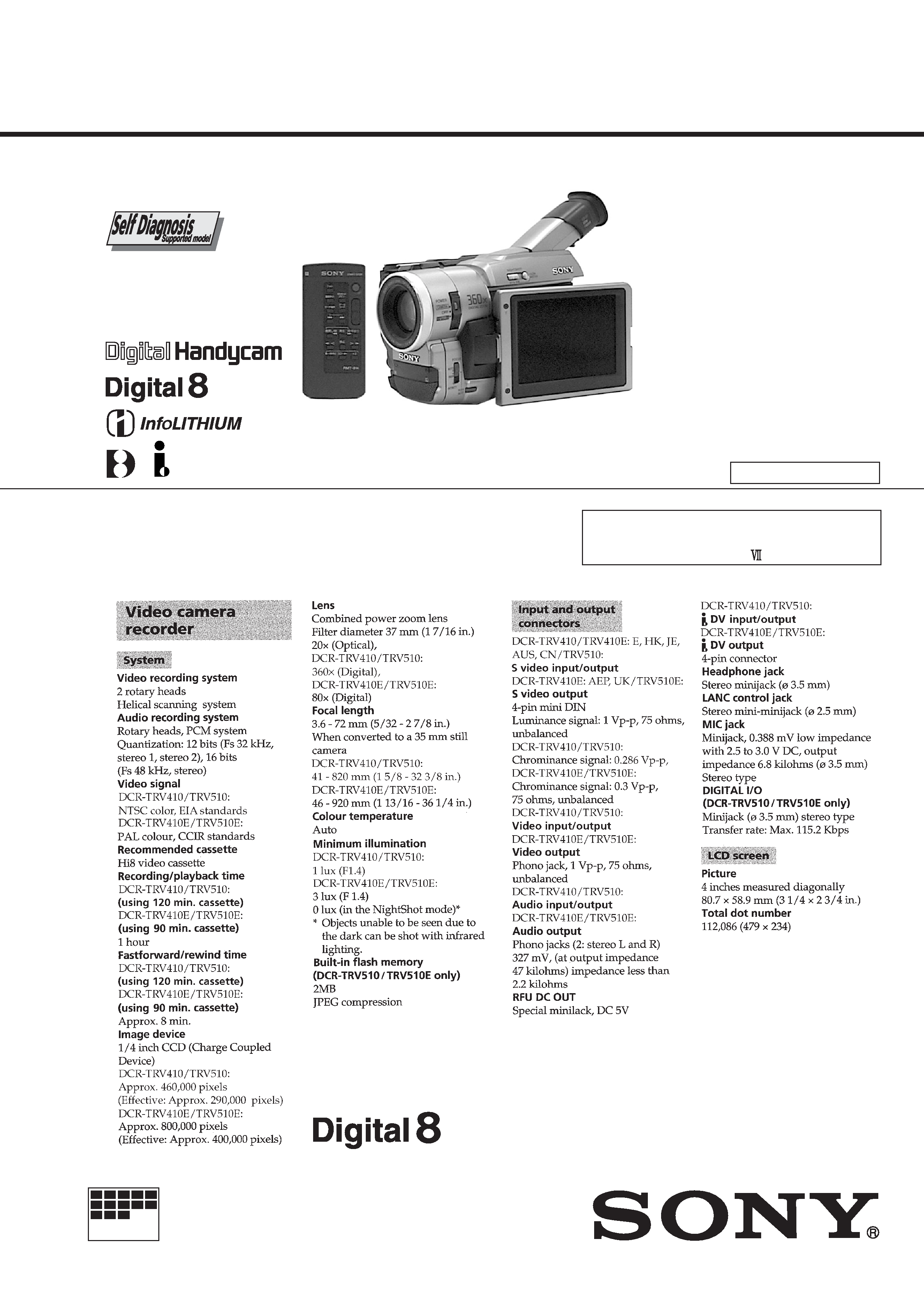
DIGITAL VIDEO CAMERA RECORDER
Photo: DCR-TRV510
For MECHANISM ADJUSTMENT, refer to
the "8mm Video MECHANICAL
ADJUSTMENT MANUAL
" (9-973-801-11).
SPECIFICATIONS
· Abbreviation
HK : Hong Kong model
JE
: Tourist model
AUS : Australian model
CN : Chinese model
NTSC MODEL : DCR-TRV410/TRV510
PAL MODEL
: DCR-TRV410E/TRV510E
SERVICE MANUAL
Ver 1.2
2001. 01
-- 2 --
SAFETY-RELATED COMPONENT WARNING!!
COMPONENTS IDENTIFIED BY MARK
! OR DOTTED LINE WITH
MARK
! ON THE SCHEMATIC DIAGRAMS AND IN THE PARTS
LIST ARE CRITICAL TO SAFE OPERATION. REPLACE THESE
COMPONENTS WITH SONY PARTS WHOSE PART NUMBERS
APPEAR AS SHOWN IN THIS MANUAL OR IN SUPPLEMENTS
PUBLISHED BY SONY.
ATTENTION AU COMPOSANT AYANT RAPPORT
À LA SÉCURITÉ!
LES COMPOSANTS IDENTIFÉS PAR UNE MARQUE
! SUR LES
DIAGRAMMES SCHÉMATIQUES ET LA LISTE DES PIÈCES SONT
CRITIQUES POUR LA SÉCURITÉ DE FONCTIONNEMENT. NE
REMPLACER CES COMPOSANTS QUE PAR DES PIÈSES SONY
DONT LES NUMÉROS SONT DONNÉS DANS CE MANUEL OU
DANS LES SUPPÉMENTS PUBLIÉS PAR SONY.
1.
Check the area of your repair for unsoldered or poorly-soldered
connections. Check the entire board surface for solder splashes
and bridges.
2.
Check the interboard wiring to ensure that no wires are
"pinched" or contact high-wattage resistors.
3.
Look for unauthorized replacement parts, particularly
transistors, that were installed during a previous repair. Point
them out to the customer and recommend their replacement.
4.
Look for parts which, through functioning, show obvious signs
of deterioration. Point them out to the customer and
recommend their replacement.
5.
Check the B+ voltage to see it is at the values specified.
6.
Flexible Circuit Board Repairing
· Keep the temperature of the soldering iron around 270°C
during repairing.
· Do not touch the soldering iron on the same conductor of the
circuit board (within 3 times).
· Be careful not to apply force on the conductor when soldering
or unsoldering.
SAFETY CHECK-OUT
After correcting the original service problem, perform the following
safety checks before releasing the set to the customer.
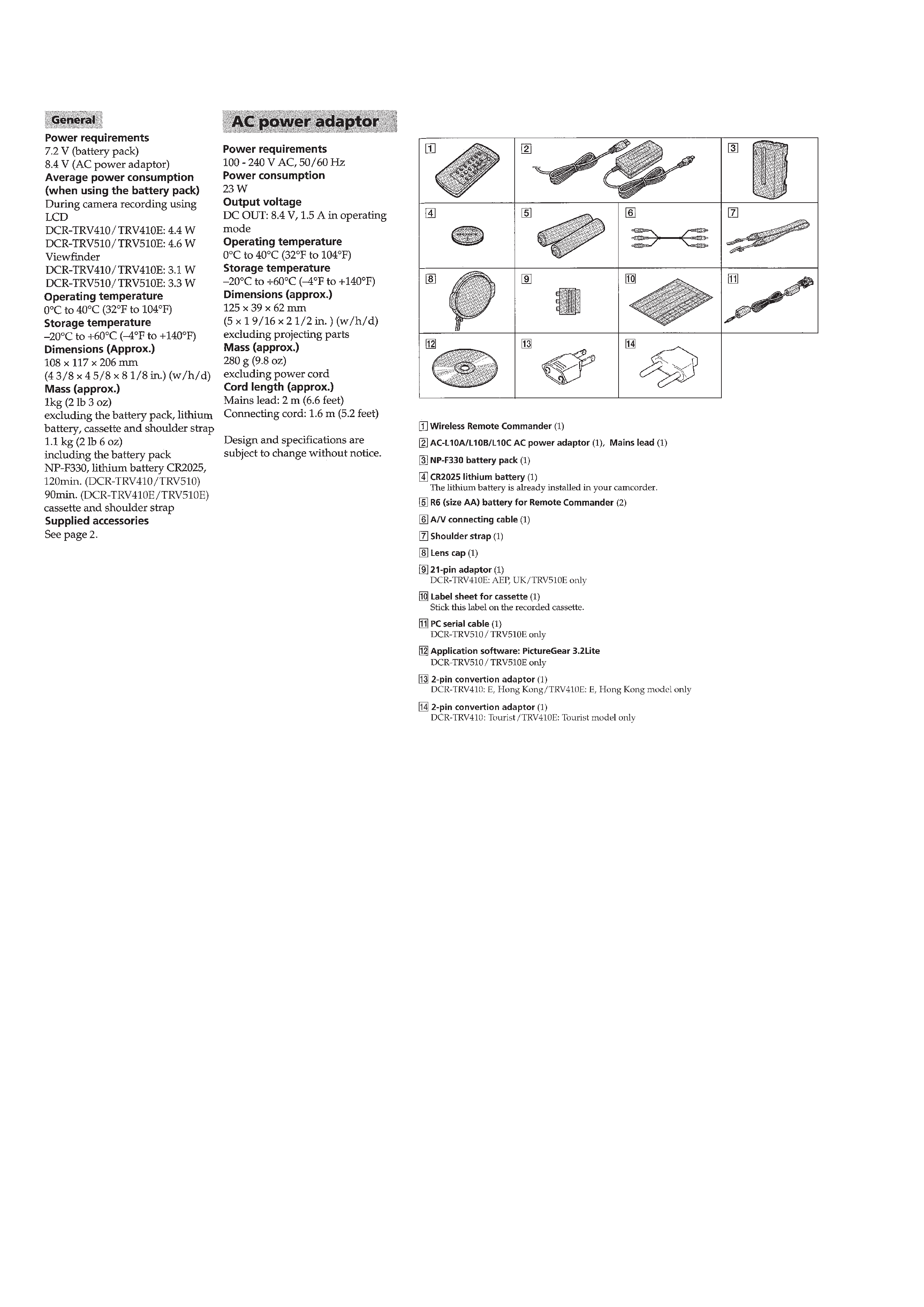
Supplied accessories

-- 3 --
Model
Destination
Color system
Lens
Digital zoom
CCD imager
LINE REC
RS232C
CD board
DCR-
TRV410
E, HK, JE
NTSC
20
×
360
×
720H
®
!
CD-212
DCR-
TRV410E
AEP, UK
PAL
20
×
80
×
960H
!
!
CD-213
E, HK,AUS,
CN, JE
PAL
20
×
360
×
960H
®
!
CD-213
DCR-
TRV510
US, CND
NTSC
20
×
360
×
720H
®
®
CD-212
DCR-
TRV510E
AEP, UK
PAL
20
×
80
×
960H
!
®
CD-213
Table for differences of function
Remark
NTSC : X251 is 28.6363MHz
PAL : X251 is 28.375MHz
960H: with IC503 of VC-213 board, CD-213 board
720H: CD-212 board
®: with REC button and Q641- 644 of VC-213 board
®: PC-72 board
·
Abbreviation
CND
: Canadian model
HK
: Hong Kong model
AUS
: Australian model
CN
: Chinese model
JE
: Tourist model

-- 4 --
TABLE OF CONTENTS
SERVICE NOTE
1.
POWER SUPPLY DURING REPAIRS ····························· 7
2.
TO TAKE OUT A CASSETTE WHEN NOT EJECT
(FORCE EJECT) ································································ 7
SELF-DIAGNOSIS FUNCTION
1.
Self-diagnosis Function ······················································ 8
2.
Self-diagnosis Display ························································ 8
3.
Service Mode Display ························································ 8
3-1.
Display Method ·································································· 8
3-2.
Switching of Backup No. ··················································· 8
3-3.
End of Display ···································································· 8
4.
Self-dignosis Code Table ···················································· 9
1.
GENERAL
Checking supplied accessories ·················································· 1-1
Quick Start Guide ······································································ 1-1
Getting Started ··········································································· 1-2
Using this manual ·································································· 1-2
Step 1 Preparing the power supply ······································· 1-2
Installing the battery pack ·················································· 1-2
Charging the battery pack ·················································· 1-2
Connecting to the mains ···················································· 1-4
Step 2 Inserting a cassette ···················································· 1-4
Recording Basics ···································································· 1-5
Recording a picture ································································ 1-5
Shooting backlit subjects (BACK LIGHT) ························ 1-7
Shooting in the dark (NightShot) ······································· 1-7
Checking the recording
END SEARCH/EDITSEARCH/Rec Review ····················· 1-7
Playback Basics ······································································ 1-8
Playing back a tape ································································ 1-8
Viewing the recording on TV ················································ 1-9
Advanced Recording Operations ············································· 1-10
Photo recording ···································································· 1-10
Using the wide mode ··························································· 1-11
Using the fader function ······················································ 1-11
Using special effects Picture effect ··································· 1-12
Using special effects Digital effect ··································· 1-12
Using the PROGRAM AE function ····································· 1-13
Adjusting the exposure manually ········································ 1-14
Focusing manually ······························································· 1-14
Inserting a scene ·································································· 1-15
Advanced Playback Operations ··············································· 1-15
Playing back a tape with picture effects ······························ 1-15
Playing back a tape with digital effects ······························· 1-15
Quickly locating a scene using the zero set
memory function ·································································· 1-16
Searching a recording by date ·············································· 1-16
Searching for a photo Photo search/Photo scan ················ 1-17
Editing on Other Equipment ···················································· 1-17
Dubbing a tape ····································································· 1-17
Flash Memory Operations (DCR-TRV510/TRV510E only)
Using the flash memory function introduction ················· 1-18
Recording still images in the built-in flash memory
Memory photo recording ·················································· 1-19
Recording an image from a recorded tape as a still image ·· 1-20
Copying still images from a recorded tape PHOTO SAVE · 1-21
Viewing a still picture Memory photo playback ··············· 1-21
Playing back images in a continuous loop SLIDE SHOW · 1-23
Preventing accidental erasure PROTECT ························· 1-23
Deleting images DELETE ················································ 1-23
Customizing Your Camcorder ················································· 1-24
Changing the MENU settings ·············································· 1-24
Resetting the date and time ·················································· 1-26
Additional Information ···························································· 1-26
Digital8
system, recording and playback ························ 1-26
Changing the lithium battery in your camcorder ················· 1-27
Troubleshooting ··································································· 1-27
Self-diagnosis display ·························································· 1-28
Warning indicators and messages ········································ 1-29
Using your camcorder abroad ·············································· 1-29
Maintenance information and precautions ··························· 1-29
Quick Reference ······································································ 1-30
Identifying the parts and controls ········································ 1-30
Quick Function Guide ························································· 1-33
2.
DISASSEMBLY
2-1.
LCD Unit, PD-106 Board ················································ 2-2
2-2.
Front Panel Assembly, Cabinet (R) Assembly ················ 2-3
2-3.
PC-72 Board (TRV510/TRV510E) ································· 2-3
2-4.
MA-356 Board ································································ 2-3
2-5.
Mechanism Deck ····························································· 2-4
2-6.
EVF Block Assembly ······················································ 2-5
2-7.
CF-64 Board ···································································· 2-5
2-8.
VF-126 Board ·································································· 2-6
2-9.
Lens Block ······································································· 2-7
2-10. Mechanism Deck, VC-213, DD-117, PJ-97 Boards ········ 2-8
2-11. Circuit Boards Location ················································ 2-10
2-12. Flexible Boards Location ·············································· 2-11
3.
BLOCK DIAGRAMS
3-1.
Overall Block Diagram (1) ·············································· 3-1
3-2.
Overall Block Diagram (2) ·············································· 3-4
3-3.
Power Block Diagram (1) ················································ 3-7
3-4.
Power Block Diagram (2) ·············································· 3-10
4.
PRINTED WIRING BOARDS AND
SCHEMATIC DIAGRAMS
4-1.
Frame Schematic Diagram-1 ··········································· 4-1
Frame Schematic Diagram-2 ··········································· 4-5
4-2.
Printed Wiring Boards and Schematic Diagrams ············ 4-9
· CD-212 (CCD Imager)
Printed Wiring Board and
Schematic Diagram ······································· 4-10
· CD-213 (CCD Imager)
Printed Wiring Board and
Schematic Diagram ······································· 4-13
· VC-213 (Camera Processor)(1/13)
Schematic Diagram ....................................... 4-15
· VC-213 (Y/C Processor)(2/13)
Schematic Diagram ······································· 4-18
· VC-213 (Lens Motor Drive)(3/13)
Schematic Diagram ······································· 4-21
· VC-213 (I/O SEL, IR, BBI)(4/13)
Schematic Diagram ······································· 4-25
· VC-213 (VFD)(5/13)
Schematic Diagram ······································· 4-29
· VC-213 (SFD, TFD, LIP)(6/13)
Schematic Diagram ······································· 4-33
· VC-213 (TRX, TRF, TRW)(7/13)
Schematic Diagram ······································· 4-35
· VC-213 (8mm PB RF AMP, D/A Converter)(8/13)
Schematic Diagram ······································· 4-40
· VC-213 (8mm AFM Processor)(9/13)
Schematic Diagram ······································· 4-43
· VC-213 (8mm Mechanism Control)(10/13)
Schematic Diagram ······································· 4-49
· VC-213 (DV Mechanism Control)(11/13)
Schematic Diagram ······································· 4-51
· FP-249 (S/T Reel Sensor), FP-356 (Top Sensor),
FP-355 (Tape LED) Flexible Board ···························· 4-55
· VC-213 (Servo)(12/13)
Schematic Diagram ······································· 4-56

-- 5 --
· VC-213 (HI Control)(13/13)
Schematic Diagram ······································· 4-59
· VC-213 (Camera Processor, Y/C Processor, Lens Motor
Drive, IN/OUT Select, IR Transmitter, Base Band Input,
VFD, SFD, TFD, LIP, TRX, TRF, TRW, 8mm PB RF
AMP, D/A Converter, 8mm AFM Processor, 8mm
Mechanism Control, DV Mechanism Control, Servo,
HI Control)
Printed Wiring Board ···································· 4-65
· SE-88 (Steady Shot), PJ-97 (AV IN/OUT)
Printed Wiring Boards ··································· 4-70
· SE-88 (Steady Shot), PJ-97 (AV IN/OUT)
Schematic Diagrams ····································· 4-73
· MA-356 (Stereo MIC AMP)
Printed Wiring Board ···································· 4-75
· MA-356 (Stereo MIC AMP)
Schematic Diagram ······································· 4-77
· CF-64 (User Control)
Printed Wiring Board .................................... 4-80
· CF-64 (User Control)
Schematic Diagram ······································· 4-83
· PC-72 (JPEG, Honey, Shutter, D/D Conv., Interface,
Flash Memory)
Printed Wiring Board .................................... 4-86
· PC-72 (Honey, JPEG)(1/3)
Schematic Diagram ······································· 4-89
· PC-72 (Digital Still Cont, Flash Memory)(2/3)
Schematic Diagram ······································· 4-93
· PC-72 (D/D Conv., Interface)(3/3)
Schematic Diagram ······································· 4-97
· PD-106 (RGB Decoder, LCD, Timing Generator,
Back Light Drive)
Printed Wiring Board ·································· 4-100
· PD-106 (RGB Decoder, LCD)(1/2)
Schematic Diagram ····································· 4-103
· PD-106 (Timing Generator, Back Light Drive)(2/2)
Schematic Diagram ····································· 4-106
· FK-8500, SS-8500 (Control Switch Block)
Schematic Diagram ····································· 4-109
· VF-126 (Color EVF)
Printed Wiring Board .................................. 4-111
· VF-126 (Color EVF)
Schematic Diagram ····································· 4-113
· DD-117 (DC/DC Converter)
Printed Wiring Board ·································· 4-118
· DD-117 (DC/DC Converter)
Schematic Diagram ····································· 4-121
5.
ADJUSTMENTS
1.
Before starting adjustment ··············································· 5-1
1-1.
Adjusting items when replacing main parts and boards ·· 5-2
5-1.
CAMERA SECTION ADJUSTMENT ··························· 5-4
1-1.
Preparations before Adjustment (Camera Section) ········· 5-4
1-1-1. List of Service Tools ························································ 5-4
1-1-2. Preparations ····································································· 5-5
1-1-3. Precaution ········································································ 5-7
1.
Setting the Switch ···························································· 5-7
2.
Order of Adjustments ······················································ 5-7
3.
Subjects ··········································································· 5-7
1-2.
Initialization of C, D, E, F Page Data ······························ 5-8
1-2-1. Initialization of C Page Data ··········································· 5-8
1.
Initializing the C Page Data ············································· 5-8
2.
Modification of C Page Data ··········································· 5-8
3.
C Page Table ···································································· 5-8
1-2-2. Initialization of D Page Data ········································· 5-10
1.
Initializing the D Page Data ·········································· 5-10
2.
Modification of D Page Data ········································· 5-10
3.
D Page Table ·································································· 5-10
1-2-3. Initialization of B Page Data
(DCR-TRV510/TRV510E) ············································ 5-12
1.
Initializing the B Page Data ··········································· 5-12
2.
Modification of B Page Data ········································· 5-12
3.
B Page Table ·································································· 5-12
1-2-4. Initialization of E, F Page Data ····································· 5-14
1.
Initializing the E, F Page Data ······································· 5-14
2.
Modification of E, F Page Data ····································· 5-14
3.
F Page Table ·································································· 5-15
4.
E Page Table ·································································· 5-17
1-3.
Camera System Adjustments ········································· 5-20
1.
HALL Adjustment ························································· 5-20
2.
Flange Back Adjustment (Using Minipattern Box) ······· 5-21
3.
Flange Back Adjustment (Using Flange Back Adjustment
Chart and Subject More Than 500m Away) ·················· 5-22
3-1.
Flange Back Adjustment (1) ·········································· 5-22
3-2.
Flange Back Adjustment (2) ·········································· 5-22
4.
Flange Back Check ························································ 5-23
5.
Picture Frame Setting ···················································· 5-23
6.
AGC Gain Calibration Adjustment ······························· 5-24
7.
Color Reproduction Adjustment ···································· 5-25
8.
IRIS IN/OUT Adjustment ············································· 5-26
9.
Auto White Balance Standard Data Input ····················· 5-27
10.
Auto White Balance Adjustment ··································· 5-27
11.
White Balance Check ···················································· 5-28
12.
Angular Velocity Sensor Sensitivity Data Check ·········· 5-29
1-4.
Color Electronic Viewfinder System Adjustments ········ 5-30
1.
EVF Initial Data Input ··················································· 5-30
2.
VCO Adjustment (VF-126 board) ································· 5-31
3.
Bright Adjustment (VF-126 board) ······························· 5-31
4.
Contrast Adjustment (VF-126 board) ···························· 5-32
5.
Backlight Consumption Current Adjustment
(VF-126 board) ······························································ 5-32
6.
White Balance Adjustment (VF-126 board) ·················· 5-33
1-5.
LCD System Adjustments ············································· 5-34
1.
LCD Initial Data Input (1) ············································· 5-34
2.
LCD Initial Data Input (2) ············································· 5-34
3.
VCO Adjustment (PD-106 board) ································· 5-35
4.
D range Adjustment (PD-106 board) ····························· 5-35
5.
Bright Adjustment (PD-106 board) ······························· 5-36
6.
Contrast Adjustment (PD-106 board) ···························· 5-36
7.
V-COM Level Adjustment (PD-106 board) ·················· 5-37
8.
Color Adjustment (PD-106 board) ································ 5-37
9.
V-COM Adjustment (PD-106 board) ···························· 5-38
10.
White Balance Adjustment (PD-106 board) ·················· 5-38
5-2.
MECHANISM SECTION ADJUSTMENT ·················· 5-39
2-1.
Hi8/Standard 8mm Mode ·············································· 5-39
2-1-1. Operating Without Cassette ··········································· 5-39
2-1-2. Tape Path Adjustment ···················································· 5-39
1.
Preparations for Adjustment ·········································· 5-39
2-2.
Digital8 Mode ································································ 5-40
2-2-1. How to Enter Record Mode Without Cassette ·············· 5-40
2-2-2. How to Enter Playback Mode Without Cassette ··········· 5-40
2-2-3. Overall Tape Path Check ··············································· 5-40
1.
Recording of the tape path check signal ························ 5-40
2.
Tape path check ····························································· 5-40
5-3.
VIDEO SECTION ADJUSTMENT ······························ 5-41
3-1.
Preparations Before Adjustments ·································· 5-41
3-1-1. Equipment to Required ·················································· 5-41
3-1-2. Precautions on Adjusting ··············································· 5-42
3-1-3. Adjusting Connectors ···················································· 5-43
3-1-4. Connecting the Equipment ············································ 5-43
3-1-5. Alignment Tape ····························································· 5-44
3-1-6. Input/Output Level and Impedance ······························· 5-45
3-2.
System Control System Adjustment ······························ 5-46
1.
Initialization of B, C, D, E, F Page Data ······················· 5-46