SERVICE MANUAL
M2000 MECHANISM
DIGITAL VIDEO CAMERA RECORDER
SPECIFICATIONS
Photo : DCR-TRV340
-- Continued on next page --
DCR-TRV240/TRV340
RMT-814
US Model
Canadian Model
E Model
Hong Kong Model
DCR-TRV240/TRV340
Korea Model
Tourist Model
Argentina Model
Brazilian Model
DCR-TRV340
Level 2
Ver 1.4 2005. 06
For MECHANISM ADJUSTMENT, refer to the
"8mm Video MECHANICAL ADJUSTMENT
MANUAL
IX
M2000 MECHANISM " (9-929-
861-11).
On the VC-276 board
This service manual provides the information that is premised the
circuit board replacement service and not intended repair inside the
VC-276 board.
Therefore, schematic diagram, printed wiring board, waveforms,
mounted parts location and electrical parts list of the VC-276 board
are not shown.
The following pages are not shown.
Schematic diagram ..................................... Pages 4-29 to 4-78
Printed wiring board .................................... Pages 4-79 to 4-82
Waveforms and mounted parts location ..... Pages 4-85 to 4-89
Electrical parts list ....................................... Pages 6-14 to 6-25

-- 2 --
SAFETY-RELATED COMPONENT WARNING!!
COMPONENTS IDENTIFIED BY MARK 0 OR DOTTED LINE WITH
MARK 0 ON THE SCHEMATIC DIAGRAMS AND IN THE PARTS
LIST ARE CRITICAL TO SAFE OPERATION. REPLACE THESE
COMPONENTS WITH SONY PARTS WHOSE PART NUMBERS
APPEAR AS SHOWN IN THIS MANUAL OR IN SUPPLEMENTS
PUBLISHED BY SONY.
DCR-TRV240/TRV340
1.
Check the area of your repair for unsoldered or poorly-soldered
connections. Check the entire board surface for solder splashes
and bridges.
2.
Check the interboard wiring to ensure that no wires are
"pinched" or contact high-wattage resistors.
3.
Look for unauthorized replacement parts, particularly
transistors, that were installed during a previous repair. Point
them out to the customer and recommend their replacement.
4.
Look for parts which, through functioning, show obvious signs
of deterioration. Point them out to the customer and
recommend their replacement.
5.
Check the B+ voltage to see it is at the values specified.
6.
Flexible Circuit Board Repairing
· Keep the temperature of the soldering iron around 270°C
during repairing.
· Do not touch the soldering iron on the same conductor of the
circuit board (within 3 times).
· Be careful not to apply force on the conductor when soldering
or unsoldering.
Unleaded solder
Boards requiring use of unleaded solder are printed with the lead-
free mark (LF) indicating the solder contains no lead.
(Caution: Some printed circuit boards may not come printed with
the lead free mark due to their particular size.)
: LEAD FREE MARK
Unleaded solder has the following characteristics.
· Unleaded solder melts at a temperature about 40°C higher than
ordinary solder.
Ordinary soldering irons can be used but the iron tip has to be
applied to the solder joint for a slightly longer time.
Soldering irons using a temperature regulator should be set to
about 350°C.
Caution: The printed pattern (copper foil) may peel away if the
heated tip is applied for too long, so be careful!
· Strong viscosity
Unleaded solder is more viscous (sticky, less prone to flow) than
ordinary solder so use caution not to let solder bridges occur such
as on IC pins, etc.
· Usable with ordinary solder
It is best to use only unleaded solder but unleaded solder may
also be added to ordinary solder.
SAFETY CHECK-OUT
After correcting the original service problem, perform the following
safety checks before releasing the set to the customer.
ATTENTION AU COMPOSANT AYANT RAPPORT
À LA SÉCURITÉ!
LES COMPOSANTS IDENTIFÉS PAR UNE MARQUE 0 SUR LES
DIAGRAMMES SCHÉMATIQUES ET LA LISTE DES PIÈCES SONT
CRITIQUES POUR LA SÉCURITÉ DE FONCTIONNEMENT. NE
REMPLACER CES COMPOSANTS QUE PAR DES PIÈSES SONY
DONT LES NUMÉROS SONT DONNÉS DANS CE MANUEL OU
DANS LES SUPPÉMENTS PUBLIÉS PAR SONY.
CAUTION :
Danger of explosion if battery is incorrectly replaced.
Replace only with the same or equivalent type.
AC power adaptor
Power requirements
100 240 V AC, 50/60 Hz
Power consumption
23 W
Output voltage
DC OUT: 8.4 V, 1.5 A in the
operating mode
Operating temperature
0
°C to 40°C (32°F to 104°F)
Storage temperature
20
°C to + 60°C (4°F to + 140°F)
Dimensions (approx.)
125
× 39 × 62 mm
(5
× 1 9/16 × 2 1/2 in. ) (w/h/d)
excluding projecting parts
Mass (approx.)
280 g (9.8 oz)
excluding power cord
Battery pack
Maximum output voltage
DC 8.4 V
Mean output voltage
DC 7.2 V
Capacity
5.0 Wh (700 mAh)
Operating temperature
0
°C to 40°C (32°F to 104°F)
Dimensions (approx.)
38.2
× 20.5 × 55.6 mm
(1 9/16
× 13/16 × 2 1/4 in.)
(w/h/d)
Mass (approx.)
65 g (2.3 oz)
Type
Lithium ion
"Memory Stick"
(DCR-TRV340 only)
Memory
Flash memory
8MB: MSA-8A
Operating voltage
2.7 3.6 V
Power consumption
Approx. 45 mA in the operating
mode
Approx. 130
µA in the standby
mode
Dimensions (approx.)
50
× 2.8 × 21.5 mm
(2
× 1/8 × 7/8 in.) (w/h/d)
Mass (approx.)
4 g (0.14 oz)
Design and specifications are
subject to change without notice.
General
Power requirements
7.2 V (battery pack)
8.4 V (AC power adaptor)
Average power consumption
(when using the battery pack)
During camera recording using
LCD
3.8 W
Viewfinder
3.0 W
Operating temperature
0
°C to 40°C (32°F to 104°F)
Recommended charging
temperature
10
°C to 30°C (50°F to 86°F)
Storage temperature
20
°C to + 60°C (4°F to + 140°F)
Dimensions (approx.)
206
× 101 × 85 mm
(8 1/8
× 4 × 3 3/8 in.)
(w/h/d)
Mass (approx.)
DCR-TRV240:
890 g (1 lb 15 oz)
DCR-TRV340:
900 g (1 lb 15 oz)
excluding the battery pack,
cassette, lens cap and shoulder
strap
DCR-TRV240:
1 030 g (2 lb 4 oz)
DCR-TRV340:
1 040 g (2 lb 4 oz)
including the battery pack
NP-FM30, 120min. Hi8 cassette,
lens cap and shoulder strap
Supplied accessories
See page 3.
-- 3 --
DCR-TRV240/TRV340
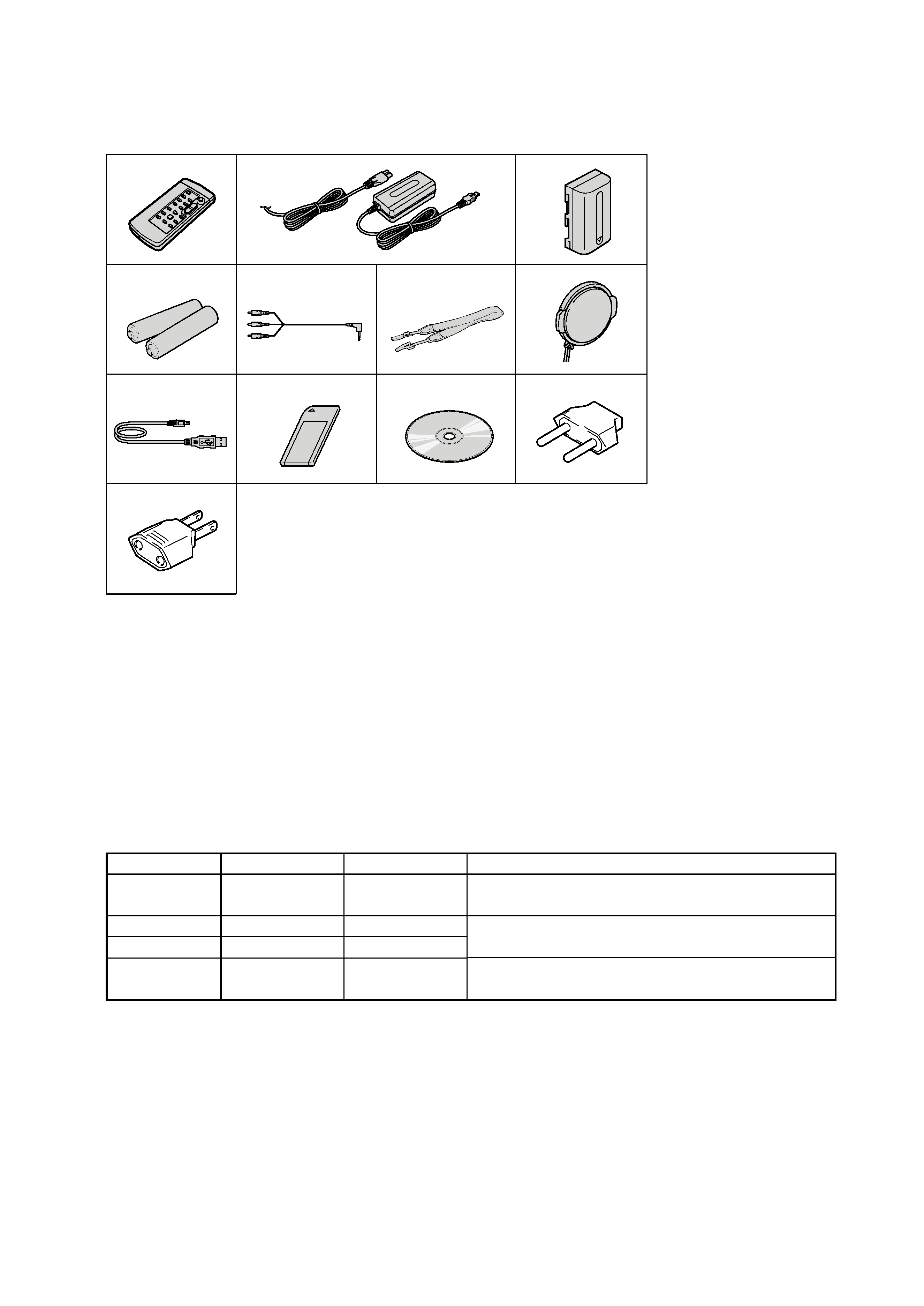
· SUPPLIED ACCESSORIES
Make sure that the following accessories are supplied with your camcorder.
· Abbreviation
CND : Canadian model
HK
: Hong Kong model
KR
: Korea model
JE
: Tourist model
AR
: Argentina model
BR
: Brazilian model
Table for difference of function
Model
Destination
Memory Stick
MPEG Movie
Intelligent
Accessory Shoe
DCR-TRV240
US, CND, E, HK
8p
DCR-TRV340
US, CND, E, HK,
KR, JE, AR, BR
a
f
15p
Remark
a : with VC-276 board IC4901, 4903, 4905, 5001, 5101, 5102
: with VC-276 board IC4801, 4802
15p : Printer ready
1
Wireless Remote Commander (1)
2
AC-L10A/L10B/L10C AC power
adaptor (1), Power cord (1)
3
NP-FM30 battery pack (1)
4
Size AA (R6) battery for Remote
Commander (2)
5
A/V connecting cable (1)
6
Shoulder strap (1)
7
Lens cap (1)
8
USB cable (1)
9
"Memory Stick" (1) (DCR-TRV340 only)
0
CD-ROM (SPVD-008 USB Driver) (1)
12
3
45
6
7
89
0
qa
2-pin conversion adaptor (1)
DCR-TRV340 : Tourist model
qs
2-pin conversion adaptor (1)
DCR-TRV240 : E, Hong Kong/
TRV340 : E, Hong Kong model
qs
qa

-- 4 --
DCR-TRV240/TRV340
TABLE OF CONTENTS
SERVICE NOTE
1.
POWER SUPPLY DURING REPAIRS ····························· 7
2.
TO TAKE OUT A CASSETTE WHEN NOT EJECT
(FORCE EJECT) ································································ 7
SELF-DIAGNOSIS FUNCTION
1.
Self-diagnosis Function ······················································ 8
2.
Self-diagnosis Display ························································ 8
3.
Service Mode Display ························································ 8
3-1.
Display Method ·································································· 8
3-2.
Switching of Backup No. ··················································· 8
3-3.
End of Display ···································································· 8
4.
Self-diagnosis Code Table ·················································· 9
1.
GENERAL
Main features ············································································· 1-1
Checking supplied accessories ·················································· 1-1
Quick Start Guide ······································································ 1-1
Getting Started
Using this manual ·································································· 1-2
Step 1 Preparing the power supply ········································ 1-2
Installing the battery pack ··················································· 1-2
Charging the battery pack ·················································· 1-2
Connecting to a wall outlet ················································· 1-3
Step 2 Setting the date and time ············································ 1-3
Step 3 Inserting a cassette ······················································ 1-4
Recording Basics
Recording a picture ································································ 1-4
Shooting backlit subjects BACK LIGHT ··························· 1-6
Shooting in the dark NightShot/Super NightShot/
Color Slow Shutter ····························································· 1-6
Self-timer recording (DCR-TRV340 only) ···························· 1-7
Checking recordings END SEARCH/EDITSEARCH/
Rec Review ········································································· 1-7
Playback Basics
Playing back a tape ································································ 1-7
To display the screen indicators Display function ··········· 1-8
Viewing recordings on TV ····················································· 1-8
Advanced Recording Operations
Recording still images on a tape Tape Photo recording ······ 1-9
Using the wide mode ····························································· 1-9
Using the fader function ····················································· 1-10
Using special effects Picture effect ··································· 1-11
Using special effects Digital effect ··································· 1-11
Using the PROGRAM AE function ····································· 1-12
Adjusting the exposure manually ········································ 1-12
Focusing manually ······························································· 1-12
Interval recording ································································· 1-13
Frame by frame recording Frame recording ····················· 1-13
Superimposing a title ··························································· 1-13
Making your own titles ························································ 1-14
Inserting a scene ·································································· 1-14
Advanced Playback Operations
Playing back tapes with picture effects ································ 1-15
Playing back tapes with digital effects ································ 1-15
Enlarging recorded images Tape PB ZOOM ···················· 1-15
Quickly locating a scene ZERO SET MEMORY ············· 1-16
Searching a recording by date DATE SEARCH ··············· 1-16
Searching for a photo
PHOTO SEARCH/PHOTO SCAN ································ 1-16
Editing
Dubbing a tape ····································································· 1-17
Dubbing only desired scenes Digital program editing
(on tapes) ·········································································· 1-17
Capturing images from an analog video unit on your
computer Signal convert function ·································· 1-21
Recording video or TV programs ········································ 1-21
Inserting a scene from a VCR Insert Editing ···················· 1-22
Viewing images recorded on a tape on your computer
(Windows users only) ······················································· 1-22
Customizing Your Camcorder
Changing the menu settings ················································· 1-25
"Memory Stick" operations (DCR-TRV340 only)
Using "Memory Stick" Introduction ································ 1-28
Recording still images on "Memory Stick"s
Memory Photo recording ··············································· 1-30
Superimposing a still image in the "Memory Stick"
on an image MEMORY MIX ········································ 1-31
Recording images from a tape as still images ····················· 1-32
Copying still images from a tape PHOTO SAVE ············· 1-33
Recording moving pictures on "Memory Stick"s
MPEG movie recording ················································· 1-34
Recording pictures from a tape as moving pictures ············· 1-34
Recording edited pictures as a moving picture
Digital program editing (on "Memory Stick"s) ············· 1-35
Viewing still images Memory Photo playback ················· 1-36
Viewing moving pictures MPEG movie playback ············ 1-37
Viewing images recorded on "Memory Stick"s
on your computer ······························································ 1-37
Copying images recorded on "Memory Stick"s to tape ······ 1-40
Enlarging still images recorded on "Memory Stick"s
Memory PB ZOOM ······················································· 1-40
Playing back images in a continuous loop SLIDE SHOW ··· 1-41
Preventing accidental erasure Image protection ··············· 1-41
Deleting images DELETE ················································ 1-41
Writing a print mark PRINT MARK ································ 1-42
Using the optional printer ···················································· 1-43
Troubleshooting
Types of trouble and how to correct trouble ························ 1-43
Self-diagnosis display ·························································· 1-45
Warning indicators and messages ········································ 1-45
Additional Information
Digital8
system, recording and playback ························ 1-45
About the "InfoLITHIUM" battery pack ····························· 1-46
About i.LINK ······································································· 1-46
Using your camcorder abroad ·············································· 1-47
Maintenance information and precautions ··························· 1-47
Quick Reference
Identifying parts and controls ·············································· 1-48
2.
DISASSEMBLY
2-1.
LCD UNIT, PD-160 BOARD ········································· 2-2
2-2.
FRONT PANEL SECTION, SI-032 BOARD ················· 2-3
2-3.
CABINET (R) SECTION ··············································· 2-4
2-4.
LENS SECTION, CD-357 BOARD ······························· 2-5
2-5.
EVF SECTION, LB-076 BOARD ·································· 2-6
2-6.
BATTERY PANEL SECTION,
BATTERY TERMINAL BOARD ··································· 2-7
2-7.
MEMORY STICK 10P CONNECTOR
(MEMORY STICK MODEL) (TRV340) ······················· 2-7
2-8.
CONTROL SWITCH BLOCK (SS-1380) ······················ 2-8
2-9.
CABINET (L) SECTION,
CS FRAME ASSEMBLY (25) ········································ 2-8
2-10. VC-276 BOARD ····························································· 2-9
2-11. MECHANISM DECK ····················································· 2-9
2-12. CONTROL SWITCH BLOCK (CF-2500) ··················· 2-12
2-13. CONTROL SWITCH BLOCK (FK-2500) ··················· 2-12
2-14. HINGE SECTION ························································· 2-13
2-15. CIRCUIT BOARDS LOCATION ································· 2-14
2-16. FLEXIBLE BOARDS LOCATION ······························ 2-15

-- 5 --
DCR-TRV240/TRV340
3.
BLOCK DIAGRAMS
3-1.
OVERALL BLOCK DIAGRAM (1/5) ··························· 3-1
3-2.
OVERALL BLOCK DIAGRAM (2/5) ··························· 3-3
3-3.
OVERALL BLOCK DIAGRAM (3/5) ··························· 3-5
3-4.
OVERALL BLOCK DIAGRAM (4/5) ··························· 3-7
3-5.
OVERALL BLOCK DIAGRAM (5/5)(DCR-TRV240) ···· 3-9
3-5.
OVERALL BLOCK DIAGRAM (5/5)(DCR-TRV340) ··· 3-11
3-6.
POWER BLOCK DIAGRAM (1/3) ······························ 3-13
3-7.
POWER BLOCK DIAGRAM (2/3) ······························ 3-15
3-8.
POWER BLOCK DIAGRAM (3/3) ······························ 3-17
4.
PRINTED WIRING BOARDS AND
SCHEMATIC DIAGRAMS
4-1.
FRAME SCHEMATIC DIAGRAM (1/2) ······················· 4-1
FRAME SCHEMATIC DIAGRAM (2/2) ······················· 4-3
4-2.
PRINTED WIRING BOARDS AND
SCHEMATIC DIAGRAMS ············································ 4-5
· CD-357 (CCD IMAGER)
PRINTED WIRING BOARD AND
SCHEMATIC DIAGRAM ······························ 4-7
· LB-076 (EVF, BACK LIGHT)
PRINTED WIRING BOARD AND
SCHEMATIC DIAGRAM ······························ 4-9
· SI-032 (STEADY SHOT, LASER LINK)
PRINTED WIRING BOARD ······················· 4-11
· FP-411 FLEXIBLE BOARD ····································· 4-12
· SI-032 (STEADY SHOT, LASER LINK)
SCHEMATIC DIAGRAM ···························· 4-13
· PD-160 (CHA, DISPLAY DRIVE, BACK LIGHT, LCD
DRIVE, TG)
PRINTED WIRING BOARD ······················· 4-15
· FP-412 FLEXIBLE BOARD ····································· 4-18
· PD-160 (CHA, DISPLAY DRIVE, BACK LIGHT)(1/2)
SCHEMATIC DIAGRAM ···························· 4-19
· PD-160 (LCD DRIVE, TG)(2/2)
SCHEMATIC DIAGRAM ···························· 4-21
· CONTROL SWITCH BLOCK (CF-2500, FK-2500)
SCHEMATIC DIAGRAM ···························· 4-23
· LS-057 (S/T REEL SENSOR), FP-228 (DEW SENSOR),
FP-299 (MODE SWITCH), FP-300 (TAPE TOP),
FP-302 (TAPE END), FP-301 (TAPE LED)
FLEXIBLE BOARDS AND
SCHEMATIC DIAGRAMS ·························· 4-25
· CONTROL SWITCH BLOCK (SS-1380)
SCHEMATIC DIAGRAM ···························· 4-27
· FP-410 FLEXIBLE BOARD ····································· 4-28
Shematic diagram and printed wiring board of the
VC-276 board are not shown.
Pages from 4-29 to 4-82 are not shown.
4-3.
WAVEFORMS ······························································ 4-83
Waveforms and mounted parts location of the
VC-276 board are not shown.
Pages from 4-85 to 4-89 are not shown.
4-4.
MOUNTED PARTS LOCATION ································· 4-90
5.
ADJUSTMENTS
1.
Adjusting items when replacing main parts and boards ·· 5-2
5-1.
CAMERA SECTION ADJUSTMENT ··························· 5-4
1-1.
PREPARATIONS BEFORE ADJUSTMENT
(CAMERA SECTION) ··················································· 5-4
1-1-1. List of Service Tools ························································ 5-4
1-1-2. Preparations ····································································· 5-5
1-1-3. Precaution ········································································ 5-7
1.
Setting the Switch ···························································· 5-7
2.
Order of Adjustments ······················································ 5-7
3.
Subjects ··········································································· 5-7
1-2.
INITIALIZATION OF 8, A, B, C, D, E, F, 1B, 1C, 1F
PAGE DATA ···································································· 5-8
1-2-1. INITIALIZATION OF D PAGE DATA
(DCR-TRV240) ······························································· 5-9
1.
Initializing the D Page Data ············································ 5-9
2.
Modification of D Page Data ··········································· 5-9
3.
D Page Table ···································································· 5-9
1-2-2. INITIALIZATION OF A, D PAGE DATA
(DCR-TRV340) ····························································· 5-10
1.
Initializing the A, D Page Data ······································ 5-10
2.
Modification of A, D Page Data ···································· 5-10
3.
D Page Table ·································································· 5-10
4.
A Page Table ·································································· 5-10
1-2-3. INITIALIZATION OF B, 1B PAGE DATA
(DCR-TRV340) ····························································· 5-11
1.
Initializing the B, 1B Page Data ···································· 5-11
2.
Modification of B, 1B Page Data ·································· 5-11
3.
Loader writing inhibit mode setting ······························ 5-11
4.
B Page Table ·································································· 5-11
5.
1B Page Table ································································ 5-11
1-2-4. INITIALIZATION OF 8, C, 1C PAGE DATA ·············· 5-12
1.
Initializing the 8, C, 1C Page Data ································ 5-12
2.
Modification of 8, C, 1C Page Data ······························ 5-12
3.
C Page Table ·································································· 5-12
4.
8 Page Table ··································································· 5-14
5.
1C Page Table ································································ 5-14
1-2-5. INITIALIZATION OF E, F, 1F PAGE DATA ··············· 5-15
1.
Initializing the E, F, 1F Page Data ································· 5-15
2.
Modification of E, F, 1F Page Data ······························· 5-15
3.
F Page Table ·································································· 5-15
4.
E Page Table ·································································· 5-16
5.
1F Page Table ································································ 5-16
1-3.
CAMERA SYSTEM ADJUSTMENTS ························ 5-17
1.
HALL Adjustment ························································· 5-17
2.
Flange Back Adjustment (Using Minipattern Box) ······· 5-18
3.
Flange Back Adjustment (Using Flange Back Adjustment
Chart and Subject More Than 500m Away) ·················· 5-19
3-1.
Flange Back Adjustment (1) ·········································· 5-19
3-2.
Flange Back Adjustment (2) ·········································· 5-19
4.
Flange Back Check ························································ 5-20
5.
Optical Axis Adjustment ··············································· 5-21
6.
Picture Frame Setting ···················································· 5-22
7.
Color Reproduction Adjustment ···································· 5-23
8.
Auto White Balance & LV Standard Data Input ··········· 5-23
9.
Auto White Balance Adjustment ··································· 5-24
10.
White Balance Check ···················································· 5-25
11.
Steady Shot Check ························································· 5-26
1-4.
ELECTRONIC VIEWFINDER SYSTEM
ADJUSTMENT ····························································· 5-27
1.
VCO Adjustment (VC-276 board) ································ 5-27
2.
RGB AMP Adjustment (VC-276 board) ······················· 5-28
3.
Contrast Adjustment (VC-276 board) ··························· 5-28
1-5.
LCD SYSTEM ADJUSTMENT ··································· 5-29
1.
VCO Adjustment (PD-160 board) ································· 5-29
2.
PSIG Gray Adjustment (PD-160 board) ························ 5-30
3.
RGB AMP Adjustment (PD-160 board) ························ 5-30
4.
Black Limit Adjustment (PD-160 board) ······················ 5-31
5.
Contrast Adjustment (PD-160 board) ···························· 5-31
6.
Center Level Adjustment (PD-160 board) ····················· 5-32
7.
V-COM Adjustment (PD-160 board) ···························· 5-32
8.
White Balance Adjustment (PD-160 board) ·················· 5-33
5-2.
MECHANISM SECTION ADJUSTMENT ·················· 5-34
2-1.
Hi8/STANDARD 8 MODE ··········································· 5-34