AEP Model
UK Model
SERVICE MANUAL
DIGITAL VIDEO CAMERA RECORDER
SPECIFICATIONS
Level 1
-- Continued on next page --
J MECHANISM
SERVICE MANUAL
SERVICE MANUAL
DCR-TRV30E
RMT-811
Video camera
recorder
System
Video recording system
2 rotary heads
Helical scanning system
Audio recording system
Rotary heads, PCM system
Quantization: 12 bits (Fs 32 kHz,
stereo 1, stereo 2), 16 bits
(Fs 48 kHz, stereo)
Video signal
PAL colour, CCIR standards
Usable cassette
Mini DV cassette with the
mark printed
Tape speed
SP: Approx. 18.81 mm/s
LP: Approx. 12.56 mm/s
Recording/playback time (using
cassette DVM60)
SP: 1 hour
LP: 1.5 hours
Fastforward/rewind time
(using cassette DVM60)
Approx. 2 min. and 30 seconds
Viewfinder
Electric viewfinder (colour)
Image device
4.5 mm (1/4 type) CCD (Charge
Coupled Device)
Approx. 1 550 000 pixels
(Effective (moving): 970 000 pixels)
(Effective (still): 1 390 000 pixels)
Lens
Carl Zeiss
Combined power zoom lens
Filter diameter: 37 mm
(1 1/2 in)
10
× (Optical), 120× (Digital)
Focal length
4.2 42 mm (3/16 1 11/16 in.)
When converted to a 35 mm still
camera
Camera mode:
48 480 mm (1 15/16 19 in.)
Memory mode:
40 400 mm (1 5/8 15 3/4 in.)
Colour temperature
Auto, HOLD (Hold),
Indoor
(3 200 K),
Outdoor (5 800 K)
Minimum illumination
7 lx (lux) (F 1.8)
0 lx (lux) (in the NightShot
mode)*
* Objects unable to be seen due
to the dark can be shot with
infrared lighting.
Input/Output connectors
S video input/output
4-pin mini DIN
Luminance signal: 1 Vp-p,
75
(ohms), unbalanced
Chrominance signal: 0.3 Vp-p,
75
(ohms), unbalanced
Audio/Video input/output
AV MINI JACK, 1 Vp-p,
75
(ohms), unbalanced, sync
negative
327 mV, (at output impedance
more than 47 k
(kilohms)
Output impedance with less than
2.2 k
(kilohms)/Stereo minijack
(ø 3.5mm)
Input impedance more than
47 k
(kilohms)
DV input/output
4-pin connector
Headphone jack
Stereo minijack (ø 3.5 mm)
LANC
jack
Stereo mini-minijack (ø 2.5 mm)
USB jack
mini-B
MIC jack
Minijack, 0.388 mV low
impedance with 2.5 to 3.0 V DC,
output impedance 6.8 k
(kilohms) (ø 3.5 mm)
Stereo type
LCD screen
Picture
8.8 cm (3.5 type)
72.2
× 50.4 mm (2 4/5 × 2 in.)
Total dot number
246 400 (1 120
× 220)
General
Power requirements
7.2 V (battery pack)
8.4 V (AC power adaptor)
Average power consumption
(when using the battery pack)
During camera recording using
LCD
4,2 W
Viewfinder
3,7 W
Operating temperature
0
°C to 40 °C (32 °F to 104 °F)
Storage temperature
20
°C to + 60 °C
(4
°F to + 140 °F)
Dimensions (Approx.)
71
× 95 × 168 mm
(2 7/8
× 3 3/4 × 6 5/8 in.) (w/h/
d)
Mass (approx.)
680 g (1 lb 7 oz)
main unit only
780 g (1 lb 11 oz)
including the battery pack,
NP-FM50, cassette DVM60, lens
cap and shoulder strap
Supplied accessories
See page 3.
Ver 1.0 2001. 04

-- 2 --
SAFETY-RELATED COMPONENT WARNING!!
COMPONENTS IDENTIFIED BY MARK 0 OR DOTTED LINE WITH
MARK 0 ON THE SCHEMATIC DIAGRAMS AND IN THE PARTS
LIST ARE CRITICAL TO SAFE OPERATION. REPLACE THESE
COMPONENTS WITH SONY PARTS WHOSE PART NUMBERS
APPEAR AS SHOWN IN THIS MANUAL OR IN SUPPLEMENTS
PUBLISHED BY SONY.
1.
Check the area of your repair for unsoldered or poorly-soldered
connections. Check the entire board surface for solder splashes
and bridges.
2.
Check the interboard wiring to ensure that no wires are
"pinched" or contact high-wattage resistors.
3.
Look for unauthorized replacement parts, particularly
transistors, that were installed during a previous repair. Point
them out to the customer and recommend their replacement.
4.
Look for parts which, through functioning, show obvious signs
of deterioration. Point them out to the customer and
recommend their replacement.
5.
Check the B+ voltage to see it is at the values specified.
6.
Flexible Circuit Board Repairing
· Keep the temperature of the soldering iron around 270°C
during repairing.
· Do not touch the soldering iron on the same conductor of the
circuit board (within 3 times).
· Be careful not to apply force on the conductor when soldering
or unsoldering.
SAFETY CHECK-OUT
After correcting the original service problem, perform the following
safety checks before releasing the set to the customer.
AC power adaptor
Power requirements
100 240 V AC, 50/60 Hz
Power consumption
23 W
Output voltage
DC OUT: 8.4 V, 1.5 A in the
operating mode
Operating temperature
0
°C to 40 °C (32 °F to 104 °F)
Storage temperature
20
°C to + 60 °C
(4
°F to + 140 °F)
Dimensions (approx.)
125
× 39 × 62 mm
(5
× 1 9/16 × 2 1/2 in.) (w/h/d)
excluding projecting parts
Mass (approx.)
280 g (9.8 oz)
excluding mains lead
Cord length (approx.)
Mains lead: 2 m (6.6 feet)
Connecting cord: 1.6 m
(5.2 feet)
Battery pack
Maximum output voltage
DC 8.4 V
Output voltage
DC 7.2 V
Capacity
8.5 Wh (1 180 mAh)
Dimensions (approx.)
38.2
× 20.5 × 55.6 mm
(1 9/16
× 13/16 × 2 1/4 in.)
(w/h/d)
Mass (approx.)
76 g (2.7 oz)
Type
Lithium ion
"Memory Stick"
Memory
Flash memory
4MB: MSA-4A
Operating voltage
2.7 3.6V
Power consumption
Approx. 45mA in the operating
mode
Approx. 130
µA in the standby
mode
Dimensions (approx.)
50
× 2.8 × 21.5 mm
(2
× 1/8 × 7/8 in.) (w/h/d)
Mass (approx.)
4 g (0.14 oz)
Design and specifications are
subject to change without notice.
-- 3 --
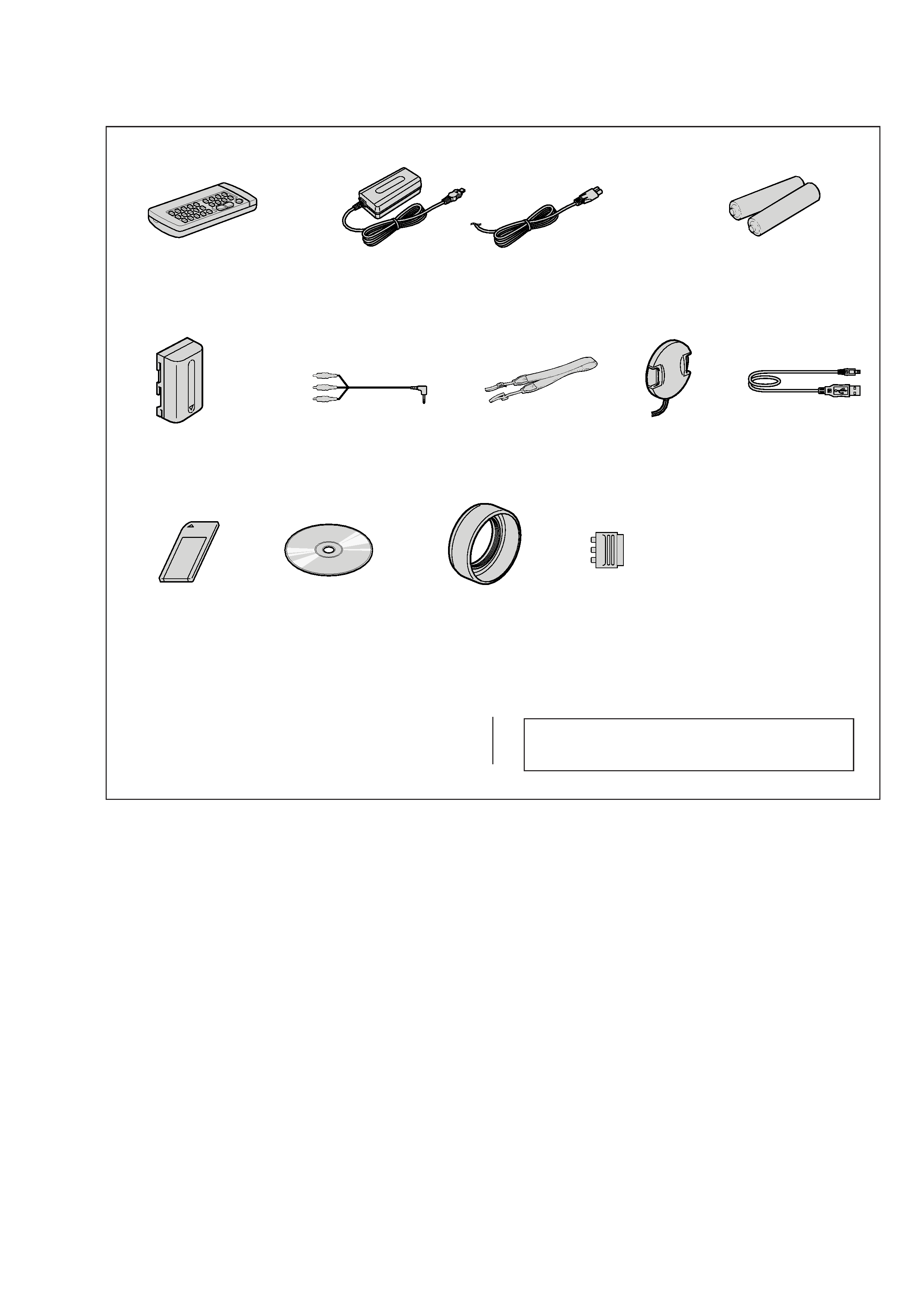
Checking supplied accessories.
Make sure that the following accessories are supplied with your camcorder.
Other accessories
3-067-862-11 MANUAL, INSTRUCTION (ENGLISH/RUSSIAN)
3-067-862-21 MANUAL, INSTRUCTION (FRENCH/GERMAN)(AEP)
3-067-862-31 MANUAL, INSTRUCTION (ENGLISH/DUTCH)(AEP)
Note :
The components identified by mark 0 or dotted
line with mark 0 are critical for safety.
Replace only with part number specified.
Wireless Remote Commander (1)
RMT-811
1-475-950-21
AC-L10A
AC power adaptor (1)
0 1-475-599-11
Size AA (R6) battery for
Remote Commander (2)
(not supplied)
A/V connecting cable (1.5m) (1)
1-765-080-11
21-pin adaptor (1)
1-573-291-11
Lens cap (1)
X-3949-944-01
NP-FM50 battery pack (1)
(not supplied)
Shoulder strap (1)
3-987-015-01
USB cable (1)
1-757-293-11
Memory Stick (1)
(MSA-4A)
A-7033-740-A
CD-ROM
(SPVD-004 USB Driver)(1)
3-066-676-01
Power cord (Main lead)(1) (AEP model)
0 1-769-608-11
Power cord (Main lead)(1) (UK model)
0 1-783-374-11
Lens hood (1)
3-063-515-01

-- 4 --
TABLE OF CONTENTS
SERVICE NOTE
1.
POWER SUPPLY DURING REPAIRS ····························· 5
2.
TO TAKE OUT A CASSETTE WHEN NOT EJECT
(FORCE EJECT) ································································ 5
3.
DISCHARGING OF THE FLASHLIGHT POWER
SUPPLY CAPACITOR ······················································ 6
3-1.
PREPARING THE SHORT JIG ········································· 6
3-2.
DISCHARGING THE CAPACITOR ································· 6
SELF-DIAGNOSIS FUNCTION
1.
SELF-DIAGNOSIS FUNCTION ······································· 7
2.
SELF-DIAGNOSIS DISPLAY ·········································· 7
3.
SERVICE MODE DISPLAY ············································· 7
3-1.
Display Method ·································································· 7
3-2.
Switching of Backup No. ··················································· 7
3-3.
End of Display ···································································· 7
4.
SELF-DIAGNOSIS CODE TABLE ··································· 8
1.
MAIN PARTS
1.
ORNAMENTAL PARTS ···················································· 9
2.
DISASSEMBLY ······························································· 10
2-1.
LCD SECTION (PD-145 BOARD) ································· 11
2-2.
EVF SECTION (LB-072 BOARD) ·································· 12
2-3.
FRONT PANEL SECTION
(MI-043, ML-023, SE-121 BOARDS) ····························· 13
2-4.
CABINET (R) SECTION (CK-102 BOARD) ················· 14
2-5.
BT PANEL SECTION, EVF SECTION ·························· 14
2-6.
VC-264P BOARD, MECHANISM DECK ······················ 15
2-7.
LENS SECTION (JK-207 BOARD) ································ 15
2-8.
CONTROL SWITCH BLOCK (FK-1800),
CONTROL SWITCH BLOCK (PS-1800) ······················· 16
2-9.
FLASH UNIT ··································································· 17
2-10. PO-006 BOARD, HINGE ASSEMBLY ··························· 17
2-11. GRIP BELT ······································································ 18
3.
REPAIR PARTS LIST ······················································ 19
3-1.
EXPLODED VIEWS ······················································· 19
3-1-1. OVERALL SECTION ······················································ 19
3-1-2. CABINET (R) SECTION ················································ 20
3-1-3. LCD SECTION ································································ 21
3-1-4. CABINET (L) SECTION-1 ············································· 22
3-1-5. CABINET (L) SECTION-2 ············································· 23
3-1-6. LENS, EVF SECTION ····················································· 24
2.
GENERAL
Main Features ············································································· 25
Quick Start Guide ······································································ 25
Getting started
Using this manual ··································································· 26
Checking supplied accessories ··············································· 26
Step 1 Preparing the power supply ········································· 26
Installing the battery pack ···················································· 26
Charging the battery pack ···················································· 27
Connecting to a wall socket ················································· 27
Step 2 Setting the date and time ············································· 28
Step 3 Inserting a cassette ······················································· 28
Recording Basics
Recording a picture ································································· 29
Shooting backlit subjects BACK LIGHT ························· 30
Shooting in the dark NightShot/Super NightShot ············ 31
Self-timer recording ····························································· 31
Checking the recording END SEARCH/EDITSEARCH/
Rec Review ·········································································· 31
Playback Basics
Playing back a tape ································································· 32
Viewing the recording on TV ················································· 33
Advanced Recording Operations
Recording a still image on a tape Tape Photo recording ····· 34
Adjusting the white balance manually ···································· 36
Using the wide mode ······························································ 36
Using the fader function ························································· 37
Using special effects Picture effect ······································ 37
Using special effects Digital effect ······································ 38
Using the PROGRAM AE function ········································ 38
Adjusting the exposure manually ··········································· 39
Focusing manually ·································································· 39
Interval recording ···································································· 40
Frame by frame recording Cut recording ···························· 41
Advanced Playback Operation
Playing back a tape with picture effects ································· 41
Playing back a tape with digital effects ·································· 41
Enlarging images recorded on tapes Tape PB ZOOM ········· 42
Quickly locating a scene using the zero set memory function ····· 42
Searching the boundaries of recorded tape by title
Title search ········································································ 43
Searching a recording by date Date search ·························· 43
Searching for a photo Photo search/Photo scan ··················· 44
Editing
Dubbing a tape ········································································ 44
Dubbing only desired scenes Digital program editing ········ 45
Using with analog video unit and personal computer
Signal convert function ····················································· 49
Recording video or TV programmes ······································ 49
Inserting a scene from a VCR Insert editing ························ 50
Audio dubbing ········································································ 51
Superimposing a title ······························································ 52
Making your own titles ··························································· 53
Labelling a cassette ································································· 54
Customising Your Camcorder
Changing the menu settings ···················································· 54
"Memory Stick" operations
Using a "Memory Stick" introduction ·································· 56
Recording still images on "Memory Stick"s
Memory Photo recording ·················································· 59
Recording an image from a tape as a still image ···················· 61
Recording moving pictures on "Memory Stick"s
MPEG movie recording ···················································· 61
Recording a picture from a tape as a moving picture ············· 62
Superimposing a still picture in a "Memory Stick"
on a moving picture MEMORY MIX ······························· 63
Copying still images from a tape Photo save ······················· 64
Viewing a still picture Memory photo playback ·················· 64
Viewing a moving picture MPEG movie playback ············· 65
Viewing images using your computer ···································· 66
Copying the image recorded on "Memory Stick"s to tapes ······· 67
Enlarging still images recorded on "Memory Stick"s
Memory PB ZOOM ·························································· 68
Playing back images in a continuous loop SLIDE SHOW ······· 68
Preventing accidental erasure Image protection ·················· 69
Deleting images ······································································ 69
Writing a print mark PRINT MARK ··································· 70
Using the printer (optional) ···················································· 71
Troubleshooting
Types of trouble and their solutions ········································ 71
Self-diagnosis display ····························································· 73
Warning indicators and messages ··········································· 73
Additional Information
Usable cassettes ······································································ 73
About the "InfoLITHIUM" battery pack ································ 74
About i.LINK ·········································································· 75
Using your camcorder abroad ················································· 75
Maintenance information and precautions ······························ 75
Quick Reference
Identifying the parts and controls ··········································· 77
-- 5 --
1.
POWER SUPPLY DURING REPAIRS
In this unit, about 10 seconds after power is supplied to the battery terminal using the regulated power supply (8.4V), the power is shut off so
that the unit cannot operate.
This following two methods are available to prevent this. Take note of which to use during repairs.
Method 1.
Use the AC power adaptor (AC-L10, AC-VQ800 etc.).
Method 2.
Connect the servicing remote commander RM-95 (J-6082-053-B) to the LANC jack, and set the commander switch to the "ADJ" side.
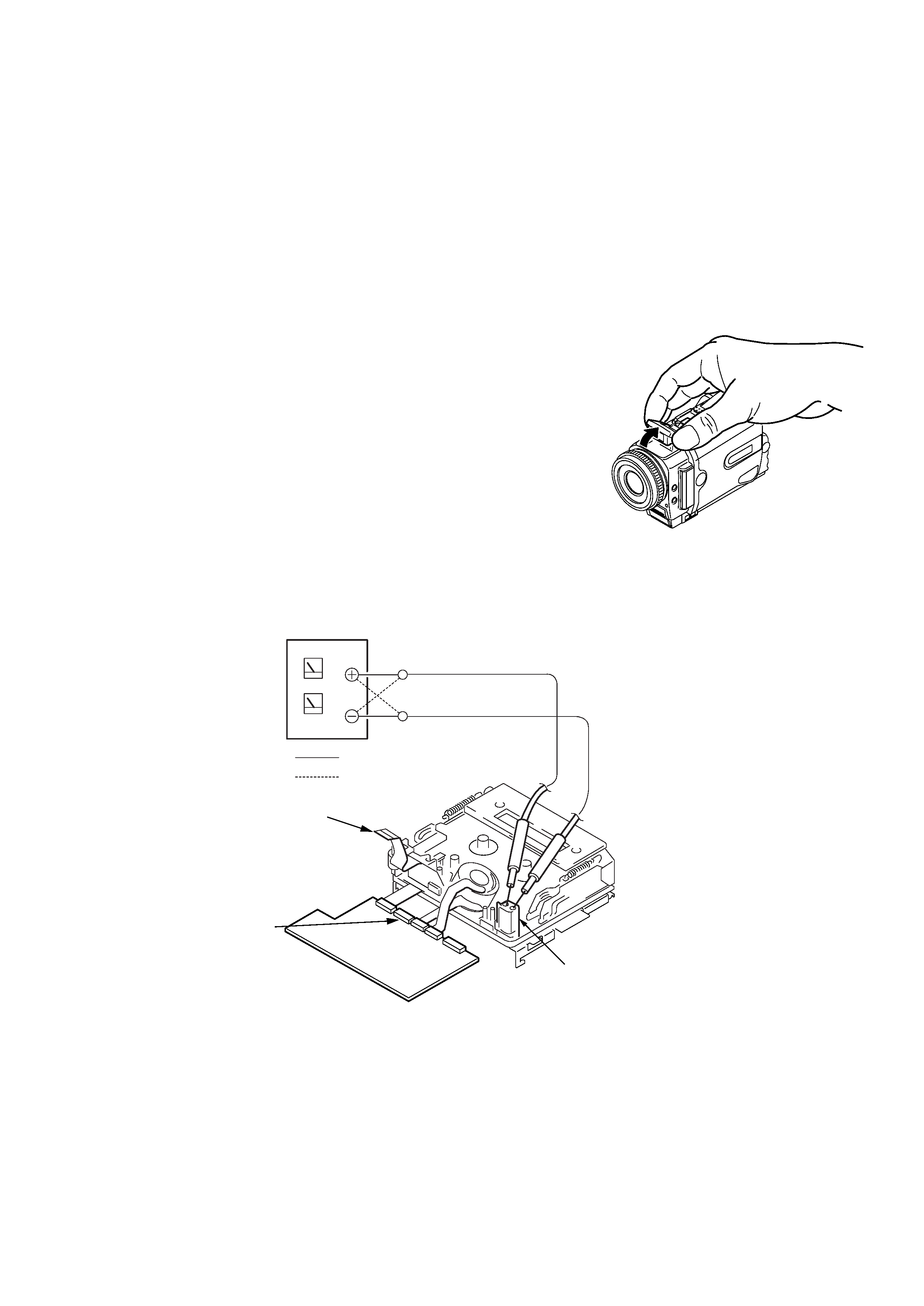
2.
TO TAKE OUT A CASSETTE WHEN NOT EJECT
(FORCE EJECT)
1
Open the flash.
(If the flash cannot be opened i the position as shown, remove the top cabinet reffering
to section 2-4 and open the flash.)
2
Refer to 2-3 to remove the front panel assembly.
3
Refer to 2-4 to remove the upper cabinet assembly.
4
Refer to 2-4 to remove the cabinet (R) assembly.
5
Refer to 2-5 to remove the battery panel section.
6
Refer to 2-5 to remove the VC heat sink and EVF section.
7
Open the VC-264P board.
8
Refer to 2-6 to remove the three screws with which the MD frame assembly is fixed.
9
Remove the mechanism deck and VC-264P board.
0
Disconnect CN006 (27P, 0.3mm) of VC-264P board.
qa
Supply +4.5V from the DC power supply to the loading motor and unload with a pressing the cassette compartment.
SERVICE NOTE
VC-264P
board
CN006
: Unloading
: Loading
Loading motor
DC power supply
(+4.5Vdc)
Disconnect from CN006 (27P)
of VC-264P board