SERVICE MANUAL
·For ADJUSTMENTS (SECTION 6), refer to SERVICE MANUAL, ADJ (987621151.pdf).
·For INSTRUCTION MANUAL, refer to SERVICE MANUAL, LEVEL 1 (987621141.pdf).
·For MECHANISM ADJUSTMENTS, refer to the "8mm Video MECHANICAL ADJUSTMENT MANUAL IX
M2000 MECHANISM " (9-929-861-11).
· Reference No. search on printed wiring boards is available.
·Table for differences of function of each model.
·When the machine needs to be repaired, make sure to follow the items of "LCD TYPE CHECK".
· HELP: Sheet attachment positions and procedures of processing the flexible boards/harnesses are shown.
Link
SERVICE NOTE
DISASSEMBLY
BLOCK DIAGRAMS
FRAME SCHEMATIC DIAGRAMS
SCHEMATIC DIAGRAMS
PRINTED WIRING BOARDS
REPAIR PARTS LIST
SPECIFICATIONS
SERVICE NOTE
DISASSEMBLY
BLOCK DIAGRAMS
FRAME SCHEMATIC DIAGRAMS
SCHEMATIC DIAGRAMS
PRINTED WIRING BOARDS
REPAIR PARTS LIST
SPECIFICATIONS
Link
Revision History
Revision History
Ver 1.0 2003. 02
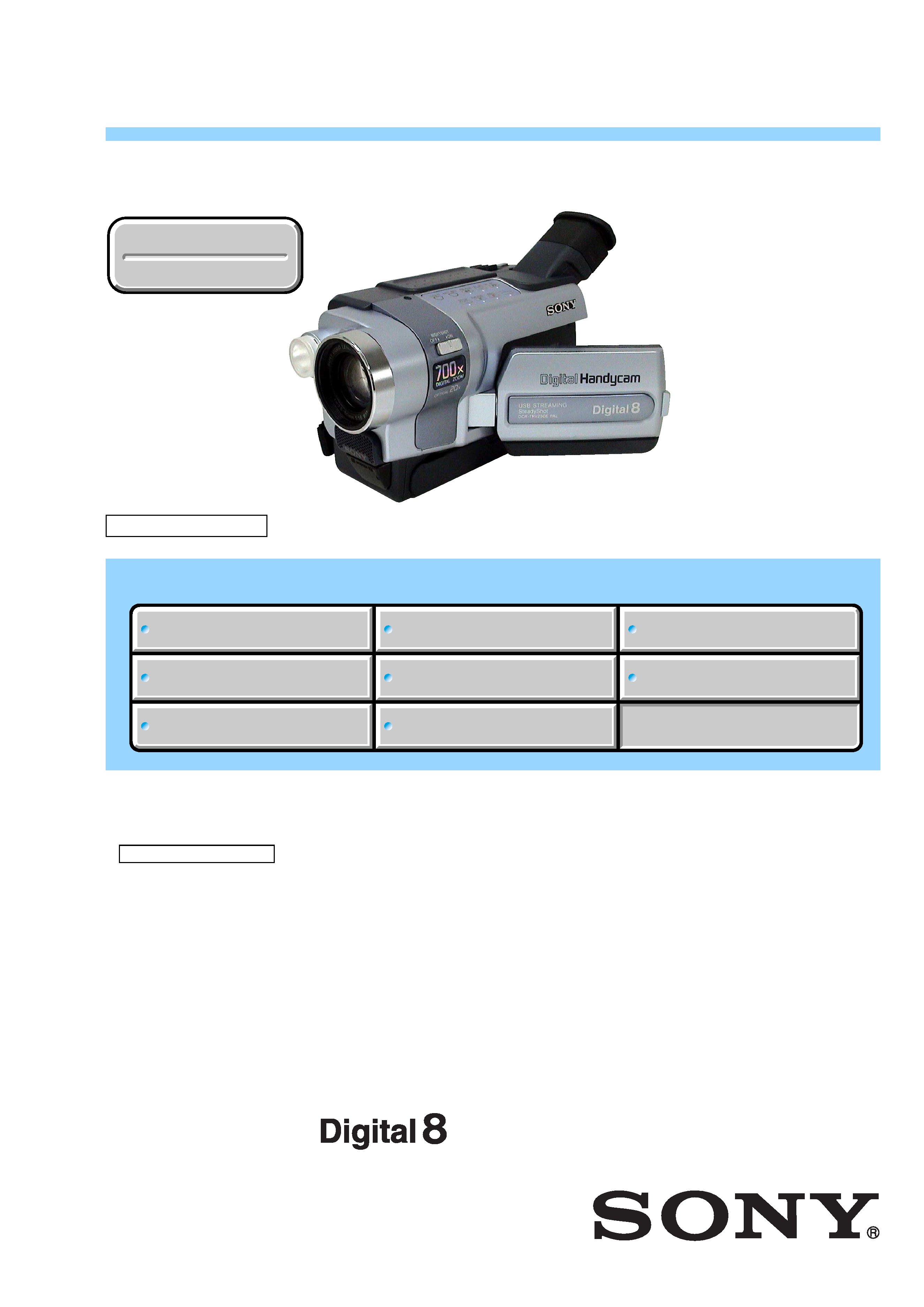
M2200 MECHANISM
Photo: DCR-TRV250E
DCR-TRV145E/TRV147E/TRV245E/TRV250E
RMT-814
AEP Model
UK Model
East European Model
North European Model
DCR-TRV145E/TRV147E/TRV245E/
TRV250E
E Model
DCR-TRV147E/TRV250E
Australian Model
DCR-TRV147E/TRV250E
Chinese Model
DCR-TRV250E
Tourist Model
DCR-TRV250E
DIGITAL VIDEO CAMERA RECORDER

-- 2 --
DCR-TRV145E/TRV147E/TRV245E/TRV250E
SPECIFICATIONS
COVER
COVER
Viewfinder
Electric Viewfinder (monochrome)
Image device
3 mm (1/6 type) CCD
(Charge Coupled Device)
Gross: Approx. 540 000 pixels
Effective: Approx. 350 000 pixels
Video camera
recorder
System
Video recording system
2 rotary heads
Helical scanning system
Audio recording system
Rotary heads, PCM system
Quantization: 12 bits (Fs 32 kHz,
stereo 1, stereo 2), 16 bits
(Fs 48 kHz, stereo)
Video signal
PAL colour, CCIR standards
Usable cassette
8 mm video format cassette
Recording/playback time
(using 90 min. Hi8/Digital8 video
cassette)
SP mode: 1 hour
LP mode: 1 hour and 30 minutes
Fastforward/rewind time
(using 90 min. Hi8/Digital8 video
cassette)
Approx. 5 min.
Input/output
connectors
S
Output
video jack
4-pin mini DIN
Luminance signal: 1 Vp-p,
75 (ohms), unbalanced
Chrominance signal: 0.3 Vp-p,
75 (ohms), unbalanced
Audio/Video
Output
jack
AV MINIJACK,
VIDEO:
1 Vp-p, 75 (ohms),
unbalanced, sync negative
AUDIO:
327 mV, (at output impedance more
than 47 k (kilohms))
Output impedance with less than
2.2 k (kilohms)
Stereo minijack (ø 3.5 mm)
LCD screen
Picture
6.2 cm (2.5 type)
50.3 × 37.4 mm
(2 × 1 1/2 in.)
Total dot number
123 200 (560 × 220)
General
Power requirements
7.2 V (Recahrgeable battery pack)
8.4 V (AC adaptor)
Average power consumption
(when using the battery pack)
During camera recording using
LCD
3.5 W
Viewfinder
2.7 W
Operating temperature
0 °C to 40 °C (32 °F to 104 °F)
Recommended charging
temperature
10 °C to 30 °C (50 °F to 86 °F)
Storage temperature
20 °C to +60 °C (4 °F to +140 °F)
Dimensions (approx.)
89 × 101 × 199 mm
(3 5/8 × 4 × 7 7/8 in.) (w/h/d)
Mass (approx.)
810 g (1 lb 12 oz)
main unit only
950 g (2 lb 1 oz)
including the rechargeable battery
pack NP-FM30, Hi8/Digital8 cassette,
lens cap and shoulder strap
AC adaptor
Power requirements
100 - 240 V AC, 50/60 Hz
Power consumption
18 W
Current consumption
0.35 0.18 A
Output voltage
DC OUT: 8.4 V, 1.5 A in the
operating mode
Operating temperature
0 °C to 40 °C (32 °F to 104 °F)
Storage temperature
20 °C to +60 °C (4 °F to +140 °F)
Dimensions (approx.)
56 × 31 × 100 mm
(2 1/4 × 1 1/4 × 4 in.) (w/h/d)
excluding projecting parts
Mass (approx.)
190 g (6.7 oz)
excluding mains lead
Recargeable
battery pack
Maximum output voltage
DC 8.4 V
Output voltage
DC 7.2 V
Capacity
5.0 Wh (700 mAh)
Operating temperature
0 °C to 40 °C (32 °F to 104 °F)
Dimensions (approx.)
38.2 × 20.5 × 55.6 mm
(1 9/16 × 13/16 × 2 1/4 in.)
(w/h/d)
Mass (approx.)
65 g (2.3 oz)
Type
Lithium ion
Design and specifications are
subject to change without notice.
DV jack
DCR-TRV147E/TRV250E:
Input/Output
4-pin connector
DCR-TRV145E/TRV245E:
Output
4-pin connector
DCR-TRV245E/TRV250E:
Mini-B
USB jack
Lens
Combined power zoom lens
Filter
DCR-TRV145E/TRV147E:
diameter 37 mm (1 7/16 in.)
20× (Optical), 560× (Digital)
DCR-TRV245E/TRV250E:
20× (Optical), 700× (Digital)
Focal length
f=2.5 50 mm (1/8 - 2 in.)
When converted to a 35 mm
still camera
f=42 840 mm (1 11/16 - 33 1/8 in.)
Colour temperature
Auto
Minimum illumination
4 lx (lux) (F 1.6)
0 lx (lux) (in the NightShot mode)*
*Objects unable to be seen due to
the dark can be shot with infrared
lighting.
SERIES
TM
-- 3 --
DCR-TRV145E/TRV147E/TRV245E/TRV250E
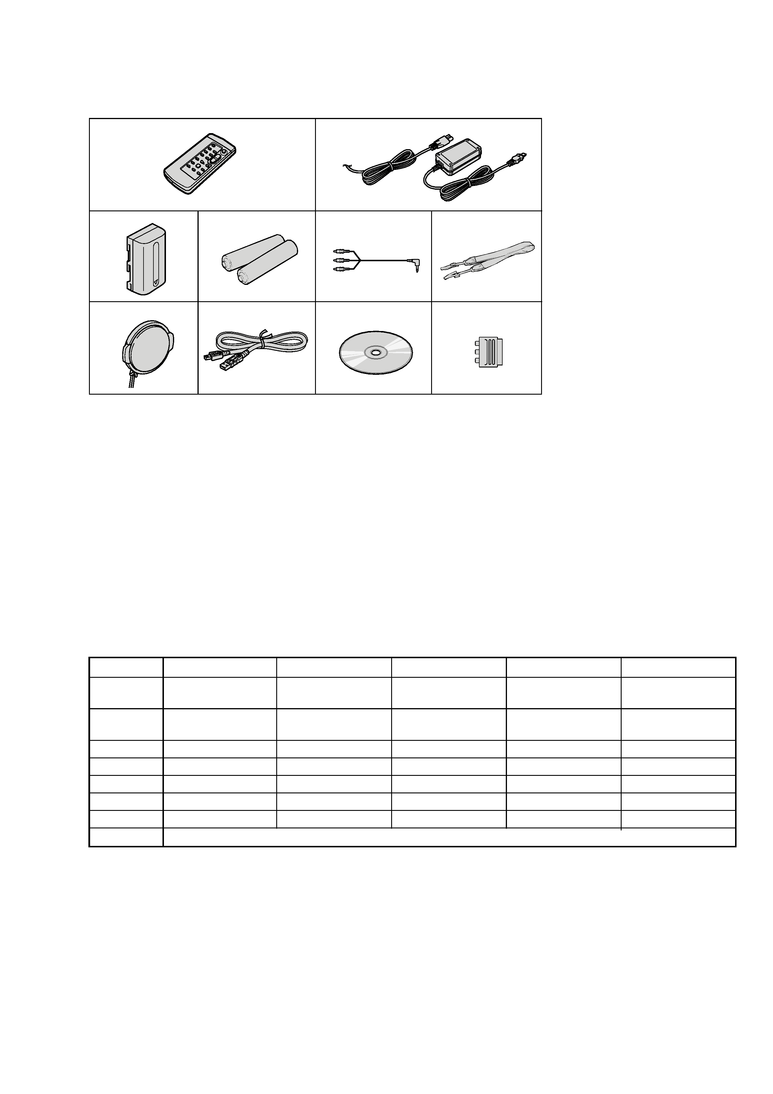
Supplied accessories
1
Wireless Remote Commander (1)
2
AC-L15A/L15B AC Adaptor (1), Power
cord (1)
3
NP-FM30 Rechargeable Battery Pack
(1)
DCR-TRV245E/TRV250E
DCR-TRV245E/TRV250E
DCR-TRV245E/TRV250E
AEP, UK, EE, NE
DCR-TRV245E/TRV250E
4
Size AA (R6) battery for Remote
Commander (2)
5
A/V connecting cable (1)
6
Shoulder strap (1)
7
Lens cap (1)
8
USB cable (1)
9
CD-ROM (SPVD-010 USB Driver) (1)
0
21-pin adaptor (1)
1
2
3
4
7
89
q;
6
5
·Abbreviation
AUS: Australian model
CH
: Chinese model
EE
: East European model
JE
: Tourist model
NE
: North European model
Table for differences of function
Model
DCR-TRV145E
DCR-TRV147E
DCR-TRV245E
DCR-TRV250E
Remark
Destination
AEP, UK, EE, NE
AEP, UK, EE, NE,
AEP, UK, EE, NE
AEP, UK, EE, NE,
E, AUS
E, AUS, CH, JE
Remote
aa
commander
Digital zoom
560x
560x
700x
700x
Steady shot
aa
VTR Rec
a
aa: with REC button
DV jack
DV OUT
DV IN/OUT
DV OUT
DV IN/OUT
USB jack
aa
LCD type
Please refer to page 1-2 to discriminate the type of LCD (TYPE C or TYPE S).

-- 4 --
DCR-TRV145E/TRV147E/TRV245E/TRV250E
SAFETY-RELATED COMPONENT WARNING!!
COMPONENTS IDENTIFIED BY MARK 0 OR DOTTED LINE WITH
MARK 0 ON THE SCHEMATIC DIAGRAMS AND IN THE PARTS
LIST ARE CRITICAL TO SAFE OPERATION. REPLACE THESE
COMPONENTS WITH SONY PARTS WHOSE PART NUMBERS
APPEAR AS SHOWN IN THIS MANUAL OR IN SUPPLEMENTS
PUBLISHED BY SONY.
1.
Check the area of your repair for unsoldered or poorly-soldered
connections. Check the entire board surface for solder splashes
and bridges.
2.
Check the interboard wiring to ensure that no wires are
"pinched" or contact high-wattage resistors.
3.
Look for unauthorized replacement parts, particularly
transistors, that were installed during a previous repair. Point
them out to the customer and recommend their replacement.
4.
Look for parts which, through functioning, show obvious signs
of deterioration. Point them out to the customer and
recommend their replacement.
5.
Check the B+ voltage to see it is at the values specified.
6.
Flexible Circuit Board Repairing
·Keep the temperature of the soldering iron around 270°C
during repairing.
· Do not touch the soldering iron on the same conductor of the
circuit board (within 3 times).
· Be careful not to apply force on the conductor when soldering
or unsoldering.
Unleaded solder
Boards requiring use of unleaded solder are printed with the lead-
free mark (LF) indicating the solder contains no lead.
(Caution: Some printed circuit boards may not come printed with
the lead free mark due to their particular size.)
: LEAD FREE MARK
Unleaded solder has the following characteristics.
· Unleaded solder melts at a temperature about 40
°C higher than
ordinary solder.
Ordinary soldering irons can be used but the iron tip has to be
applied to the solder joint for a slightly longer time.
Soldering irons using a temperature regulator should be set to
about 350
°C.
Caution: The printed pattern (copper foil) may peel away if the
heated tip is applied for too long, so be careful!
· Strong viscosity
Unleaded solder is more viscous (sticky, less prone to flow) than
ordinary solder so use caution not to let solder bridges occur such
as on IC pins, etc.
· Usable with ordinary solder
It is best to use only unleaded solder but unleaded solder may
also be added to ordinary solder.
SAFETY CHECK-OUT
After correcting the original service problem, perform the following
safety checks before releasing the set to the customer.

-- 5 --
DCR-TRV145E/TRV147E/TRV245E/TRV250E
TABLE OF CONTENTS
1.
SERVICE NOTE
1-1.
Note for Repair ································································ 1-1
1-2.
Power Supply During Repairs ········································· 1-1
1-3.
To Take Out a Cassette when not Eject (Force Eject) ····· 1-2
1-4.
LCD Type Check ····························································· 1-2
1-5.
Self-diagnosis Function ··················································· 1-3
1-5-1. Self-diagnosis Function ··················································· 1-3
1-5-2. Self-diagnosis Display ····················································· 1-3
1-5-3. Service Mode Display ····················································· 1-3
1-5-4. Self-diagnosis Code Table ··············································· 1-4
2.
DISASSEMBLY
Connection of Equipment ················································ 2-2
2-1.
Video Light ······································································ 2-3
2-2.
PD-180 Board ·································································· 2-4
2-3.
LCD Module ···································································· 2-5
Service Position to Check PD-180 Board ······················· 2-5
2-4.
Control Switch Block (PR-3000) ···································· 2-6
2-5.
VF Lens (B) Assembly ···················································· 2-7
2-6.
LB-090 Board ·································································· 2-8
Service Position to Check LB-090 Board ······················· 2-8
2-7.
Cabinet (L) Assembly ······················································ 2-9
2-8.
F Panel Block Assembly ················································ 2-10
Service Position to Check SI-035 Board ······················· 2-11
2-9.
SI-035 Board ································································· 2-12
2-10. Front Ring ······································································ 2-12
2-11. Cabinet (R) Block Assembly ········································· 2-13
Service Position to Check the Camera Section ············· 2-13
2-12. Control Switch Block (CF-3000) ·································· 2-14
2-13. Hinge Assembly ···························································· 2-15
2-14. Control Switch Block (FK-3000) ·································· 2-16
2-15. EVF Block Assembly ···················································· 2-16
Service Position to Check VC-304 Board (Side A) ······· 2-17
2-16. Battery Panel Block Assembly ······································ 2-18
2-17. Control Switch Block (SS-3000) ··································· 2-19
2-18. Lens Block Assembly ···················································· 2-19
2-19. FP-577 Flexible Board ·················································· 2-20
2-20. Cabinet (L) Section ······················································· 2-21
2-21. VC-304 Board ······························································· 2-21
Service Position to Check VC-304 Board (Side B) ······· 2-22
Service Position to Check the Mechanism Deck ··········· 2-23
2-22. Mechanism Deck Block ················································ 2-24
2-23. Circuit Boards Location ················································ 2-25
2-24. Flexible Boards Location ·············································· 2-26
3.
BLOCK DIAGRAMS
3-1.
Overall Block Diagram (1/5) ··········································· 3-1
3-2.
Overall Block Diagram (2/5) ··········································· 3-3
3-3.
Overall Block Diagram (3/5) ··········································· 3-5
3-4.
Overall Block Diagram (4/5) ··········································· 3-7
3-5.
Overall Block Diagram (5/5) ··········································· 3-9
3-6.
Power Block Diagram (1/2) ··········································· 3-11
3-7.
Power Block Diagram (2/2) ··········································· 3-13
Section
Title
Page
Section
Title
Page
4.
PRINTED WIRING BOARDS AND
SCHEMATIC DIAGRAMS
4-1.
Frame Schematic Diagrams
Frame Schematic Diagram (1/2) ····································· 4-1
Frame Schematic Diagram (2/2) ····································· 4-3
4-2.
Schematic Diagrams ························································ 4-5
CD-418 (CCD IMAGER) ················································ 4-7
VC-304 (1/12)
(A/D CONVERTER, TIMING GENERATOR) ·············· 4-9
VC-304 (2/12) (DV SIGNAL PROCESS) ···················· 4-11
VC-304 (3/12) (DV INTERFACE, VIDEO OUT) ········ 4-13
VC-304 (4/12) (LENS DRIVE) ···································· 4-15
VC-304 (5/12) (REC/PB AMP) ···································· 4-17
VC-304 (6/12) (SERVO) ··············································· 4-19
VC-304 (7/12) (CAMERA/MECHA CONTROL) ······· 4-21
VC-304 (8/12) (HI CONTROL) ···································· 4-23
VC-304 (9/12) (EVF DRIVE) ······································· 4-25
VC-304 (10/12) (AUDIO PROCESS) ··························· 4-27
VC-304 (11/12) (DC CONTROL) ································ 4-29
VC-304 (12/12) (CONNECTOR) ································· 4-31
PD-180 (1/2)
(RGB DRIVE, TIMING GENERATOR) ······················ 4-33
PD-180 (2/2) (BACKLIGHT DRIVE) ·························· 4-35
LB-090 (EVF, EVF BACKLIGHT) ······························ 4-37
SI-035 (STEADYSHOT, MIC),
FP-569 FLEXIBLE ······················································· 4-39
FP-577 FLEXIBLE ······················································· 4-41
LS-057 (S/T REEL SENSOR), FP-228, FP-299,
FP-300, FP-301, FP-302 FLEXIBLE ···························· 4-42
CF-3000, FK-3000 (CONTROL SWITCH BLOCK) ··· 4-43
SS-3000, PR-3000 (CONTROL SWITCH BLOCK) ···· 4-45
4-3.
Printed Wiring Boards ··················································· 4-47
CD-418 ·········································································· 4-49
VC-304 ·········································································· 4-51
PD-180 ··········································································· 4-55
LB-090 ··········································································· 4-59
SI-035 ············································································ 4-61
LS-057, FP-228, FP-299, FP-300, FP-301,
FP-302, FP-569, FP-577 FLEXIBLE ···························· 4-63
4-4.
Waveforms ····································································· 4-65
4-5.
Mounted Parts Location ················································ 4-72
5.
REPAIR PARTS LIST
5-1.
Exploded Views ···························································· 5-2
5-1-1. Overall Assembly ·························································· 5-2
5-1-2. F Panel Block Assembly ··············································· 5-3
5-1-3. Lens Block Assembly ··················································· 5-4
5-1-4. LCD Block Assembly ··················································· 5-5
5-1-5. Cabinet (R) Block Assembly ········································ 5-6
5-1-6. EVF Block Assembly ···················································· 5-7
5-1-7. Battery Panel Block Assembly ······································ 5-8
5-1-8. MD Frame Block ·························································· 5-9
5-1-9. Cassette Compartment Assembly, Drum Assembly ··· 5-10
5-1-10. LS Chassis Block Assembly ······································· 5-11
5-1-11. Mechanism Chassis Block Assembly-1 ······················ 5-12
5-1-12. Mechanism Chassis Block Assembly-2 ······················ 5-13
5-2.
Electrical Parts List ····················································· 5-14