SERVICE MANUAL
Viewfinder
Electric Viewfinder (monochrome)
Image device
4.5 mm (1/4 type) CCD
(Charge Coupled Device)
DCR-TRV140/TRV140M:
Approx. 460 000 pixels
(Effective: Approx. 290 000 pixels)
DCR-TRV140E:
Approx. 540 000 pixels
(Effective: Approx. 350 000 pixels)
Lens
Combined power zoom lens
Filter diameter 37 mm (1 7/16 in.)
20
× (Optical), 560× (Digital)
Focal length
3.6 - 72 mm (5/32 - 2 7/8 in.)
When converted to a 35 mm
still camera
41 - 820 mm (1 5/8 - 32 3/8 in.)
Colour temperature
Auto
Minimum illumination
1 lx (lux) (F 1.4)
0 lx (lux) (in the NightShot mode)*
* Objects unable to be seen due to
the dark can be shot with infrared
lighting.
Video camera
recorder
System
Video recording system
2 rotary heads
Helical scanning system
Audio recording system
Rotary heads, PCM system
Quantization: 12 bits (Fs 32 kHz,
stereo 1, stereo 2), 16 bits
(Fs 48 kHz, stereo)
Video signal
DCR-TRV140/TRV140M:
NTSC color, EIA standards
DCR-TRV140E:
PAL colour, CCIR standards
Recommended cassette
Hi8/Digital8 video cassette
Recording/playback time (using
90 min. Hi8/Digital 8 video
cassette)
SP mode: 1 hour
LP mode: 1 hour and 30 minutes
Fastforward/rewind time (using
90 min. Hi8/Digital 8 video
cassette)
Approx. 5 min.
Input/output
connectors
S video output
DCR-TRV140/TRV140M:
4-pin mini DIN
Luminance signal: 1 Vp-p,
75
(ohms), unbalanced
Chrominance signal: 0.286 Vp-p,
75
(ohms), unbalanced
DCR-TRV140E:
4-pin mini DIN
Luminance signal: 1 Vp-p,
75
(ohms), unbalanced
Chrominance signal: 0.3 Vp-p,
75
(ohms), unbalanced
Audio/Video output
AV MINIJACK, 1 Vp-p, 75
(ohms), unbalanced, sync negative
327 mV, (at output impedance more
than 47 k
(kilohms))
Output impedance with less than
2.2 k
(kilohms)/Stereo minijack
(ø 3.5 mm)
DCR-TRV140/TRV140E:
E, HK, AUS, CH, JE/TRV140M
DV input/output
4-pin connector
DCR-TRV140E:
AEP, UK, EE, NE, RU
DV output
4-pin connector
USB jack
Mini-B
LCD screen
Picture
6.2 cm (2.5 type)
50.3
× 37.4 mm
(2
× 1 1/2 in.)
Total dot number
61 600 (280
× 220)
General
Power requirements
7.2 V (battery pack)
8.4 V (AC power adaptor)
Average power consumption
(when using the battery pack)
During camera recording using
LCD
3.5 W
Viewfinder
2.8 W
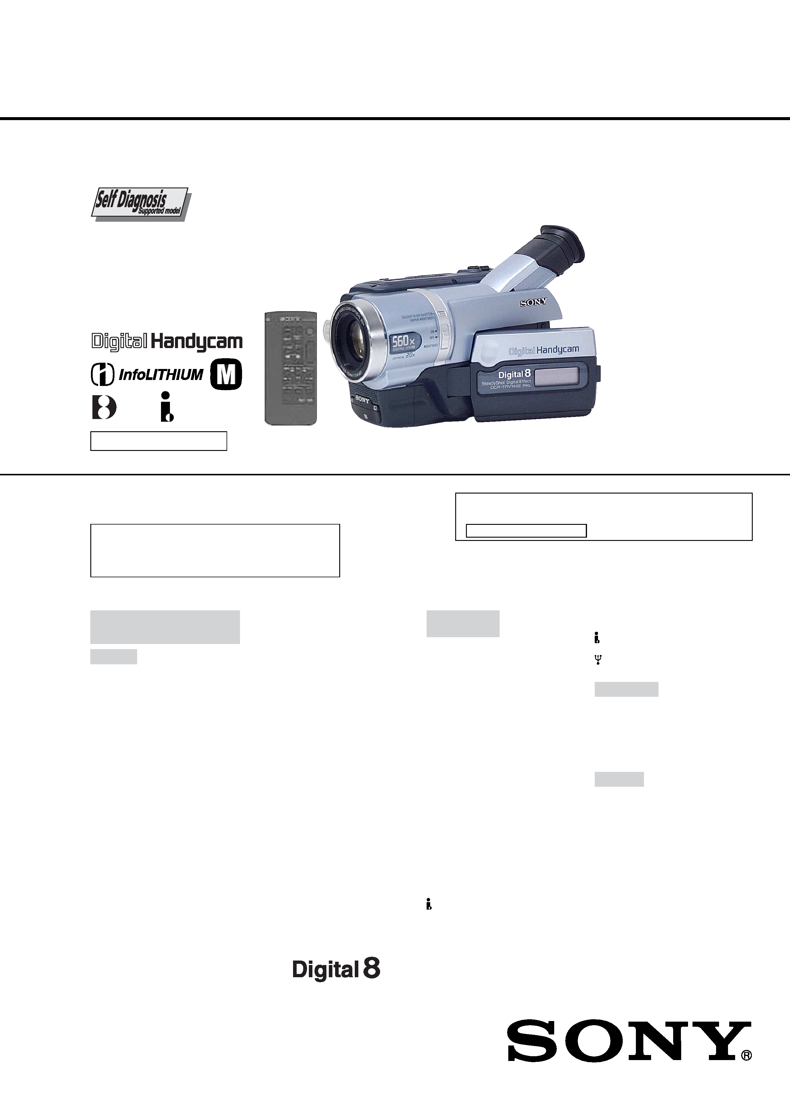
DIGITAL VIDEO CAMERA RECORDER
SPECIFICATIONS
RMT-814
DCR-TRV140/TRV140E/TRV140M
US Model
DCR-TRV140/TRV140M
Canadian Model
DCR-TRV140
AEP Model
UK Model
East European Model
North European Model
Russian Model
DCR-TRV140E
E Model
Hong Kong Model
DCR-TRV140/TRV140E
Brazilian Model
DCR-TRV140
Australian Model
Chinese Model
DCR-TRV140E
Tourist Model
DCR-TRV140/TRV140E
M2000 MECHANISM
Continued on next page
NTSC MODEL : DCR-TRV140/TRV140M
PAL MODEL
: DCR-TRV140E
Photo: DCR-TRV140E
Ver 1.1 2003. 06
For MECHANISM ADJUSTMENT, refer to the "8mm
Video MECHANICAL ADJUSTMENT MANUAL
IX
M2000 MECHANISM " (9-929-861-11).
When the machine needs to be repaired,
please refer to page 7 to discriminate the
type of LCD.

2
DCR-TRV140/TRV140E/TRV140M
1. Check the area of your repair for unsoldered or poorly-sol-
dered connections. Check the entire board surface for solder
splashes and bridges.
2. Check the interboard wiring to ensure that no wires are
"pinched" or contact high-wattage resistors.
3. Look for unauthorized replacement parts, particularly transis-
tors, that were installed during a previous repair. Point them
out to the customer and recommend their replacement.
4. Look for parts which, though functioning, show obvious signs
of deterioration. Point them out to the customer and recom-
mend their replacement.
5. Check the B+ voltage to see it is at the values specified.
6. Flexible Circuit Board Repairing
·
Keep the temperature of the soldering iron around 270 °C
during repairing.
·
Do not touch the soldering iron on the same conductor of
the circuit board (within 3 times).
·
Be careful not to apply force on the conductor when sol-
dering or unsoldering.
SAFETY CHECK-OUT
After correcting the original service problem, perform the following
safety checks before releasing the set to the customer.
ATTENTION AU COMPOSANT AYANT RAPPORT
À LA SÉCURITÉ!
LES COMPOSANTS IDENTIFIÉS PAR UNE MARQUE 0
SUR LES DIAGRAMMES SCHÉMATIQUES ET LA LISTE
DES PIÈCES SONT CRITIQUES POUR LA SÉCURITÉ
DE FONCTIONNEMENT. NE REMPLACER CES COM-
POSANTS QUE PAR DES PIÈCES SONY DONT LES
NUMÉROS SONT DONNÉS DANS CE MANUEL OU
DANS LES SUPPLÉMENTS PUBLIÉS PAR SONY.
SAFETY-RELATED COMPONENT WARNING!!
COMPONENTS IDENTIFIED BY MARK 0 OR DOTTED
LINE WITH MARK 0 ON THE SCHEMATIC DIAGRAMS
AND IN THE PARTS LIST ARE CRITICAL TO SAFE
OPERATION. REPLACE THESE COMPONENTS WITH
SONY PARTS WHOSE PART NUMBERS APPEAR AS
SHOWN IN THIS MANUAL OR IN SUPPLEMENTS PUB-
LISHED BY SONY.
UNLEADED SOLDER
Boards requiring use of unleaded solder are printed with the lead-
free mark (LF) indicating the solder contains no lead.
(Caution: Some printed circuit boards may not come printed with
the lead free mark due to their particular size)
: LEAD FREE MARK
Unleaded solder has the following characteristics.
· Unleaded solder melts at a temperature about 40 °C higher than
ordinary solder.
Ordinary soldering irons can be used but the iron tip has to be
applied to the solder joint for a slightly longer time.
Soldering irons using a temperature regulator should be set to
about 350 °C .
Caution: The printed pattern (copper foil) may peel away if the
heated tip is applied for too long, so be careful!
· Strong viscosity
Unleaded solder is more viscous (sticky, less prone to flow) than
ordinary solder so use caution not to let solder bridges occur
such as on IC pins, etc.
· Usable with ordinary solder
It is best to use only unleaded solder but unleaded solder may
also be added to ordinary solder.
Operating temperature
0 °C to 40 °C (32 °F to 104 °F)
Recommended charging
temperature
10 °C to 30 °C (50 °F to 86 °F)
Storage temperature
20 °C to +60 °C (4 °F to +140 °F)
Dimensions (Approx.)
90
× 102 × 197 mm
(3 5/8
× 4 1/8 × 7 7/8 in.) (w/h/d)
Mass (approx.)
860 g (1 lb 14 oz)
main unit only
1.0 kg (2 lb 3 oz)
including the battery pack
NP-FM30, 90 min. Hi8/Digital 8
cassette, lens cap and shoulder
strap
AC power adaptor
Power requirements
100 - 240 V AC, 50/60 Hz
Power consumption
23 W
Output voltage
DC OUT: 8.4 V, 1.5 A in the
operating mode
Operating temperature
0 °C to 40 °C (32 °F to 104 °F)
Storage temperature
20 °C to +60 °C (4 °F to +140 °F)
Dimensions (approx.)
125
× 39 × 62 mm
(5
× 1 9/16 × 2 1/2 in.) (w/h/d)
excluding projecting parts
Mass (approx.)
280 g (9.8 oz)
excluding mains lead
Battery pack
Maximum output voltage
DC 8.4 V
Output voltage
DC 7.2 V
Capacity
5.0 Wh (700 mAh)
Operating temperature
0 °C to 40 °C (32 °F to 104 °F)
Dimensions (approx.)
38.2
× 20.5 × 55.6 mm
(1 9/16
× 13/16 × 2 1/4 in.)
(w/h/d)
Mass (approx.)
65 g (2.3 oz)
Type
Lithium ion
Design and specifications are
subject to change without notice.
3
DCR-TRV140/TRV140E/TRV140M
· Abbreviation
AUS : Australian model
BR
: Brazilian model
CH
: Chinese model
CND : Canadian model
EE
: East European model
HK : Hong Kong model
JE
: Tourist model
NE
: North European model
RU
: Russian model
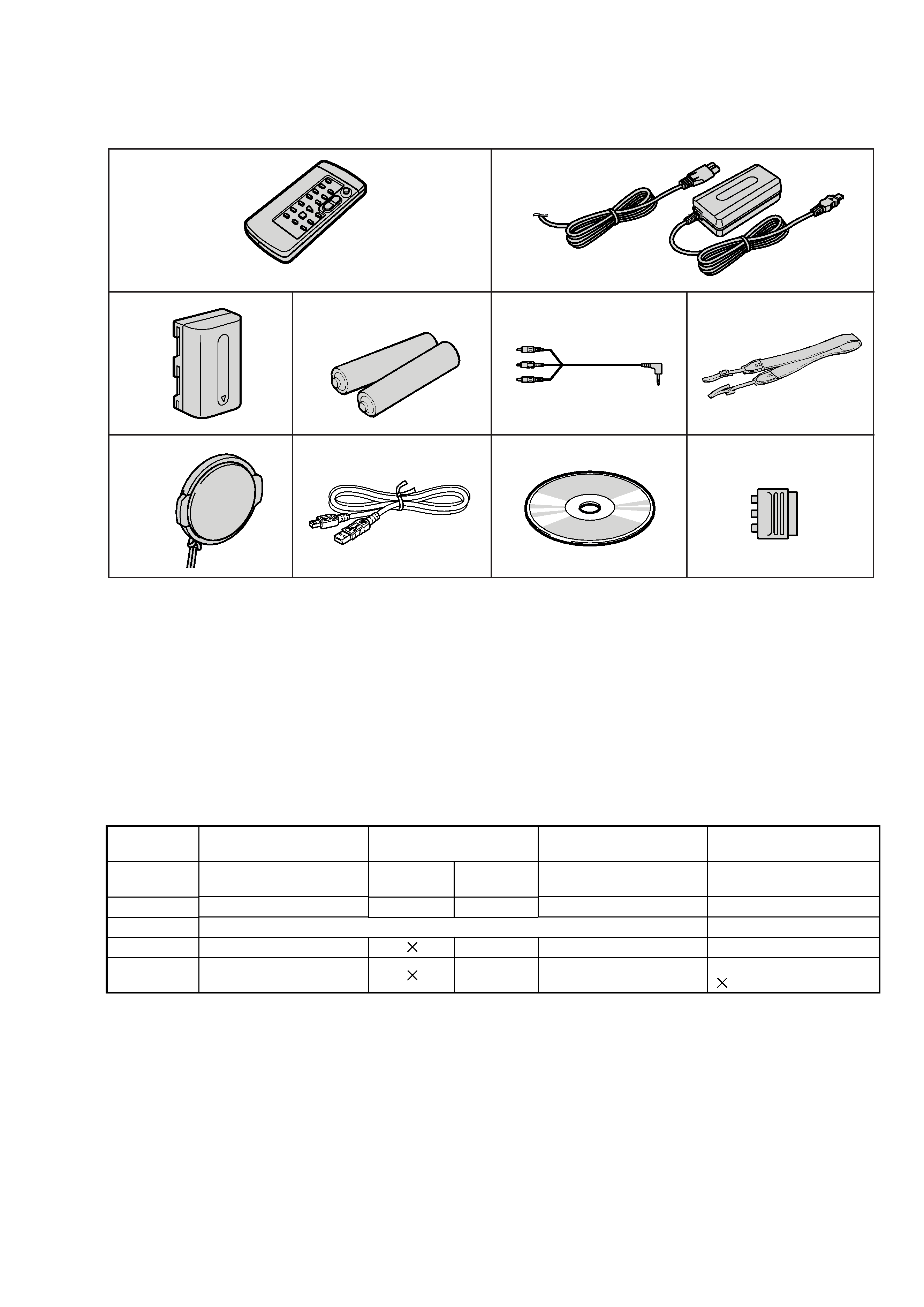
Supplied accessories
Table for differences of function
AEP, UK, EE,
NE, RU
PAL
Model
Destination
Color system
LCD type
VTR Rec
DV IN/OUT
DCR-TRV140
US, CND, E, HK, BR, JE
NTSC
a
a
E, HK, AUS,
CH, JE
PAL
a
a
DCR-TRV140E
Please refer to page 8 to discriminate the type of LCD (TYPE C or TYPE S).
DCR-TRV140M
US
NTSC
a
a
Remark
a : with REC button
a : with DV IN/OUT
: with DV OUT
1
2
3
45
6
78
RMT-814
9
q;
DCR-TRV140E: AEP, UK, EE, NE, RU
1
Wireless Remote Commander (1)
2
AC-L10A/L10B/L10C AC power adaptor (1)
Power cord (1)
3
NP-FM30 battery pack (1)
4
R6 (Size AA) battery for Remote
Commander (2)
5
A/V connecting cable (1)
6
Shoulder strap (1)
7
Lens cap (1)
8
USB Cable (1)
9
CD-ROM (SPVD-008 USB Driver) (1)
q;
21-pin adaptor (1)

4
DCR-TRV140/TRV140E/TRV140M
TABLE OF CONTENTS
Section
Title
Page
Section
Title
Page
SERVICE NOTE ................................................................... 6
1.
Power Supply During Repairs ....................................... 6
2.
To Take Out a Cassette When Not Eject
(Force Eject) .................................................................. 6
3.
Note for Repair .............................................................. 7
4.
LCD Type Check ............................................................ 7
SELF-DIAGNOSIS FUNCTION ........................................ 8
1.
Self-diagnosis Function ................................................. 8
2.
Self-diagnosis Display ................................................... 8
3.
Service Mode Display ................................................... 8
3-1.
Display Method .............................................................. 8
3-2.
Switching of Backup No. ............................................... 8
3-3.
End of Display ............................................................... 8
4.
Self-diagnosis Code Table ............................................ 9
1.
GENERAL
Checking Supplied Accessories .............................................. 1-1
Quick Start Guide .................................................................... 1-1
Using This Manual ................................................................... 1-2
Step 1 Preparing the Power Supply ........................................ 1-2
Step 2 Setting the Data and Time ........................................... 1-4
Step 3 Inserting a Cassette ..................................................... 1-5
Recording a Picture ................................................................. 1-5
Checking the Recording END SEARCH .............................. 1-8
Playing Back a Tape ................................................................ 1-9
Viewing the Recording on TV .................................................. 1-10
Recording a Still Image on a Tape Tape Photo Recording .. 1-11
Using the Wide Mode .............................................................. 1-12
Using the Fader Function ........................................................ 1-12
Using Special Effects Picture Effect ..................................... 1-13
Using Special Effects Digital Effect ...................................... 1-14
Using the PROGRAM AE Function ......................................... 1-14
Adjusting the Exposure Manually ............................................ 1-15
Focusing Manually ................................................................... 1-15
Interval Recording ................................................................... 1-16
Frame by Frame Recording Cut Recording ......................... 1-17
Superimposing a Title .............................................................. 1-17
Making Your Own Titles ........................................................... 1-18
Using the Built-in Light ............................................................ 1-18
Playing Back a Tape with Picture Effects ................................ 1-19
Playing Back a Tape with Digital Effects ................................. 1-20
Enlarging Images Recorded on Tapes Tape PB ZOOM ...... 1-20
Quickly Locating a Scene Using the Zero Set
Memory Function ..................................................................... 1-21
Searching a Recording by Date Date Search ...................... 1-21
Searching for a Photo Photo Search/Photo Scan ............... 1-22
Dubbing a Tape ........................................................................ 1-22
Dubbing a Tape Easily Easy Dubbing .................................. 1-23
Dubbing Only Desired Scenes Digital Program Editing ...... 1-26
Viewing Images Using Your Computer
USB Streaming (Windows Users Only) .............................. 1-29
Changing the Menu Settings ................................................... 1-31
Types of Trouble and Their Solutions ...................................... 1-34
Self-diagnosis Display ............................................................. 1-35
Warning Indicators and Messages .......................................... 1-36
About Video Cassettes ............................................................ 1-36
Abut the "InfoLITHIUM" Battery Pack ..................................... 1-37
About i.Link .............................................................................. 1-38
Using Your Camcorder Abroad ................................................ 1-38
Maintenance Information and Precautions ............................. 1-38
Identifying the Parts and Controls ........................................... 1-41
2.
DISASSEMBLY
2-1.
LCD Assembly, PD-156 Board ...................................... 2-2
2-2.
VF Lens Assembly, VF-150 Board ................................ 2-3
2-3.
Video Light and Front Panel Assembly ......................... 2-4
2-4.
Cabinet (L) Assembly .................................................... 2-4
2-5.
Cassette Lid Assembly .................................................. 2-4
2-6.
Cabinet (R) Assembly ................................................... 2-6
2-7.
EVF Block ...................................................................... 2-6
2-8.
Battery Panel Block ....................................................... 2-6
2-9.
Lens Assembly .............................................................. 2-7
2-10. VC-273 Board ................................................................ 2-8
2-11. FP-398 Flexible Board .................................................. 2-8
2-12. Control Switch Block (FK-2000) .................................... 2-8
2-13. Circuit Boards Location ................................................. 2-10
2-14. Flexible Boards Location ............................................... 2-11
3.
BLOCK DIAGRAMS
3-1.
Overall Block Diagram (1/5) .......................................... 3-1
3-2.
Overall Block Diagram (2/5) .......................................... 3-3
3-3.
Overall Block Diagram (3/5) .......................................... 3-5
3-4.
Overall Block Diagram (4/5) .......................................... 3-7
3-5.
Overall Block Diagram (5/5) .......................................... 3-9
3-6.
Power Block Diagram (1/2) ........................................... 3-11
3-7.
Power Block Diagram (2/2) ........................................... 3-13
4.
PRINTED WIRING BOARDS AND
SCHEMATIC DIAGRAMS
4-1.
Frame Schematic Diagrams .......................................... 4-3
Frame (1/2) Schematic Diagram ................................... 4-3
Frame (2/2) Schematic Diagram ................................... 4-5
4-2.
Printed Wiring Boards and Schematic Diagram ........... 4-7
CD-353 Printed Wiring Board and
Schematic Diagram ....................................................... 4-7
LS-057, FP-228, FP-299, FP-300, FP-302, FP-301
Flexible Printed Wiring Boards and
Schematic Diagram ....................................................... 4-9
VC-273 Printed Wiring Board ........................................ 4-11
VC-273 (CAMERA PROCESS)
Schematic Diagram ....................................................... 4-15
VC-273 (CAMERA Y/C PROCESS)
Schematic Diagram ....................................................... 4-17
VC-273 (LENS MOTOR DRIVE)
Schematic Diagram ....................................................... 4-19
VC-273 (DV SIGNAL PROCESS)
Schematic Diagram ....................................................... 4-21
VC-273 (DV INTERFACE) Schematic Diagram ............ 4-23
VC-273 (DIGITAL REC/PB AMP)
Schematic Diagram ....................................................... 4-25
VC-273 (VIDEO OUT) Schematic Diagram .................. 4-27
VC-273 (HI CONTROL) Schematic Diagram ............... 4-29
VC-273 (CAMERA/MECHA CONTROL)
Schematic Diagram ....................................................... 4-31
VC-273 (MECHANISM CONTROL)
Schematic Diagram ....................................................... 4-33
VC-273 (DRUM/CAPSTAN MOTOR DRIVE)
Schematic Diagram ....................................................... 4-35
VC-273 (AUDIO PROCESS) Schematic Diagram ........ 4-37
VC-273 (USB I/F), FP-399 Schematic Diagram ........... 4-39
FK2000, SS-2000,VC-273 (CONNECTOR), FP-398
Schematic Diagram ....................................................... 4-41
FP-398 Flexible Printed Wiring Board .......................... 4-43
VC-273 (DC IN, CHARGE) Schematic Diagram .......... 4-44
VC-273 (DC/DC CONVERTER)
Schematic Diagram ....................................................... 4-45
SI-033 Printed Wiring Board ......................................... 4-47
SI-033 Schematic Diagram ........................................... 4-49
PD-156 Printed Wiring Board ........................................ 4-51
PR-10000, PD-156 (RGB DRIVER,
TIMING GENERATOR) Schematic Diagram ................ 4-55
PD-156 (LCD DRIVER, BACK LIGHT DRIVE)
Schematic Diagram ....................................................... 4-57
LB-073 Printed Wiring Board and
Schematic Diagram ....................................................... 4-59

5
DCR-TRV140/TRV140E/TRV140M
Section
Title
Page
Section
Title
Page
VF-150 Printed Wiring Board ........................................ 4-60
VF-150 Schematic Diagram .......................................... 4-61
CF-2000 Schematic Diagram ........................................ 4-63
4-3.
Waveforms ..................................................................... 4-65
4-4.
Parts Location ............................................................... 4-68
5.
ADJUSTMENTS
1.
Before Starting Adjustment ........................................... 5-1
1-1.
Adjusting Items
when Replacing Main Parts and Boards ................. 5-2
5-1.
Camera Section Adjustment ......................................... 5-4
1-1.
Preparations Before Adjustment
(Camera Section) ..................................................... 5-4
1-1-1. List of Service Tools ................................................. 5-4
1-1-2. Preparations ............................................................. 5-5
1-1-3. Precaution ................................................................ 5-7
1.
Setting the Switch .................................................... 5-7
2.
Order of Adjustments ............................................... 5-7
3.
Subjects .................................................................... 5-7
1-2.
Initialization of 7, 8, C, D, E, F Page Data ............... 5-8
1-2-1. Initialization of 8, C, D Page Data ............................ 5-8
1.
Initializing the 8, C, D Page Data ............................. 5-8
2.
Modification of 8, C, D Page Data ........................... 5-8
3.
8 Page Table ............................................................. 5-8
4.
C Page Table ............................................................ 5-9
5.
D Page Table ............................................................ 5-10
1-2-2. Initialization of 7, E, F Page Data ............................ 5-11
1.
Initializing the 7, E, F Page Data ............................. 5-11
2.
Modification of 7, E, F Page Data ............................ 5-11
3.
7 Page Table ............................................................. 5-11
4.
E Page Table ............................................................ 5-12
5.
F Page Table ............................................................. 5-13
1-3.
Camera System Adjustments .................................. 5-14
1.
HALL Adjustment ..................................................... 5-14
2.
Flange Back Adjustment
(Using the Minipattern Box) ..................................... 5-15
3.
Flange Back Adjustment
(Using the Flange Back Adjustment Chart and
Subject More Than 500 m Away) ............................. 5-16
3-1.
Flange Back Adjustment (1) ..................................... 5-16
3-2.
Flange Back Adjustment (2) ..................................... 5-16
4.
Flange Back Check .................................................. 5-17
5.
Picture Frame Setting .............................................. 5-18
6.
Color Reproduction Adjustment ............................... 5-19
7.
AWB & LV Standard Data Input ............................... 5-20
8.
Auto White Balance Adjustment .............................. 5-21
9.
Auto White Balance Check ...................................... 5-22
10.
Angular Velocity Sensor Output Check and
Steady Shot Check .................................................. 5-23
1-4.
Electronic Viewfinder System Adjustments ............. 5-24
1.
RGB AMP Adjustment (VF-150 Board) ................... 5-25
2.
Contrast Adjustment (VF-150 Board) ...................... 5-25
1-5.
LCD System Adjustments ........................................ 5-26
1.
VCO Adjustment (PD-156 Board) ............................ 5-26
2.
RGB AMP Adjustment (PD-156 Board) ................... 5-27
3.
Contrast Adjustment (PD-156 Board) ...................... 5-27
4.
COM AMP Adjustment (PD-156 Board) .................. 5-28
5.
V-COM Adjustment (PD-156 Board) ........................ 5-28
6.
White Balance Adjustment (PD-156 Board) ............ 5-29
5-2.
Mechanism Section Adjustment ................................... 5-30
2-1.
Adjustment Remote Commander ............................ 5-30
2-2.
How to Enter Record Mode Without Cassette ......... 5-30
2-3.
How to Enter Playback Mode Without Cassette ...... 5-30
2-4.
Tape Path Adjustment .............................................. 5-31
2-4-1. Preparations for Adjustment .................................... 5-31
2-4-2. Tape Path Adjustment .............................................. 5-32
2-4-3. No.7 Guide (TG7) Adjustment ................................. 5-33
2-4-4. CUE, REV Waveforms Check .................................. 5-33
2-5.
Checks After Adjustments ........................................ 5-33
2-5-1. Waveform Build-up Check ........................................ 5-33
2-5-2. Tape Path Check ...................................................... 5-33
5-3.
Video Section Adjustment ............................................. 5-34
3-1.
Preparations Before Adjustments ............................ 5-34
3-1-1. Equipment to Required ............................................ 5-34
3-1-2. Precautions on Adjusting ......................................... 5-35
3-1-3. Adjusting Connectors ............................................... 5-36
3-1-4. Connecting the Equipment ....................................... 5-36
3-1-5. Alignment Tape ......................................................... 5-37
3-1-6. Input/output Level and Impedance .......................... 5-37
3-2.
System Control System Adjustment ........................ 5-38
1.
Initialization of 7, 8, C, D, E, F Page Data ............... 5-38
2.
Node Unique ID No. Input ........................................ 5-38
2-1.
Input of Company ID ................................................ 5-38
2-2.
Input of Serial No. ..................................................... 5-38
3-3.
Servo and RF System Adjustments ......................... 5-40
1.
REEL FG Adjustment (VC-273 Board) .................... 5-40
2.
CAP FG Duty Adjustment (VC-273 Board) ............. 5-40
3.
PLL f0 & LPF f0 Pre-adjustment (VC-273 Board) ..... 5-41
4.
Switching Position Adjustment (VC-273 Board) ...... 5-42
5.
AGC Center Level Adjustment (VC-273 Board) ...... 5-43
6.
APC & AEQ Adjustment (VC-273 Board) ................ 5-44
7.
PLL f0 & LPF f0 Final Adjustment
(VC-273 Board) ........................................................ 5-45
3-4.
Video System Adjustments ...................................... 5-46
1.
27 MHz Origin Oscillation Adjustment
(VC-273 Board) ........................................................ 5-46
2.
S VIDEO OUT Y Level Adjustment
(VC-273 Board) ........................................................ 5-46
3.
S VIDEO OUT Chroma Level Adjustment
(VC-273 Board) ........................................................ 5-47
4.
VIDEO OUT Y, Chroma Level Check
(VC-273 Board) ........................................................ 5-48
3-5.
Audio System Adjustments ...................................... 5-49
1.
Digital8 Playback Level Check ................................. 5-49
5-4.
Service Mode ................................................................ 5-50
4-1.
Adjustment Remote Commander ............................ 5-50
1.
Using the Adjustment Remote Commander ............ 5-50
2.
Precautions Upon Using the Adjustment
Remote Commander ................................................ 5-50
4-2.
Data Process ............................................................ 5-51
4-3.
Service Mode ........................................................... 5-52
1.
Setting the Test Mode .............................................. 5-52
2.
Emergence Memory Address .................................. 5-52
2-1.
C Page Emergence Memory Address ..................... 5-52
2-2.
EMG Code (Emergency Code) ................................ 5-53
2-3.
MSW Code ............................................................... 5-54
3.
Bit Value Discrimination ........................................... 5-55
4.
Switch Check (1) ...................................................... 5-55
5.
Switch Check (2) ...................................................... 5-55
6.
Switch Check (3) ...................................................... 5-56
7.
LED, LCD (Display Window) Check ......................... 5-56
8.
Record of Use Check ............................................... 5-57
9.
Record of Self-diagnosis Check .............................. 5-58
6.
REPAIR PARTS LIST
6-1.
Exploded Views ............................................................. 6-1
6-1-1. Front Panel Block ..................................................... 6-1
6-1-2. Cabinet (R) Block ..................................................... 6-2
6-1-3. LCD Block ................................................................. 6-3
6-1-4. EVF Block ................................................................. 6-4
6-1-5. Cabinet (L) and Battery Panel Blocks ...................... 6-5
6-1-6. Lens Block ................................................................ 6-6
6-1-7. Main Board Block ..................................................... 6-7
6-1-8. Cassette Compartment Assembly,
Drum Assembly ........................................................ 6-8
6-1-9.
LS Chassis Block Assembly .................................... 6-9
6-1-10. Mechanical Chassis Block Assembly-1 ................... 6-10
6-1-11. Mechanical Chassis Block Assembly-2 ................... 6-11
6-2.
Electrical Parts List ....................................................... 6-12
* The color reproduction frame is shown on page 235.