DCR-TRV103/TRV110/TRV110E/TRV110P/TRV203/TRV210/
TRV210E/TRV310/TRV310E/TRV310P/TRV315
DCR-TR7000/TR7000E/TR7100E
RMT-814
US Model
DCR-TRV103/TRV110/TRV210/TRV310/TRV315/TR7000
Canadian Model
DCR-TRV103/TRV110/TRV203/TRV210/TRV315/TR7000
E Model
DCR-TRV110/TRV110E/TRV110P/
TRV310/TRV310E/TRV310P
Hong Kong Model
DCR-TRV110/TRV110E/TRV310/TRV310E
AEP Model
DCR-TRV110E/TRV210E/TRV310E/
TR7000E/TR7100E
UK Model
DCR-TRV110E/TRV210E/TRV310E/TR7000E
Tourist Model
DCR-TRV110E/TRV310/TRV310E
Australian Model
DCR-TRV110E/TRV310E
Brazilian Model
DCR-TRV110
Chinese Model
DCR-TRV110E/TRV210E/TRV310E
East European Model
North European Model
Russian Model
DCR-TRV110E
Taiwan Model
DCR-TRV310
SERVICE MANUAL
DIGITAL VIDEO CAMERA RECORDER
MICROFILM
Photo: DCR-TRV310E
SPECIFICATIONS
NTSC MODEL : DCR-TRV103/TRV110/TRV110P/TRV203/TRV210/
TRV310/TRV310P/TRV315/TR7000
PAL MODEL
: DCR-TRV110E/TRV210E/TRV310E/TR7000E/TR7100E
B800 MECHANISM
For MECHANISM ADJUSTMENT, refer to
the "8mm Video MECHANICAL
ADJUSTMENT MANUAL
" (9-973-801-11).
Video camera
recorder
System
Video recording system
2 rotary heads
Helical scanning system
Audio recording system
Rotary heads, PCM system
Quantization: 12 bits (Fs 32 kHz,
stereo 1, stereo 2), 16 bits
(Fs 48 kHz, stereo)
Video signal
NTSC color, EIA standards
DCR-TRV103/TRV110/TRV110P/
TRV203/TRV210/TRV310/
TRV310P/TRV315/TR7000:
PAL color , CCIR standards
TRV110E/TRV210E/TRV310E/
TR7000E/TR7100E:
Recommended cassette
Hi8 video cassette
Recording/playback time
DCR-TRV103/TRV110/TRV110P/
TRV203/TRV210/TRV310/TRV310P/
TRV315/TR7000: (using 120 min.
cassette)
1 hours
DCR-TRV110E/TRV210E/TRV310E/
TR7000E/TR7100E: (using 90 min.
cassette)
1 hours
Fastforward/rewind time DCR-
TRV103/TRV110/TRV110P/TRV203/
TRV210/TRV310/TRV310P/TRV315/
TR7000: (using 120 min. cassette)
DCR-TRV110E/TRV210E/TRV310E/
TR7000E/TR7100E: (using 90 min.
cassette)
Approx. 8 min.
Image device
1/4 inch CCD (Charge Coupled
Device)
DCR-TRV103/TRV110/TRV110P/
TRV203/TRV210/TRV310/
TRV310P/TRV315/TR7000:
Approx. 460,000 pixels
(Effective: Approx. 290,000 pixels)
DCR-TRV110E/TRV210E/
TRV310E/TR7000E/TR7100E:
Approx. 800,000 pixels
(Effective: Approx. 400,000 pixels)
Viewfinder
Electronic viewfinder
DCR-TRV315/TR7000/TR7000E/
TR7100E:
Monochrome
DCR-TRV103/TRV110/TRV110E/
TRV110P/TRV203/TRV210/
TRV210E/TRV310/TRV310E/
TRV310P:
Color
Lens
Combined power zoom lens
Filter diameter 1 7/16 in. (37 mm)
20
× (Optical),
DCR-TRV103/TRV110/TRV110E:
EE, NE, RU/TRV110P/TRV203/
TRV210/TRV210E: CN/TRV310/
TRV310E/TRV310P: E, HK,
AUS, CN, JE/TRV315/TR7000:
360
× (Digital)
DCR-TRV110E: AEP, UK/TRV210E:
AEP, UK/TRV310E: AEP, UK/
TR7000E/TR7100E:
80
× (Digital)
Focal length
5/32 - 2 7/8 in. (3.6 - 72 mm)
When converted to a 35 mm still
camera
1 5/8 - 32 3/8 in. (41 - 820 mm)
Color temperature
Auto
Minimum illumination
DCR-TRV103/TRV110/TRV110P/
TRV203/TRV210/TRV310/
TRV310P/TRV315/TR7000:
1.0 lux (F 1.4)
DCR-TRV110E/TRV210E/
TRV310E/TR7000E/TR7100E:
3 lux (F 1.4)
0 lux (in the NightShot mode)*
* Objects unable to be seen due to
the dark can be shot with
infrared lighting
Input and output
connectors
DCR-TRV103/TRV110/TRV110E: E,
HK, AUS, CN, JE/TRV110P/TRV203/
TRV210/TRV210E: CN/TRV310/
TRV310E: E, HK, AUS, CN, JE/
TRV310P/TRV315/TR7000:
S video input/output
DCR-TRV110E: AEP, UK, EE, NE,
RU/TRV210E: AEP, UK/TRV310E:
AEP, UK/TR7000E/TR7100E:
S video output
4-pin mini DIN
Luminance signal: 1 Vp-p,
75 ohms, unbalanced
DCR-TRV103/TRV110/TRV110P/
TRV203/TRV210/TRV310/
TRV310P/TRV315/TR7000:
Chrominance signal: 0.286 Vp-p,
DCR-TRV110E/TRV210E/
TRV310E/TR7000E/TR7100E:
Chrominance signal: 0.3 Vp-p
75 ohms, unbalanced
DCR-TRV103/TRV110/TRV110E: E,
HK, AUS, CN, JE/TRV110P/TRV203/
TRV210/TRV210E: CN/TRV310/
TRV310E: E, HK, AUS, CN, JE/
TRV310P/TRV315/TR7000:
Video input/output
DCR-TRV110E: AEP, UK, EE, NE,
RU/TRV210E: AEP, UK/TRV310E:
AEP, UK/TR7000E/TR7100E:
Video output
Phono jack, 1 Vp-p, 75 ohms,
unbalanced
DCR-TRV103/TRV110/TRV110E: E,
HK, AUS, CN, JE/TRV110P/TRV203/
TRV210/TRV210E: CN/TRV310/
TRV310E: E, HK, AUS, CN, JE/
TRV310P/TRV315/TR7000:
Audio input/output
DCR-TRV110E: AEP, UK, EE, NE,
RU/TRV210E: AEP, UK/TRV310E:
AEP, UK/TR7000E/TR7100E:
Audio output
Phono jacks (2: stereo L and R)
327 mV, (at output impedance
47 kilohms) impedance less than
2.2 kilohms
RFU DC OUT
Special minijack, DC 5V
Ver 1.3 2001. 01

-- 2 --
DCR-TRV103/TRV110/TRV110E: E,
HK, AUS, CN, JE/TRV110P/TRV203/
TRV210/TRV210E: CN/TRV310/
TRV310E: E, HK, AUS, CN, JE/
TRV310P/TRV315/TR7000:
DV input/output
DCR-TRV110E: AEP, UK, EE, NE,
RU/TRV210E: AEP, UK/TRV310E:
AEP, UK/TR7000E/TR7100E:
DV output
4-pin connector
Headphone jack
Stereo minijack (ø 3.5 mm)
LANC control jack
Stereo mini-minijack (ø 2.5 mm)
MIC jack
Minijack, 0.388 mV low impedance
with 2.5 to 3.0 V DC, output
impedance 6.8 kilohms (ø 3.5 mm)
Stereo type
LCD screen
Picture
DCR-TRV103/TRV110/TRV110E/
TRV110P:
2.5 inches measured diagonally
2
× 1 1/2 in. (50.3 × 37.4 mm)
DCR-TRV203/TRV210/TRV210E/
TRV315:
3 inches measured diagonally
2 3/8
× 1 3/4 in. (59.5 × 43.2 mm)
DCR-TRV310/TRV310E/TRV310P:
3.5 inches measured diagonally
2 7/8
× 2 in. (72.4 × 50.4 mm)
Total dot number
DCR-TRV103/TRV110/TRV110E/
TRV110P:
61,380 (279
× 220)
DCR-TRV203/TRV210/TRV210E/
TRV315:
89,622 (383
× 234)
DCR-TRV310/TRV310E/TRV310P:
105,380 (479
× 220)
General
Power requirements
7.2 V (battery pack)
8.4 V (AC power adaptor)
Average power consumption
(when using the battery pack)
During camera recording using
LCD
DCR-TRV103/TRV110/TRV110P:
3.5 W
DCR-TRV110E: 3.6 W
DCR-TRV203/TRV210/TRV210E/
TRV315: 3.9 W
DCR-TRV310/TRV310E/TRV310P:
4.2 W
Viewfinder
DCR-TRV110E/TRV203/TRV210/
TRV210E/TRV310/TRV310E/
TRV310P: 3.2 W
DCR-TRV103/TRV110/TRV110P/
TRV315: 3.1 W
During camera recording
DCR-TR7000/TR7000E/TR7100E:
3.1 W
Operating temperature
32
°F to 104 °F (0 °C to 40 °C)
Storage temperature
4
°F to +140 °F (20 °C to +60 °C)
Dimensions (Approx.)
DCR-TRV103/TRV110/TRV110E/
TRV110P:
4
× 4 1/4 × 8 5/8 in.
(101
× 107 × 217 mm) (w/h/d)
DCR-TRV203/TRV210/TRV210E/
TRV310/TRV310E:
4 3/8
× 4 1/4 × 8 5/8 in.
(108
× 107 × 217 mm) (w/h/d)
DCR-TRV315:
4 3/8
× 4 1/4 × 7 3/4 in.
(108
× 106 × 195 mm) (w/h/d)
DCR-TR7000/TR7000E/TR7100E:
4
× 4 1/4 × 7 3/4 in.
(101
× 106 × 195 mm) (w/h/d)
Mass (approx.)
DCR-TRV103/TRV110/TRV110E/
TRV110P:
1 lb 15 oz (890 g)
DCR-TRV203/TRV210/TRV210E/
TRV315:
2 lb (930 g)
DCR-TRV310/TRV310E:
2 lb 1 oz (960 g)
DCR-TR7000/TR7000E/TR7100E:
1 lb 11 oz (790 g)
excluding the battery pack, lithium
battery, cassette and shoulder
strap
DCR-TRV203/TRV210/TRV210E/
TRV310/TRV310E/TRV310P/
TRV315:
2 lb 6 oz (1.1 kg)
DCR-TRV103/TRV110/TRV110E/
TRV110P:
2 lb 3 oz (1 kg)
DCR-TR7000/TR7000E/TR7100E:
1 lb 11 oz (790 g)
including the battery pack
NP-F330, lithium battery CR2025,
120 min. cassette
(DCR-TRV103/TRV110/TRV110P/
TRV203/TRV210/TRV310/
TRV310P/TRV315/TR7000), 90 min.
cassette (DCR-TRV110E/TRV210E/
TRV310E/TR7000E/TR7100E)
and shoulder strap
Supplied accessories
See page 3.
AC power adaptor
Power requirements
100 - 240 V AC, 50/60 Hz
Power consumption
23 W
Output voltage
DC OUT: 8.4 V, 1.5 A in operating
mode
Operating temperature
32
°F to 104 °F (0 °C to 40 °C)
Storage temperature
4
°F to +140 °F (20 °C to +60 °C)
Dimensions (approx.)
5
× 1 9/16 × 2 1/2 in.
(125
× 39 × 62 mm) (w/h/d)
excluding projecting parts
Mass (approx.)
9.8 oz (280 g)
excluding power cord
Cord length (approx.)
AC power cord: 6.6 feet (2 m)
Connecting cord: 5.2 feet (1.6 m)
Design and specifications are
subject to change without notice.
· Abbreviation
EE
: East European model
NE : North European model
RU : Russian model
HK : Hong Kong model
AUS : Australian model
CN : Chinese model
JE
: Tourist model
-- 3 --
SAFETY-RELATED COMPONENT WARNING!!
COMPONENTS IDENTIFIED BY MARK
! OR DOTTED LINE WITH
MARK
! ON THE SCHEMATIC DIAGRAMS AND IN THE PARTS
LIST ARE CRITICAL TO SAFE OPERATION. REPLACE THESE
COMPONENTS WITH SONY PARTS WHOSE PART NUMBERS
APPEAR AS SHOWN IN THIS MANUAL OR IN SUPPLEMENTS
PUBLISHED BY SONY.
ATTENTION AU COMPOSANT AYANT RAPPORT
À LA SÉCURITÉ!
LES COMPOSANTS IDENTIFÉS PAR UNE MARQUE
! SUR LES
DIAGRAMMES SCHÉMATIQUES ET LA LISTE DES PIÈCES SONT
CRITIQUES POUR LA SÉCURITÉ DE FONCTIONNEMENT. NE
REMPLACER CES COMPOSANTS QUE PAR DES PIÈSES SONY
DONT LES NUMÉROS SONT DONNÉS DANS CE MANUEL OU
DANS LES SUPPÉMENTS PUBLIÉS PAR SONY.
1.
Check the area of your repair for unsoldered or poorly-soldered
connections. Check the entire board surface for solder splashes
and bridges.
2.
Check the interboard wiring to ensure that no wires are
"pinched" or contact high-wattage resistors.
3.
Look for unauthorized replacement parts, particularly
transistors, that were installed during a previous repair. Point
them out to the customer and recommend their replacement.
4.
Look for parts which, through functioning, show obvious signs
of deterioration. Point them out to the customer and
recommend their replacement.
5.
Check the B+ voltage to see it is at the values specified.
6.
Flexible Circuit Board Repairing
· Keep the temperature of the soldering iron around 270°C
during repairing.
· Do not touch the soldering iron on the same conductor of the
circuit board (within 3 times).
· Be careful not to apply force on the conductor when soldering
or unsoldering.
SAFETY CHECK-OUT
After correcting the original service problem, perform the following
safety checks before releasing the set to the customer.
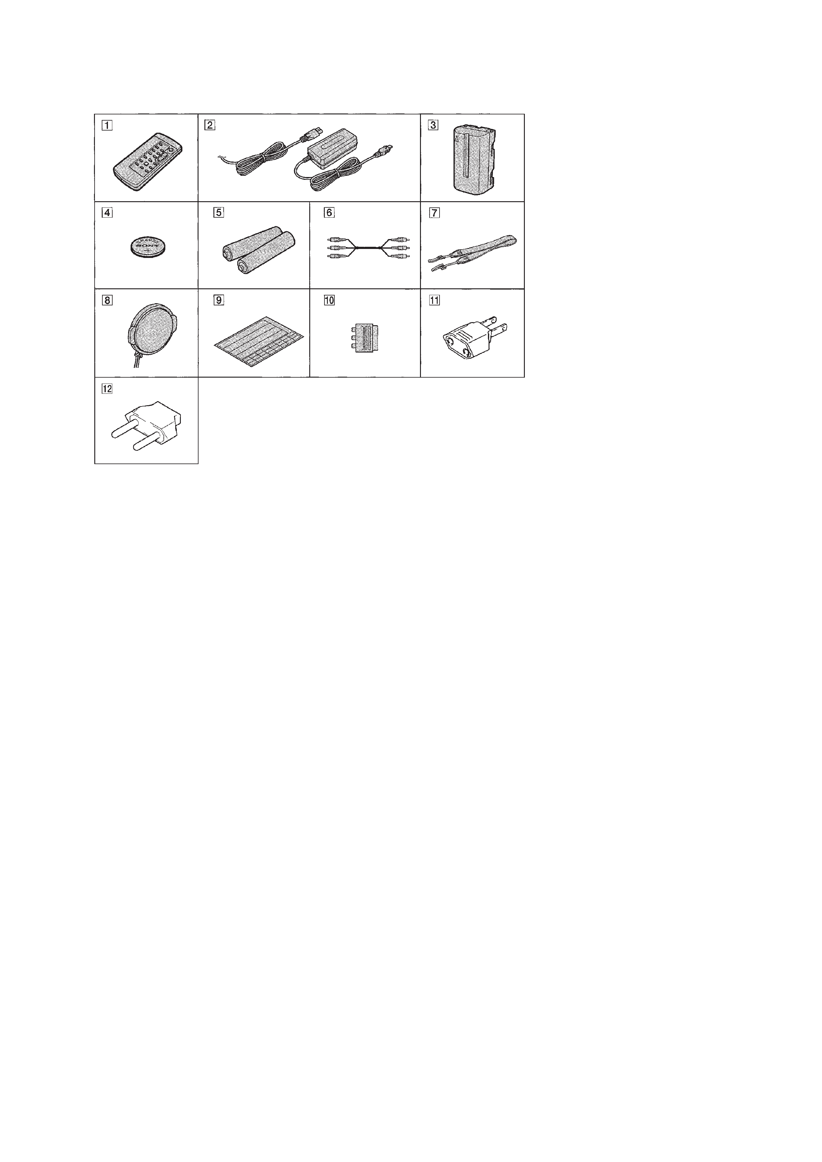
Supplied accessories
1 Wireless Remote Commander (1)
2 AC-L10A/L10B/L10C AC power
adaptor (1), Power cord (1)
3 NP-F330 Battery pack (1)
4 CR2025 Lithium Battery (1)
The lithium battery is already installed in your
camcorder.
5 Size AA (R6) battery for Remote
Commander (2)
6 A/V connecting cable (1)
!TM 2-pin conversion adaptor (1)
DCR-TRV110E: JE/TRV310E: JE/
TRV310: JE only
· Abbreviation
EE
: East European model
NE : North European model
RU : Russian model
HK : Hong Kong model
BR : Brazilian model
JE
: Tourist model
7 Shoulder strap (1)
8 Lens cap (1)
9 Label sheet for cassette (1)
Stick this label on the recorded cassette.
0 21-pin adaptor (1)
DCR-TR7000E/TR7100E/TRV210E:AEP, UK/
TRV310E: AEP, UK/TRV110E: AEP, UK,
EE, NE, RU only
!¡ 2-pin conversion adaptor (1)
DCR-TRV110E: E, HK/TRV110: E, HK, BR/
TRV110P/TRV310E: E, HK/TRV310: E, HK/
TRV310P only

-- 4 --
Note
:
EE,
NE,
R
U
model
is
360
×.
Remark
NTSC
:
X251
is
28.6363MHz
P
AL
:
X251
is
28.375MHz
960H:with
IC503
of
VC-213
boar
d
®
:with
Q641-644
of
VC-213
board
®
:with
REC
b
utton
and
Q641-
644
of
VC-213
board
2.5
inch
:
with
PD-105
board
3/3.5
inch
:
with
PD-106
board
Color
:
with
VF-126
boar
d
B/W
:
with
VF-129
boar
d
CN
PA
L
RMT
-814
20
×
360
×
960H
®
®
3.0
89k
TYPE
S
B/W
CD-213
CF-63
MA-355
PD-106
VF-129
SE-87
PJ-96
DCR-
TR
V310/
TR
V310P
US,
E,
HK,
JE,
TW
NTSC
RMT
-814
20
×
360
×
720H
®
®
3.5
105k
TYPE
C
B/W
CD-212
CF-63
MA-355
PD-106
VF-129
SE-87
PJ-96
DCR-
TR
V310E
AEP
,UK
PA
L
RMT
-814
20
×
80
×
960H
®
!
3.5
105k
TYPE
S
B/W
CD-213
CF-63
MA-355
PD-106
VF-129
SE-87
PJ-96
E,
HK,
A
U
S,
CN,
JE
PA
L
RMT
-814
20
×
360
×
960H
®
®
3.5
105k
TYPE
S
B/W
CD-213
CF-63
MA-355
PD-106
VF-129
SE-87
PJ-96
DCR-
TR
V315
US,
CND
NTSC
RMT
-814
20
×
360
×
720H
®
®
3.0
89k
TYPE
S
Color
CD-212
CF-63
MA-355
PD-106
VF-126
SE-87
PJ-96
DCR-
TR7000
US,
CND
NTSC
RMT
-814
20
×
360
×
720H
!
®
!
!
!
Color
CD-212
CF-65
MA-357
!
VF-126
SE-89
PJ-98
DCR-
TR7000E/
TR7100E
AEP
,UK
PA
L
RMT
-814
20
×
80
×
960H
!
!
!
!
!
Color
CD-213
CF-65
MA-357
!
VF-126
SE-89
PJ-98
Model
Destination
Color
system
Remote
Commander
Lens
Digital
zoom
CCD
imager
MONIT
OR
IN
VTR
REC
LCD
(size)
LCD
(pix
el)
LCD
type
V
ie
w
f
inder
CD
board
CF
board
MA
board
PD
board
VF
board
SE
board
PJ
board
DCR-
TR
V110/
TR
V110P/
TR
V103
US,
CND,
E,
HK,
BR
NTSC
RMT
-814
20
×
360
×
720H
®
®
2.5
61k
TYPE
S
B/W
CD-212
CF-62
MA-354
PD-105
VF-129
SE-86
PJ-95
DCR-
TR
V110E
AEP
,UK,
EE,
NE,
R
U
PA
L
RMT
-814
20
×
80
×(Note)
960H
®
!
2.5
84k
TYPE
S
B/W
CD-213
CF-62
MA-354
PD-105
VF-129
SE-86
PJ-95
E,
HK,
A
U
S,
CN,
JE
PA
L
RMT
-814
20
×
360
×
960H
®
®
2.5
61k
TYPE
S
B/W
CD-213
CF-62
MA-354
PD-105
VF-129
SE-86
PJ-95
DCR-
TR
V203
CND
NTSC
RMT
-814
20
×
360
×
720H
®
®
3.0
89k
TYPE
S
B/W
CD-212
CF-63
MA-355
PD-106
VF-129
SE-87
PJ-96
DCR-
TR
V210
US,
CND
NTSC
RMT
-814
20
×
360
×
720H
®
®
3.0
89k
TYPE
S
B/W
CD-212
CF-63
MA-355
PD-106
VF-129
SE-87
PJ-96
DCR-
TR
V210E
AEP
,UK
PA
L
RMT
-814
20
×
80
×
960H
®
!
3.0
89k
TYPE
S
B/W
CD-213
CF-63
MA-355
PD-106
VF-129
SE-87
PJ-96
T
a
b
le
f
or
diff
erence
of
function
·
A
b
b
re
via
tion
CND
:Canadian
model
EE
:East
European
model
NE
:North
European
model
R
U
:Russian
model
HK
:Hong
K
ong
model
A
U
S
:Australian
model
CN
:Chinese
model
BR
:Brazilian
model
JE
:T
ourist
model
TW
:T
aiw
an
model

-- 5 --
SERVICE NOTE
1.
POWER SUPPLY DURING REPAIRS ····························· 8
2.
TO TAKE OUT A CASSETTE WHEN NOT EJECT
(FORCE EJECT) ································································ 8
SELF-DIAGNOSIS FUNCTION
1.
Self-diagnosis Function ······················································ 9
2.
Self-diagnosis Display ························································ 9
3.
Service Mode Display ························································ 9
3-1.
Display Method ·································································· 9
3-2.
Switching of Backup No. ··················································· 9
3-3.
End of Display ···································································· 9
4.
Self-dignosis Code Table ·················································· 10
1.
GENERAL
Quick Start Guide ······································································ 1-1
Getting Started ··········································································· 1-1
Using this manual ·································································· 1-1
Checking supplied accessories ·············································· 1-1
Step 1: Preparing the power supply ······································· 1-2
Step 2: Inserting a cassette ···················································· 1-3
Recording Basics ···································································· 1-3
Recording a picture ································································ 1-3
Checking the recording
END SEARCH/EDITSEARCH/Rec Review ····················· 1-5
Playback Basics ······································································ 1-5
Playing back a tape ································································ 1-5
Viewing the recording on TV ················································ 1-6
Advanced Recording Operations ··············································· 1-6
Photo recording ······································································ 1-6
Using the wide mode ····························································· 1-7
Using the fader function ························································ 1-7
Using special effects Picture effect ····································· 1-8
Using special effects Digital effect ····································· 1-8
Using the PROGRAM AE function ······································· 1-9
Adjusting the exposure manually ·········································· 1-9
Focusing manually ······························································· 1-10
Inserting a scene ·································································· 1-10
Advanced Playback Operations ··············································· 1-10
Playing back a tape with picture effects ······························ 1-10
Playing back a tape with digital effects ······························· 1-10
Quickly locating a scene using the zero set memory
function ················································································ 1-11
Searching a recording by date ·············································· 1-11
Searching for a photo Photo search/Photo scan ················ 1-11
Editing on Other Equipment ···················································· 1-12
Dubbing a tape ····································································· 1-12
Recording video or TV programs ········································ 1-12
Inserting a scene from a VCR ·············································· 1-13
Customizing Your Camcorder ················································· 1-13
Changing the MENU settings ·············································· 1-13
Resetting the date and time ·················································· 1-14
Additional Information ···························································· 1-14
Digital8 system, recording and playback ····························· 1-15
Changing the lithium battery in your camcorder ················· 1-15
Troubleshooting ··································································· 1-16
Self-diagnosis display ·························································· 1-17
Warning indicators and messages ········································ 1-17
Using your camcorder abroad ·············································· 1-17
Maintenance information and precautions ··························· 1-17
Quick Reference ······································································ 1-18
Identifying the parts and controls ········································ 1-18
Quick Function Guide ························································· 1-20
2.
DISASSEMBLY
2-1.
2.5 INCH LCD Unit, PD-105 Board ······························· 2-2
2-2.
3.0/3.5 INCH LCD Unit, PD-106 Board ························· 2-3
2-3.
F Panel Assembly, Cabinet (R) Assembly ······················· 2-4
2-4.
MA-354, 355, 357 Board ················································ 2-4
2-5.
Mechanism Deck ····························································· 2-5
2-6.
EVF Block Assembly ······················································ 2-6
2-7.
VF-129 Board (B/W EVF Model) ··································· 2-7
2-8.
VF-126 Board (Color EVF Model) ································· 2-8
2-9.
Lens Block ······································································· 2-9
2-10. Mechanism Deck, VC-213, DD-117,
PJ-95, 96, 98 Boards ······················································ 2-10
2-11. CF-65 Board (TR Model) ·············································· 2-12
2-12. CF-62 Board (2.5 INCH LCD Model) ·························· 2-12
2-13. CF-63 Board (3.0/3.5 INCH LCD Model) ···················· 2-12
2-14. Circuit Boards Location ················································ 2-13
2-15. Flexible Boards Location ·············································· 2-14
3.
BLOCK DIAGRAMS
3-1.
Overall Block Diagram (1) ·············································· 3-1
Overall Block Diagram (2) ·············································· 3-6
3-2.
Power Block Diagram (1) ················································ 3-9
Power Block Diagram (2) ·············································· 3-13
4.
PRINTED WIRING BOARDS AND
SCHEMATIC DIAGRAMS
4-1.
Frame Schematic Diagram-1 ··········································· 4-1
Frame Schematic Diagram-2 ··········································· 4-5
4-2.
Printed Wiring Boards and Schematic Diagrams ············ 4-9
· CD-212 (CCD Imager)
Printed Wiring Board and
Schematic Diagram ······································· 4-10
· CD-213 (CCD Imager)
Printed Wiring Board and
Schematic Diagram ······································· 4-13
· VC-213 (Camera Processor)(1/13)
Schematic Diagram ....................................... 4-15
· VC-213 (Y/C Processor)(2/13)
Schematic Diagram ······································· 4-18
· VC-213 (Lens Motor Drive)(3/13)
Schematic Diagram ······································· 4-21
· VC-213 (I/O SEL, IR, BBI)(4/13)
Schematic Diagram ······································· 4-25
· VC-213 (VFD)(5/13)
Schematic Diagram ······································· 4-29
· VC-213 (SFD, TFD, LIP)(6/13)
Schematic Diagram ······································· 4-33
· VC-213 (TRX, TRF, TRW)(7/13)
Schematic Diagram ······································· 4-35
· VC-213 (8mm PB RF AMP, D/A Converter)(8/13)
Schematic Diagram ······································· 4-40
· VC-213 (8mm AFM Processor)(9/13)
Schematic Diagram ······································· 4-43
· VC-213 (8mm Mechanism Control)(10/13)
Schematic Diagram ······································· 4-49
· VC-213 (DV Mechanism Control)(11/13)
Schematic Diagram ······································· 4-51
· FP-249 (S/T Reel Sensor), FP-356 (Top Sensor),
FP-355 (Tape LED) Flexible Board ···························· 4-55
· VC-213 (Servo)(12/13)
Schematic Diagram ······································· 4-56
· VC-213 (HI Control)(13/13)
Schematic Diagram ······································· 4-59
· VC-213 (Camera Processor, Y/C Processor, Lens Motor
Drive, IN/OUT Select, IR Transmitter, Base Band Input,
VFD, SFD, TFD, LIP, TRX, TRF, TRW, 8mm PB RF
AMP, D/A Converter, 8mm AFM Processor, 8mm
Mechanism Control, DV Mechanism Control, Servo,
HI Control)
Printed Wiring Board ···································· 4-65
TABLE OF CONTENTS